2007-01 C:1
Table of contents
TABLE OF CONTENTS
Preface .....................................................1:1
Loader identification ................................................ 1:1
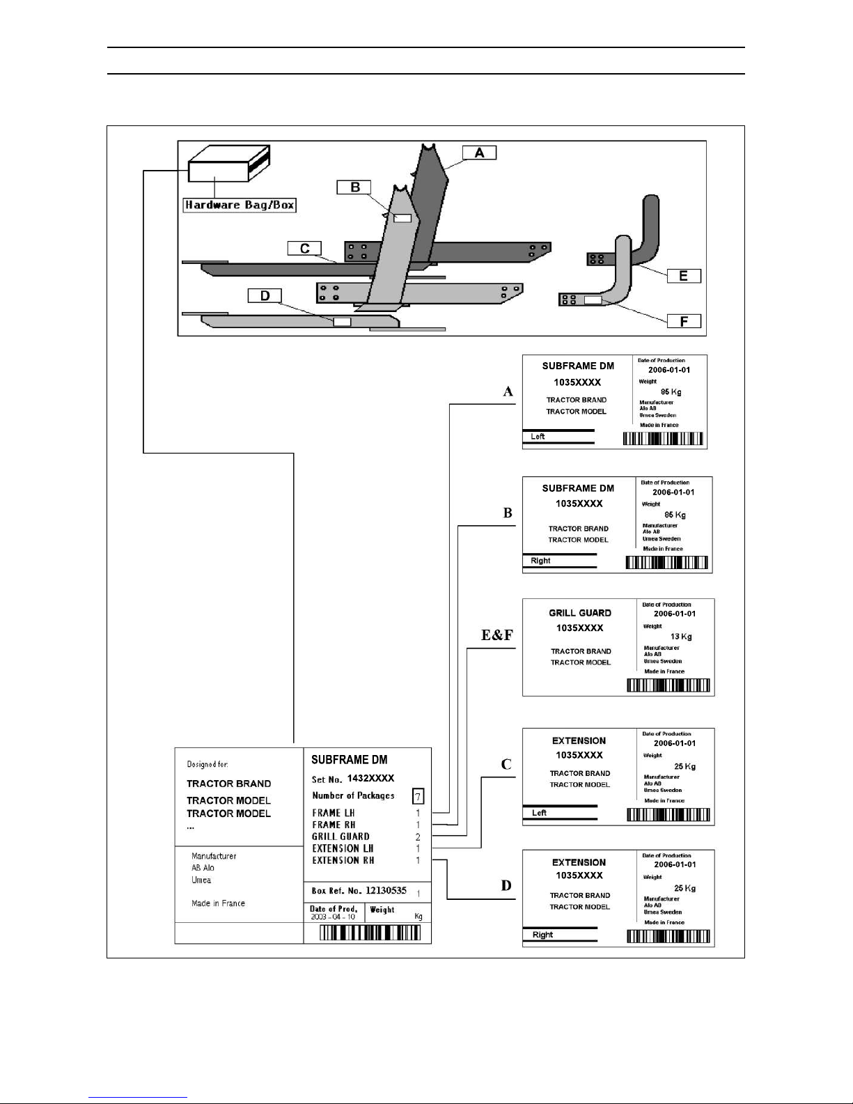
Subframe identification............................................ 1:2
Safety instructions ..................................2:1
General information................................................. 2:1
Explanation of warning levels.................................. 2:2
Symbol explanation ................................................. 2:2
Risk factors during service ...................................... 2:3
Location of warning decals (EU) ............................. 2:5
Location of warning decals (NA) ............................. 2:6
Description...............................................3:1
Definitions................................................................ 3:1
Tool carrier............................................................... 3:2
Q Compact Valve..................................................... 3:3
Installation................................................4:1
Checking the subframe hardware ........................... 4:1
Delta subframe preparation..................................... 4:2
Installing the loader ................................................ 4:3
Control cable replacement ...................................... 4:5
Mounting instructions, Safety Switch....................... 4:7
Diagram................................................................... 4:8
Electrical circuit ....................................................... 4:9
Hydraulic Circuits................................................... 4:10
Trouble shooting .....................................5:1
Trouble shooting Compact valve ............................. 5:5
Trouble shooting Electrodrive CDC ......................... 5:6
Trouble shooting internal leakage ........................... 5:9
Service......................................................6:1
Cylinder, seal assembly replacement ...................... 6:1
Seal assembly ......................................................... 6:3
Hydraulic valve ........................................................ 6:4
Thermoshock........................................................... 6:7
Replacing hose assembly in the loader beam......... 6:8
Replacing Live Third function hoses........................ 6:8
Hose removal from loader beam ............................. 6:9
Connection WEO Plug-In ...................................... 6:10
Disconnection WEO Plug-In.................................. 6:12
Touch-up painting .................................................. 6:13
Accessories .............................................7:1
Hydraulic locking ..................................................... 7:1
Loader suspension - Soft Drive/Plus Drive.............. 7:3
3rd function ........................................................... 7:10
3rd function “Pilot System” .................................... 7:13
4th function............................................................ 7:14
Lock & Go.............................................................. 7:18
Live Third Valve ..................................................... 7:19
Data...........................................................8:1