R.M. Young 32500 User manual
METEOROLOGICAL INSTRUMENTS
INSTRUCTIONS
R.M. YOUNG COMPANY 2801 AERO PARK DRIVE, TRAVERSE CITY, MICHIGAN 49686, USA
TEL: (231) 946-3980 FAX: (231) 946-4772 WEB: www.youngusa.com P/N: 32500-90
REV: U120717
ELECTRONIC COMPASS
W/ SERIAL INTERFACE
MODEL 32500
Page 1
32500-90(U)
MODEL 32500
ELECTRONIC COMPASS
WITH SERIAL INTERFACE
SPECIFICATIONS*
Compass:
Resolution: 0.5 degrees
Accuracy: ±2 degrees (rms)
Wind Speed Input:
Sensor Type: AC Frequency Generator
Sensitivity: 50mV p-p at 10Hz
Range: 0-2000 Hz
Wind Direction Input:
Sensor Type: Potentiometer
Range: 0-5000mV = 0 to 355 degrees
Excitation: 5000mV (limited to 5 mA)
Voltage Inputs (Auxiliary Sensor Inputs):
Resolution: 12-bit
VIN1 and VIN2 0-1000mV
VIN3 and VIN4 0-5000mV
Voltage Outputs:
OUT1 0-5000mV 0-100 m/s wind speed
OUT2 0-5000mV 0-360° true wind direction
Serial Output: Full duplex RS-232,
Half duplex RS-485 (2 mS turnaround)
1200, 4800, 9600, 19.2K, & 38.4K baud
8 data, 1 stop, no parity
Operating Temp: -50°C to 50°C
Power: 11 to 30 VDC, 40 mA
Mounting: 1 inch IPS (1.34 inch actual diameter)
Size: 9.50” (24.1cm) H
2.83” (7.2cm) W
3.82” (9.7cm) D
*Specications subject to change
1.0 INTRODUCTION
The Model 32500 ELECTRONIC COMPASS measures magnetic
heading, wind speed and direction signals from YOUNG sensors,
and signals from four general purpose voltage inputs. Wind direction
input may be combined with the direction input to obtain true direction.
Voltage inputs may be used with YOUNG temperature and humidity,
barometric pressure, precipitation, or other sensors. These input
signals are converted into scaled values and placed on a serial string,
which is output at up to 15 hertz.
Measurements are available in several formats in either full duplex
RS-232 or half-duplex RS-485 signals. Both continuous and polled
serial outputs are available. When polled, up to 16 units can be
networked together. For marine applications the 32500 produces
standard NMEA serial output sentences. Calibrated voltage outputs
for wind speed and direction are also provided when the 32500 is
connected to a YOUNG wind sensor.
2.0 INSTALLATION
The 32500 is supplied in a weather-resistant enclosure with a mounting
adapter that ts 1 inch IPS pipe (1.34 inch nominal diameter). When
used with the YOUNG Wind Monitor or 86xxx series Ultrasonic
Anemometer the mounting adapter engages with the sensor
orientation notch. Refer to the WIRING DIAGRAM for electrical
connection details and jumper settings.
It is important to install the 32500 so it remains level during operation.
This becomes increasingly important when used at northern and
southern latitudes far from the equator since progressively more of
the earth’s magnetic ux becomes vertical. By keeping the 32500
level at these latitudes, the measurements will be free of the vertical
ux inuence and remain accurate.
If possible, avoid installing the compass near magnetic devices or
machinery.After installation, the compass must be calibrated to correct
for local magnetic conditions. If the compass is moved or its local
environment changes signicantly (machinery moved), the compass
should be calibrated again.
3.0 OPERATION
Operation begins automatically when power is applied. Jumper
settings congure the 32500 for common output formats as well as
output type. Input signal connections are dependent upon the serial
output format and input type selected.
3.1 JUMPER CONFIGURATIONS
W1 JUMPERS A, B, and C, determine serial output format. Jumper
configurations and associated output format are listed below:
1 signies that jumper is installed, 0 signies that jumper is omitted.
See the SERIAL FORMAT DIAGRAM for more details.
A B C SERIAL OUTPUT FORMAT (Baud Rate, Output Rate)
0 0 0 ASCII Ouput (9600, 2Hz)
001Polled ASCII (9600)
0 1 0 NMEA1 (4800, 2 Hz)
0 1 1 NMEA2 (4800, 2 Hz)
1 0 0 RMYT (9600, 15 Hz)
1 0 1 PRECIP (9600, 15 Hz)
1 1 0 PRECIP POLLED (9600)
1 1 1 SOFTWARE Mode (set by user, see section 4.2)
ASCII and POLLED ASCII are general purpose outputs that may
be used with the YOUNG 26800 or devices that can communicate
serially.
NMEA1 and NMEA2 outputs are generally for marine applications.
NMEA1 produces a “$WIMVW” string containing speed and direction
values.NMEA2 produces both a “$WIMVW” and “$WIXDR” string,
the latter containing temperature, humidity and pressure values.
RMYT is a binary format for use with the YOUNG Wind Tracker.
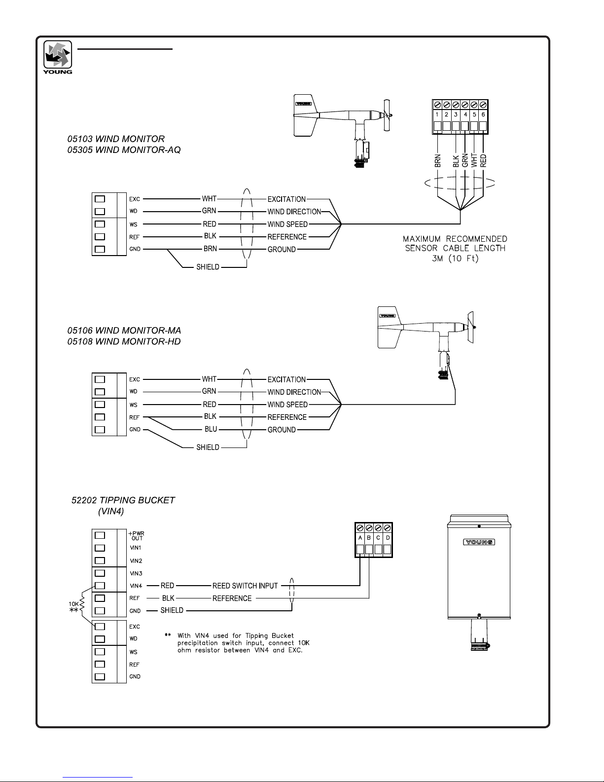
PRECIP and PRECIP POLLED congure VIN4 as a special input to
count tipping bucket precipitation gauge switch closures. (Requires
a 10K ohm resistor from VIN4 to EXC terminal.)
SOFTWARE mode allows output format and other parameters to
be set using serial commands. Please see section 4.0 SERIAL
COMMUNICATION and the SERIAL FORMAT DIAGRAM for more
information.
W2 & W3 JUMPERS determine output connection type. Only one
connection type may be used at a time. Please refer to the WIRING
DIAGRAM for jumper location and connection details.
JUMPERS OUTPUT TYPE
VOUT
Calibrated output for wind speed and direction
OUT1 0-5000mV = 0-100 m/s Wind Speed
OUT2 0-5000mV = 0-360 degrees Wind Direction
232 RS-232 full duplex serial
485 RS-485 half duplex serial

Page 2
32500-90(U)
3.2 COMPASS CALIBRATION
When the 32500 is operated for the rst time, its internal compass must
be calibrated for local conditions. To calibrate the compass, please
follow the steps outlined below.
1. Remove cover from compass. Press and hold CALIBRATE button
for 5 seconds. The CALIBRATE indicator will begin to blink. Refer
to WIRING DIAGRAM to locate CALIBRATE button.
2. Slowly rotate vehicle on which compass is mounted. Steer vehicle in
a tight circle and make TWO complete revolutions. Each revolution
should take at least one minute. THE COMPASS MUST REMAIN
LEVEL DURING CALIBRATION.
3. After two complete revolutions, press and hold CALIBRATE
button until indicator stops blinking. Calibration is now complete.
Calibration parameters are retained when power is removed.
4. Replace cover. Use this procedure to recalibrate compass at any
time.
Serial communication command may also be sent to start and stop
the compass calibration. Please see section 4.2 SERIALCOMMANDS
for details
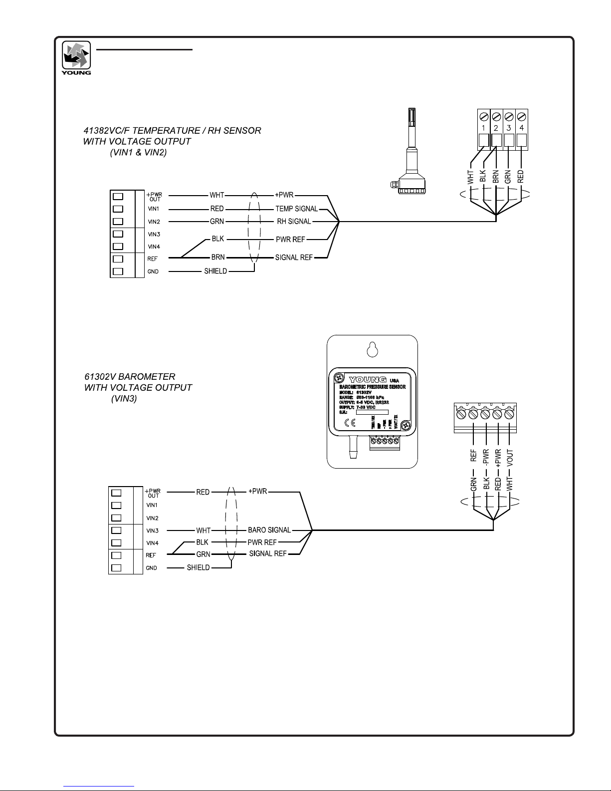
3.3 SIGNAL INPUTS
The 32500 has two special wind speed and direction inputs for
YOUNG wind sensors and four voltage input channels for connection
to other meteorological instruments like temperature, humidity,
barometric pressure, precipitation, or other sensors. Two of the
voltage input channels may also be congured as alternative wind
speed and wind direction inputs for sensors like the Young 86xxx
family. For best performance, sensors should be installed within 3m
(10ft.) of the 32500.
Measurements from the voltage input channels are converted to
numerical values (0-4000) when ASCII, POLLED ASCII, PRECIP,
or PRECIP POLLED are used. VIN1 and VIN2 full scale input is
1000mV DC (serial value = input mV x 4); VIN3 and VIN4 full scale
input is 5000mV (serial value = input mV x 0.8). Note that VIN4 is
used to count tipping bucket precipitation sensor tips when PRECIP
or PRECIP POLLED are used.
When NMEA1 or NMEA2 are used the measurements from the
voltage input channels are converted to following:
VIN1 (0 to 1000mV must = -50 to +50 C), Temperature (C);
VIN2 (0 to 1000mV must = 0 to 100%), Humidity (%);
VIN3, Barometric Pressure (hPa);
VIN4, not used. [Wind speed, (Knots)]
Please refer to SERIAL FORMAT DIAGRAM and WIRING DIAGRAM
in the back of this manual for additional details.
4.0 SERIAL COMMUNICATION
The 32500 uses either full-duplex RS-232 or half-duplex RS-485
signals for serial communication. RS-232 is the most simple and
operates up distances of 30m (100ft). The RS-485 option is prefered
in electrically noisy environments, in applications where multiple units
must be networked, or in NMEA marine applications where RS-485
signals are required.
The full duplex RS-232 connection may transmit and receive serial
data at the same time.
The RS-485 connection is half-duplex meaning the unit cannot
transmit and receive at the same time. The 32500 internally manages
the switch between modes.
Many applications require the 32500 to transmit only. However,
RS-485 applications that require polling the 32500 or sending
commands to it require that the externally connected serial devices
must be capable of managing its own half-duplex switching from
transmit to receive.
At low baud rates with proper cable installation and connections,
transmission distances up to 7km (4mi) are possible using RS-485.
Baud rates of 1200, 4800, 9600, 19.2K, and 38.4K baud are
available. Most jumper-selected output formats force the baud rate
to a predetermined value. All serial signals use 1 start, 8 data, and
1 stop bit. Any externally connected serial device must be set to the
same baud rate as the 32500.
4.1 POLLING
When the serial output format is ASCII POLLED or PRECIP POLLED
(See the SERIAL FORMAT DIAGRAM), the 32500 sends data only
when it receives a serial polling command: “Mc!” where ‘c’ is the
unique address of the unit. The default address is ‘A’ but any alpha or
numeric character may be used (section 4.2 SERIAL COMMANDS).
4.2 SERIAL COMMANDS
Serial commands set operating parameters and report settings.
Jumper W1 must be configured for SOFTWARE mode for serial
command settings to be retained, otherwise default settings
based on jumper configuration will take effect at next power up.
Commands may be sent using a PC and simple communications
programs such as HyperTerm or any other properly configured
serial device. All commands that begin with CMD must end with
a carriage return (ASCII 13).
Commands may be sent at any time but it may be more convenient
to pause the Serial interface output. This is especially necessary with
half-duplex RS-485 communication.
Please refer to the table on the next page for commands and
definitions.
5.0 MAINTENANCE
The 32500 requires no maintenance in normal use.
Periodic inspection is recommended to verify correct operation.
6.0 WARRANTY
This product is warranted to be free of defects in materials and
construction for a period of 12 months from date of initial purchase.
Liability is limited to repair or replacement of defective item. A copy
of the warranty policy may be obtained from R. M. Young Company.
7.0 CE COMPLIANCE
This product complies with European CE requirements for the EMC
Directive. Please note that shielded cable must be used.

Page 3
32500-90(U)
SERIAL COMMANDS TABLE
Command Description Notes:
CMD100 OPERATE Operate Mode
CMD110 PAUSE Pause
CMD200 n DAMPING (0=NONE, 1=FAST, 2=SLOW) Determines the amount of averaging applied to the compass
measurement
CMD210 n FORMAT:
0 ASCII
1 ASCII POLLED
2 NMEA (KTS, DIR)
3 NMEA (KTS, DIR, TEMP, RH, BARO)
4 RMYT
5 PRECIP
6 PRECIP POLLED
7 ASCII 2
9 DIAGNOSTIC
Determines serial output format.
See section 3.1 for more detailed information.
PRECIP formats substitute tipping bucket precipitation counts for
the VIN4 voltage measurement.
ASCII 2 omits VIN measurement values from the output string
CMD220 n OUTPUT RATE (0=15Hz, 1=0.1Hz, 2=2Hz) The rate at which serial data strings are sent.
CMD230 c POLL CHARACTER (0-9, A-Z) Sets the unique, single alpha or numeric character polling address.
CMD240 nn BAUD RATE:
12 = 1200, 48 = 4800, 96 = 9600,
192 = 19200, 384 = 38400
Selects one of several preset baud rates. If you change baud rate
while connected, your external device must also be changed in
order to continue communicating with the 32500
CMD250 n INPUT TYPE (1 = PULSE/POT, 2 = VIN3/VIN4) Determines the type of wind speed and wind direction signal to
use. Type 1 is for standard WS pulse input wind speed and WD
potentiometer wind direction input. Type 2 is for VIN3 (wind
speed) and VIN4 (wind direction). With Type 2 voltage inputs,
0 to 5000mV = 0 to 100 m/s wind speed and 0 to 540 degrees
wind direction. These alternative inputs allow connection to
devices like the Young 86xxx family of 2D Sonic Anemometer
CMD260 nnnn BARO RANGE LOW (mB) Min range of connected Barometer (0.0VDC). Default is 0500 mB.
CMD270 nnnn BARO RANGE HIGH (mB) Max range of connected Barometer (5.0VDC). Default is 1100 mB
CMD280 nnn PROPELLER PITCH (mm/rev) Connected sensor prop pitch. Default is 294 mm/rev (05103/05106).
CMD900 REPORT PARAMETER SETTINGS Shows the current sate of Damping,
Output Format, Output Rate, and Poll Character
CMD910 START COMPASS CALIBRATION Same function as the CALIBRATE button. Section 3.1 COMPASS
CALIBRATION has details regarding the procedure.
CMD920 STOP COMPASS CALIBRATION
X Alternative command to enter OPERATE mode Operate Mode
3xESC Alternative command to PAUSE Pause
3xCNTL-S Alternative command to START calibration Start
3xCNTL-X Alternative command to STOP calibration Stop

Page 4
32500-90(U)
SERIAL OUTPUT FORMATS
MODEL 32500

Page 5
32500-90(U)
WIRING DIAGRAM
MODEL 32500 JUMPER CONFIGURATIONS & POWER

Page 6
32500-90(U)
SERIAL WIRING CONNECTION
MODEL 32500
Typical RS-232 connection to PC
or other device. 32500 jumpers set
for RS-232 ASCII output.
Polled ASCII RS-485 half-duplex serial
connection to YOUNG 26800. Note jumper
conguration on 32500

Page 7
32500-90(U)
WIRING DIAGRAM
Output to 06201 Wind Tracker
Page 8
32500-90(U)
WIRING DIAGRAM
TYPICAL APPLICATION WIRING
Page 9
32500-90(U)
WIRING DIAGRAM
NMEA2 TYPICAL WIRING
WHEN USING NMEA2 FORMAT
SENSORS MUST BE CONNECTED AS SHOWN
FOR PROPER DATA REPORTING

Page 10
32500-90(U)
WIRING CONNECTION
MODEL 32500 with 86000/86106 2D Sonic Anemometer
Other manuals for 32500
3
Table of contents
Other R.M. Young Compass manuals


