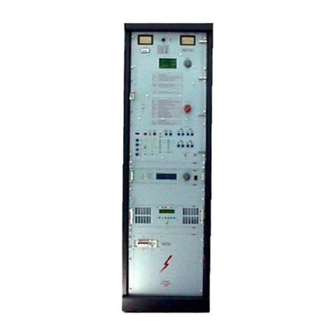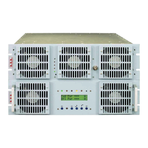
PJ1000M-C
3 / 24UserManual Rev.1.1 -10/11/03
2. Warranty
AnyproductofR.V.R. Elettronica iscoveredbylimitedwarranty.Thewarrantylength
dependsonwetherthepurchaserisaend useror areseller. Ifthepurchaserisaend
user, the warranty period istwo years,andanydfectshallbe communicated to the
manufacturewithintwomonthsfromthediscoveryoftheproblem.Ifthe purchaseris
areseller, the warranty length is one yeard, andanydefectshallbe communicated
tothe manufacturer withineightdaysfrom itsdiscovery.
Forcomponentslike tubesfor poweramplifiers, theoriginalmanufacturer’swarranty
applies.
R.V.R.ElettronicaSpAextendstotheoriginalend-userpurchaserallmanufacturers
warranties which are transferrable and all claims are to be made directly to R.V.R.
perindicatedprocedures.
Warrantyshallnotinclude:
1 damages occurring during the transportantion to R.V.R. Elettronica to perform
servicing;
2 anyunauthorized modification orrepair;
3 Incidental/consequentialdamages as aresultofany defect
4 Nominalnon-incidental defects
5 Re-shipmentcosts or insuranceofthe unit orreplacementunits/parts.
Anydamageto the goods must be reported to the carrier in writing on the shipment
receipt.
Anydiscrepancy or damagediscoveredsubsequent to delivery, shallbereportedto
R.V.R. Elettronica within5(five)daysfromdeliverydate.
Toclaim yourrightsunderthis warranty,you sholdfollowthis procedure:
1 Contact the dealer or distributor where you purchased the unit. Describe the
problemand,so that a possible easy solution can be detected.
Dealers and Distributors are supplied with all the information about problems
that may occur and usually they can repair the unit quicker than what the
manufacturercould do. Very often installingerrors are discovered bydealers.
2 Ifyourdealercannothelpyou,contactR.V.R.Elettronicaandexplaintheproblem.
Ifit is decided to return the unittothefactory, R.V.R. Elettronica will mail you
aregularauthorization withall thenecessaryinstructionstosendbackthegoods.
3 Whenyoureceive theauthorization,youcanreturn theunit.Pack it carefully
for the shipment, preferably using the original packing and seal the package
perfectly. The customer always assumes the risks of loss (i.e., R.V.R. is never
responsiblefor damageorloss), until thepackagereachesR.V.R. premises. For
this reason, we suggest you to insure the goods for the whole value. Shipment
must be effected C.I.F. (PREPAID) to the address specified by R.V.R.’s service
managerontheauthorization
