© 2013 Rabid Elephant
Page 2 of 4
traces on the Eterna PCB. These are located on the top of the
PCB in the gap between the switch and jacks. The needle file
works great. If you ask again, well, it’s your life so do what
you want :D Figure 4 shows where the needle file should go.
Figure 4. File that shizzle.
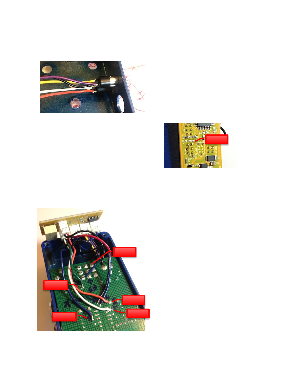
Carefully cut through the first 5 traces (from the left of the PCB
(the side with the ground spring (that’s some top notch
engineering, there, Mr. Black) (oooh, nested parenthesis))) as
shown in Figure 5. Do not cut too deep into the PCB; the traces
are only about 40um thick. You are crazy for doing this,
maybe. Either way, the Rabid Elephant is proud.
Figure 5. Look at my crazy good filing skills.
Now remove R14.
That’s it!
4INSTALLING AND WIRING UP THE MIDI
MidiBrains requires at least a MIDI In jack to be able to receive
MIDI data. Adding a MIDI Thru jack will allow daisy chaining
of multiple MIDI devices across your pedals, which is
extremely convenient and far more compact than using MIDI
DIN connectors. It is recommended you add the MIDI Thru
jack.
Also note that this procedure mounts the MIDI connectivity to
the pedal using additional jacks, which requires drilling two
holes in the pedal somewhere. If you do not wish to drill these
holes in the pedal, you can run one or two (if you want MIDI
Thru) female 3.5mm cables out of the bottom of the pedal and
leave the bottom cover cracked.
4.1 INSTALLING THE MIDI JACKS
Drill a 6mm (15/64”) hole on the input side the enclosure
40.5mm from the outside of the top edge and 10.5mm from
the bottom edge of the pedal (without the cover) for the MIDI
Thru jack. Drill a 2nd 5/16” hole 40.5mm from the outside of
the top edge and 20mm from the bottom edge of the pedal for
the MIDI In jack. The MIDI In jack is the isolated one – you
must install this jack in the hole before soldering on the wires.
I always screw this up for some reason. Noob. It will look
like Figure 6.
Figure 6. Get dem holez.
You may find other locations the jacks will fit. Be certain
there is no possibility of the back of the jack shorting
something out or colliding with other components.
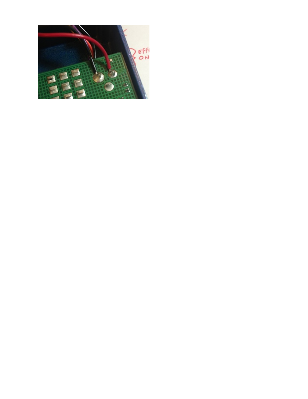
4.2 WIRING UP THE MIDI JACKS
4.2.1 MIDI IN
Connect MidiBrains MIDI IN/THRU Header P1 (ORG) to
MIDI IN 3.5 mm jack ring (gold terminal).
Connect MidiBrains MIDI IN/THRU Header P3 (WHT) to
MIDI IN 3.5 mm jack tip (silver terminal).
4.2.2 MIDI THRU
Connect MidiBrains MIDI IN/THRU Header P2 (YEL) to
MIDI THRU 3.5 mm jack tip (silver terminal).
Connect MidiBrains MIDI IN/THRU Header P4 (PPL) to
MIDI THRU 3.5 mm jack ring (gold terminal).