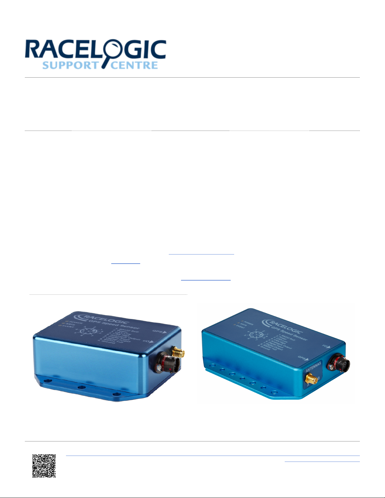
03 - Installing your VBOX Speed Sensor
Mounting
The VBOX Speed Sensor should be securely mounted inside the vehicle, level with the ground. There are holes in the
ground plate that can be used to fasten the Speed Sensor to a suitable location in the vehicle. Make sure that the
surface with the LEDs and pin information is up.
Interfacing with the VBOX Speed Sensor
You can use the VBOX Speed Sensor in several different ways, and it is common for the end-user to integrate the
speed sensor connector into their own wiring harness. You can purchase a mating connector, Deutsch ASDD606-09PN,
from Racelogic for this purpose.
You should connect the GNSS antenna before you connect power to the Speed Sensor. This is because the Speed
Sensor will look for a connected GNSS antenna and automatically adjust its gain for optimum performance from the
connected antenna.
The GNSS antenna supplied with the Speed Sensor is a 5 V active antenna. For the best possible signal quality, it is
important to maintain a clean connection between the antenna and the Speed Sensor. Before you fix the antenna to the
Speed Sensor, make sure that there are no dust particles in either connector. Replacement antennas are
available from your Racelogic distributor.
The antenna is a magnetic mounting type for quick and simple mounting to the vehicle roof. For optimum GNSS signal
reception, make sure that the antenna is fitted to the highest point of the vehicle, away from any obstructions that may
block satellite reception. The GNSS antenna works best with a metal ground plane underneath (a metallic vehicle roof is
perfect for this).
Note that it is important to have a clear sky view when you are using any GNSS equipment. Objects in the surrounding
area, such as tall buildings or trees, can block the GNSS signal and lead to a reduction in the number of satellites that
are being tracked and could introduce reflected signals that can decrease the accuracy of the system. Clouds and other
atmospheric conditions do not affect the performance.
https://en.racelogic.support//Product_Info/Sensors/Single_and_Dual_Antenna_Speed_Sensors/VBOX_Speed_Sensor_User_Guide/
02_-_Speed_Sensor_GPS_Antenna
5