pizzato ST G Series User manual

1/20
Pizzato Elettrica Srl
via Torino, 1
36063 MAROSTICA (VI)
ITALY
e-mail: [email protected]
web site: www.pizzato.com
Phone: +39.0424.470.930
ZE FOG131C19-EU
1 INFORMAZIONI SUL PRESENTE DOCUMENTO
1.1 Funzione
Le presenti istruzioni per l’uso forniscono informazioni su installazione, collegamento
e uso sicuro dei seguenti articoli: ST G••••••.
1.2 A chi si rivolge
Le operazioni descritte nelle presenti istruzioni per l’uso, devono essere eseguite
esclusivamente da personale qualificato, perfettamente in grado di comprenderle, con
le necessarie qualifiche tecnico professionali per intervenire sulle macchine e impianti
in cui saranno installati i dispositivi di sicurezza.
1.3 Campo di applicazione
Le presenti istruzioni per l’uso si applicano esclusivamente ai prodotti elencati nel
paragrafo Funzione e ai loro accessori
1.4 Istruzioni originali
La versione in lingua italiana rappresenta le istruzioni originali del dispositivo. Le
versioni disponibili nelle altre lingue sono una traduzione delle istruzioni originali.
2 SIMBOLOGIA UTILIZZATA
Questo simbolo segnala valide informazioni supplementari.
Attenzione: Il mancato rispetto di questa nota di attenzione può causare rotture
o malfunzionamenti, con possibile perdita della funzione di sicurezza.
3 DESCRIZIONE
3.1 Descrizione del dispositivo
Il dispositivo di sicurezza descritto nelle presenti istruzioni per l’uso è definito in
accordo a EN ISO 14119 come interblocco senza contatto, codificato di tipo 4.
I sensori di sicurezza con tecnologia RFID, a cui si riferiscono le presenti istruzioni
per l’uso, sono dispositivi di sicurezza progettati e realizzati per il controllo di cancelli,
protezioni, carter e ripari in genere, installati a protezione di parti pericolose di
macchine senza inerzia.
3.2 Uso previsto del dispositivo
- Il dispositivo descritto nelle presenti istruzioni per l’uso nasce per essere applicato
su macchine industriali (come definite dalla Direttiva Macchine) per il controllo dello
stato di protezione mobili.
- È vietata la vendita diretta al pubblico di questo dispositivo. L’uso e l’installazione è
riservata a personale specializzato.
- Non è consentito utilizzare il dispositivo per usi diversi da quanto indicato nelle
presenti istruzioni per l’uso.
- Ogni utilizzo non espressamente previsto nelle presenti istruzioni per l’uso è da
considerarsi come utilizzo non previsto da parte del costruttore.
- Sono inoltre da considerare utilizzi non previsti:
a) utilizzo del dispositivo a cui siano state apportate modifiche strutturali, tecniche o
elettriche;
b) utilizzo del prodotto in un campo di applicazione diverso da quanto riportato nel
paragrafo CARATTERISTICHE TECNICHE.
4 ISTRUZIONI DI MONTAGGIO
Attenzione: L’installazione di un dispositivo di protezione non è sufficiente a
garantire l’incolumità degli operatori e la conformità a norme o direttive specifiche
per la sicurezza delle macchine. Prima di installare un dispositivo di protezione è
necessario eseguire un’analisi del rischio specifica secondo i requisiti essenziali di
salute e sicurezza della Direttiva Macchine. Il costruttore garantisce esclusivamente
la sicurezza funzionale del prodotto a cui si riferiscono le presenti istruzioni per l’uso,
non la sicurezza funzionale dell’intera macchina o dell’intero impianto.
4.1 Direzioni d’azionamento
Il dispositivo può essere azionato avvicinando l’azionatore da tutte le direzioni.
I simboli di centraggio marcati sul dispositivo e sull’azionatore devono
essere affacciati quando la protezione è chiusa, indipendentemente dalla direzione
di azionamento.
Art. ST G••••••-G•T Art. ST G••••••-D•T Art. ST G••••••-E•T Art. ST G••••••-L•T
4.2 Scelta del tipo di azionatore
Attenzione: Il dispositivo è disponibile con due tipologie di azionatore RFID:
ad alto livello di codica (articoli SM •1T) oppure a basso livello di codica (articoli
SM •0T). Nel caso sia stato scelto un azionatore a basso livello di codica, durante
l’installazione devono essere rispettate delle specifiche aggiuntive prescritte dalla nor-
ma EN ISO 14119:2013 paragrafo 7.2
Attenzione: Nel caso sia stato scelto un azionatore a basso livello di codifica
eventuali altri azionatori a basso livello di codifica presenti nello stesso luogo dove
è stato installato il dispositivo, devono essere segregati e tenuti sotto stretto control-
lo per evitare l’elusione del dispositivo di sicurezza. Qualora vengano montati nuovi
azionatori a basso livello di codifica, gli azionatori originali a basso livello di codifica,
devono essere smaltiti oppure resi inutilizzabili.
Si consiglia di utilizzare azionatori ad alto livello di codifica in modo da rendere
più flessibile e sicura l’installazione. In questo modo non saranno necessarie scher-
mature del dispositivo, montaggio in zone non accessibili o altre prescrizioni previste
dalla norma EN ISO 14119 per gli azionatori a basso livello di codifica.
Il dispositivo può essere utilizzato anche in abbinamento con gli azionatori
SM D•T, SM E•T e SM L•T, con livello di codica alto o basso, mantenendo inalterati
i livelli di sicurezza.
4.3 Fissaggio del dispositivo e dell’azionatore
Il sensore può essere fissato in
qualsiasi posizione, ruotandolo nel
verso più adatto affinché l’uscita
delle connessioni sia rivolta nella
direzione richiesta dalla particolare
applicazione.
Attenzione: Una volta defini-
to il verso di fissaggio del sensore,
inserire le bussole fornite in dota-
zione nei fori sul lato opposto all’in-
gresso delle viti.
Il sensore e l’azionatore devono
essere sempre fissati con 2 viti M4
con classe di resistenza 4.6 o su-
periore e con sotto testa piano. Le viti devono essere montate con frena filetti di media
resistenza e avere un numero di filetti in presa uguale o superiore al proprio diametro.
Non è ammesso il fissaggio del dispositivo o dell’azionatore con un numero di viti
inferiore a 2. Coppia di serraggio delle viti M4 compresa tra 0,8 e 1,0 Nm.
Attenzione: Come prescritto dalla norma EN ISO 14119 l’azionatore deve esse-
re fissato al telaio della porta in modo inamovibile.
Per un fissaggio corretto possono essere utilizzati anche altri mezzi come rivetti, viti di
sicurezza non smontabili (one-way) o altro sistema di fissaggio equivalente, purché in
grado di garantire un adeguato fissaggio.
Con il dispositivo vengono forniti tappi di sicurezza anti manomissione. L’impiego
dei tappi è considerato una misura adatta per ridurre al minimo la possibilità di smon-
taggio dell’azionatore secondo EN ISO 14119. Pertanto applicando al dispositivo i
tappi in dotazione, si possono utilizzare normali viti per il fissaggio dell’azionatore.
Per le regolazioni non utilizzare un martello, svitare le viti e regolare manualmente il
dispositivo per poi serrarlo in posizione.
4.4 Montaggio di più sistemi sensore - azionatore
50 mm
In caso di installazione di più di un disposi-
tivo di sicurezza sulla stessa macchina, la
distanza di montaggio fra sistemi sensore -
azionatore deve essere almeno di 50 mm.
4.5 Collegamenti elettrici del dispositivo
Versioni a 5 poli
ST G•2••••, ST G•6••••
Connettore M12 Cavo Connessione 1
42
35
1 marrone A1 (+)
2 bianco OS1
3blu A2 (-)
4 nero OS2
5 grigio O3 (a)
Versioni a 8 poli
ST G•3••••, ST G•4••••, ST G•5••••, ST G•7••••, ST G•8••••
Connettore M12 Cavo Connessione 1
2
345
6
7
8
Note
(a) uscita negata per articoli ST G•6••••,
ST G•7••••, ST G•8••••.
(b) per articoli ST G•3••••, ST G•7••••.
(c) per articoli ST G•4••••, ST G•8••••.
(d) per articoli ST G•5••••.
1 bianco A1 (+)
2 marrone IS1
3 verde A2 (-)
4 giallo OS1
5 grigio O3 (a)
6 rosa IS2
7blu OS2
8 rosso
non connesso (b)
I3 (c)
EDM (d)
Legenda:
A1-A2 = alimentazione I3 = ingresso di programmazione
IS1-IS2 = ingressi sicuri O3 = uscita di segnalazione
OS1-OS2 = uscite sicure EDM = ingresso monitoraggio contattori esterni
4.6 Punti di intervento sensore RFID
Portando l’azionatore all’interno della zona sicura di azionamento (area grigio scuro),
il sensore abilita le uscite sicure (LED acceso verde).
Allontanando l’azionatore dalla zona sicura, il sensore mantiene abilitate le uscite
sicure e, mediante il lampeggio del LED con colore giallo, segnala l’ingresso dell’azio-
natore nella zona limite di azionamento (area grigio chiaro).
All’uscita dell’azionatore dalla zona limite di azionamento, il sensore disabilita le usci-
te (LED acceso giallo).
Attenzione: Le distanze di attuazione/rilascio del dispositivo possono essere
influenzate dalla presenza di materiale conduttivo o magnetico nelle vicinanze del
sensore. Le distanze utili di attuazione e rilascio devono sempre essere verificate
dopo il montaggio.

2/20
Aree di attivazione per azionatori SM G•T, SM D•T, SM L•T
25
20
15
10
5
25
20
15
10
5
0 5-5 10-10-15-20 15 20 0 5-5 10-10-15-20 15 20
(mm) (mm)
(mm)(mm)
Aree di attivazione per azionatori SM E•T
(mm)
(mm)(mm)
30
25
20
15
10
5
30
25
20
15
10
5
(mm)
0 5-5 10-10-15-20 15 20 0 5-5 10-10-15-20 15 20
Legenda:
Distanza di intervento nominale sn(mm)
Distanza di rilascio nominale snr (mm)
Nota: L’andamento delle aree di attivazione è indicativo, l’eventuale applicazione su
superfici metalliche può ridurre le distanze di intervento.
5 FUNZIONAMENTO
5.1 Definizioni
Stati del sensore:
- OFF: il sensore è spento, non alimentato.
- POWER ON: stato immediatamente successivo all’accensione nel quale il sensore com-
pie dei test interni.
- RUN: stato nel quale il sensore è in funzionamento normale.
- ERROR: stato di sicurezza nel quale le uscite sicure vengono disattivate. Indica la
presenza di un guasto interno o esterno al dispositivo, come ad esempio:
- un cortocircuito tra le uscite sicure (OS1, OS2);
- un cortocircuito tra un’uscita sicura e massa oppure;
- un cortocircuito tra un’uscita sicura e la tensione di alimentazione;
Per uscire da questo stato è necessario riavviare il sensore.
- Funzione EDM (External Device Monitoring) - se presente: è una funzione che per-
mette al dispositivo di monitorare lo stato di contattori esterni. L’attivazione/disattiva-
zione dei contattori esterni deve seguire le uscite di sicurezza del sensore ST entro un
tempo prestabilito (vedi paragrafo CARATTERISTICHE TECNICHE).
5.2 Descrizione funzionamento generale
f2
f1 f3
f0
OS1
OS2
IS2
IS1
O3
A2A1 LED
RGB
I3 /
EDM f4
LED
CONTROLLER
Dopo esser stato correttamente installato
seguendo le presenti istruzioni, il sensore
può essere alimentato. Lo schema rappre-
senta le funzioni logiche che interagiscono
all’interno del sensore.
Nello stato iniziale di POWER ON la funzio-
ne f0 del sensore esegue un’autodiagnosi
interna che, se terminata con successo,
porta il dispositivo nello stato RUN. Se il test
non è superato il sensore entra nello stato
di ERROR.
Lo stato RUN è di funzionamento normale:
la funzione f2 verifica la presenza dell’azio-
natore nell’area di attivazione sicura.
La funzione f3 attiva le uscite sicure OS1 e
OS2 a seconda della versione del sensore:
- nelle versioni senza ingressi sicuri IS1 e
IS2 (ST G•2••••, ST G•6••••) è sufciente la
presenza dell’azionatore;
- nelle versioni con ingressi sicuri IS1 e IS2 (ST G•3••••, ST G•4••••, ST G•7••••, ST G•8••••)
viene verificata la presenza dell’azionatore e l’attivazione degli ingressi IS1, IS2;
- nelle versioni con EDM (ST G•5••••) viene vericata la presenza dell’azionatore,
l’attivazione degli ingressi IS1, IS2 e la presenza del segnale di retroazione dei con-
tattori esterni.
Durante lo stato RUN, la funzione f0 esegue ciclicamente dei test interni al fine di evi-
denziare eventuali guasti. Il rilevamento di un qualsiasi errore interno porta il sensore
nello stato ERROR (LED acceso con colore rosso, fisso o lampeggiante, secondo il
tipo di errore) che prevede la disattivazione immediata delle uscite sicure da parte
della funzione f3. Lo stato ERROR può essere raggiunto anche nel caso si verifichino
dei cortocircuiti tra le uscite sicure (OS1, OS2) oppure il cortocircuito di un’uscita
verso massa o verso la tensione di alimentazione. Anche in questo caso la funzione
f3 disattiva le uscite sicure e lo stato di errore viene segnalato dalla corrispondente
sequenza di lampeggi del LED.
L’uscita di segnalazione O3, a seconda della versione scelta, si attiva o si disattiva du-
rante lo stato RUN in corrispondenza del rilevamento dell’azionatore all’interno dell’a-
rea di attivazione, indipendentemente dallo stato degli eventuali ingressi IS1 e IS2.
La funzione f4 monitora lo stato di attivazione dell’ingresso I3 (versioni ST G•4•••• e
ST G•8••••) o EDM (versioni ST G•5••••):
- nelle versioni con ingresso I3 per la programmazione dell’azionatore, quando l’in-
gresso è attivo e il dispositivo è in stato RUN, la funzione f4 attiva lo stato di program-
mazione dell’azionatore (vedi paragrafo SOSTITUZIONE DELL’AZIONATORE);
- nelle versioni con ingresso EDM la funzione f4 controlla la coerenza del segnale
EDM durante i cambiamenti di stato e quando le uscite sicure sono spente (vedi
paragrafo DESCRIZIONE FUNZIONAMENTO DELLE VERSIONI CON INGRESSO
EDM).
Le informazioni derivanti dagli stati delle funzioni f0, f1, f2, f3, f4 vengono processate
e comunicate all’utilizzatore mediante le sequenze di accensioni e le modifiche della
colorazione dei LED RGB esterni del dispositivo, secondo le modalità descritte nel
paragrafo STATI DI FUNZIONAMENTO.
5.3 Descrizione funzionamento delle versioni con ingressi sicuri IS1 e IS2 (arti-
coli ST G•3••••, ST G•4••••, ST G•5••••, ST G•7••••, ST G•8••••)
La funzione f1 valuta lo stato degli ingressi IS1, IS2.
Gli ingressi IS1 e IS2 sono monitorati oltre che per il loro stato, anche per la loro
coerenza: normalmente gli ingressi sono azionati in modo simultaneo. In caso di di-
sattivazione di uno solo dei due ingressi, il sensore disattiva le uscite sicure e segnala
una condizione di non coerenza degli ingressi mediante la corrispondente sequenza
di accensione del LED (vedi paragrafo STATI DI FUNZIONAMENTO).Entrambi gli
ingressi devono essere disattivati, per poi essere riattivati, affinché le uscite sicure
possano essere nuovamente attive.
5.4 Descrizione funzionamento delle versioni con ingresso EDM (artico-
li ST G•5••••)
Mediante la funzione f4 viene eseguito il controllo dei contatti NC di contattori o relè
a guida forzata comandati dalle uscite sicure del sensore stesso; tale verifica viene
eseguita dal sensore monitorando l’ingresso EDM (External Device Monitoring). Con
ingressi sicuri attivi e azionatore in zona di attivazione, le uscite di sicurezza sono
attivate solo quando l’ingresso EDM è attivo. All’attivazione delle uscite sicure il di-
spositivo verifica che l’ingresso EDM si disattivi entro il tempo tEDM. Allo spegnimento
delle uscite sicure il dispositivo verifica che il segnale EDM si riattivi entro il tempo tEDM.
Nel caso in cui sia superato il tempo massimo tEDM il sistema entra in stato di ERROR,
disattivando le uscite sicure (nel caso siano attive) e segnalando l’errore mediante la
corrispondente sequenza di accensione del LED (vedi paragrafo STATI DI FUNZIO-
NAMENTO).
5.5 Connessione in serie con moduli di sicurezza
Nel caso si utilizzi un sensore sprovvisto di ingresso EDM, le uscite di sicurezza OS1
e OS2 devono essere collegate ad un modulo di sicurezza o ad un PLC di sicurezza.
Il dispositivo è inoltre dotato di un’uscita di segnalazione O3 che viene attivata (negli
articoli ST G•2••••, ST G•3••••, ST G•4••••) o disattivata (negli articoli ST G•6••••,
ST G•7••••, ST G•8••••) quando il rispettivo riparo è chiuso. Questa informazione può
essere gestita da un PLC a seconda delle necessità specifiche del sistema realizzato,
oppure da un modulo di sicurezza programmabile della serie CS MP di Pizzato
Elettrica, che permette la gestione delle uscite sia di sicurezza che di segnalazione.
Esempio di collegamento
con modulo di sicurezza e PLC
Esempio di collegamento
con modulo di sicurezza programmabile
ST •••••••
ST •••••••
ST •••••••
PLC
O3
O3
O3
+ Vcc
Ixx Ixx
OS1 OS2
IS1 IS2
IS1 IS2
IS1 IS2
OS1 OS2
OS1 OS2
SM ••TSM ••TSM ••T
ST •••••••
ST •••••••
ST •••••••
O3
O3
O3
+ Vcc
Ixx Ixx
OS1 OS2
IS1 IS2
IS1 IS2
IS1 IS2
OS1 OS2
OS1 OS2
SM ••TSM ••TSM ••T
È possibile installare più sensori connessi in cascata fino ad un massimo di 32 dispo-
sitivi, mantenendo la categoria di sicurezza 4 / PL e secondo EN ISO 13849-1 e il
livello di integrità SIL CL 3 secondo EN 62061.
Verificare che i valori di PFH ed MTTFd del sistema costituito dalla cascata di dispo-
sitivi e l’intero circuito di sicurezza, soddisfino i requisiti del livello SIL/PL richiesto
dall’applicazione.
Con questa modalità di collegamento si devono rispettare le seguenti avvertenze.
- Collegare gli ingressi del primo dispositivo della catena alla tensione di alimenta-
zione.
- Le uscite di sicurezza OS1 e OS2 dell’ultimo dispositivo della catena devono essere
collegate al circuito di sicurezza della macchina.
- Nel caso in cui venga utilizzato un modulo di sicurezza, verificare che le caratteri-
stiche delle uscite sicure OS1/OS2 siano compatibili con gli ingressi del modulo di
sicurezza (vedi paragrafo INTERFACCIAMENTO).
- Rispettare i limiti sulla capacità parassita delle linee d’uscita, indicati nelle caratteri-
stiche elettriche (vedi paragrafo CARATTERISTICHE TECNICHE).
- Verificare che il tempo di risposta della cascata rispetti i requisiti della funzione di
sicurezza da realizzare.
- Il tempo di risposta della catena deve essere calcolato tenendo conto del tempo di
risposta di ciascun dispositivo.
Il numero massimo di 32 dispositivi connessi in cascata dipende anche dalla
lunghezza e dalla sezione dei conduttori utilizzati tra i dispositivi. Il nostro servizio di
supporto tecnico può fornire assistenza nel calcolo delle distanze massime e sezioni
minime dei conduttori da utilizzare per un corretto funzionamento dei dispositivi colle-
gati in cascata (vedi paragrafo SUPPORTO).
Modulo di sicurezza
Pizzato Elettrica
serie CS
Modulo di sicurezza programmabile
Pizzato Elettrica
serie CS MP

3/20
5.6 Connessione EDM (External Device Monitoring)
ST G•51•••
ST G•310••
ST G•310••
PLC
IS1
K1 K2
O3
SM ••TSM ••TSM ••T
O3
O3
EDM
+
+
IS2
OS1 OS2
IS1 IS2
IS1 IS2
OS1 OS2
OS1 OS2
Per alcune specifiche applicazioni, in
alternativa al collegamento con moduli
di sicurezza, è possibile utilizzare l’arti-
colo ST G•51••• con la verica dei con-
tatti NC dei relè a guida forzata (K1, K2)
connessi all’ingresso EDM, installato
come ultimo sensore della catena.
5.7 Interfacciamento
Collegamenti con i moduli di sicurezza CS AR-08••••
Configurazione ingressi con start controllato
2 canali / Categoria 4 / fino a SIL 3 / PL e
Versioni a 5 poli Versioni a 8 poli
S33
S21 S22 S35 S34 A2
S52
S12
A1
-
+
OS2
A1
+
A2
-
ST
CS
OS1
S33
S21 S22 S35 S34 A2
S52
S12
A1
-
+
OS2
OS1
IS2
IS1
A1
+
A2
-
ST
CS
Collegamenti con i moduli di sicurezza CS AR-05•••• / CS AR-06••••
Congurazione ingressi con start manuale (CS AR-05••••) o start controllato (CS AR-06••••)
2 canali / Categoria 4 / fino a SIL 3 / PL e
Versioni a 5 poli Versioni a 8 poli
S21 S22 S34 A2
A1
-
+
S52
S12
OS2
OS1
A1
+
A2
-
ST
CS
S21 S22 S34 A2
A1
-
+
S52
S12
OS2
OS1
IS2
IS1
A1
+
ST
CS
A2
-
Collegamenti con i moduli di sicurezza CS AT-0••••• / CS AT-1•••••
Configurazione ingressi con start controllato
2 canali / Categoria 4 / fino a SIL 3 / PL e
Versioni a 5 poli Versioni a 8 poli
S33
S21 S22 S35 S34 A2
A1
-
+
S31
S12
OS2
OS1
A1
+
A2
-
ST
CS
S33
S21 S22 S35 S34 A2
A1
-
+
S31
S12
OS2
OS1
IS2
IS1
A1
+
A2
-
ST
CS
Collegamenti con i moduli di sicurezza CS MF••••0, CS MP••••0
Le connessioni variano in funzione del programma del modulo
Categoria 4/ fino a SIL 3 / PL e
Versioni a 5 poli Versioni a 8 poli
Ixx
Ixx
OS2
OS1
A1
+
OS2
OS1
A1
+
Ixx
Ixx
A2
-
A2
-
ST ST
CS
Ixx
Ixx
OS2
OS1
IS2
IS1
A1
+
OS2
OS1
IS2
IS1
A1
+
Ixx
Ixx
A2
-
A2
-
ST ST
CS
Collegamenti con contattori esterni (solo versioni con EDM)
K1
K2
-
-
+
A1 IS1
OS1 OS2
IS2 A2
+
-
ST G•51••• EDM
Gli articoli ST G•5•••• devono essere
collegati ai contattori con guida forzata di
uscita, come da schema a lato. Il sensore
così connesso può essere classificato
come dispositivo per circuito di comando
fino a PDF-M (EN 60947-5-3)
Attenzione: nel caso in cui alle
uscite di sicurezza OS si colleghi diretta-
mente un contattore di sicurezza, si pre-
scrive l’utilizzo di diodi a commutazione
veloce collegati in parallelo alle bobine di
detti contattori.
Collegamenti con moduli di espansione Pizzato Elettrica (es. CS ME-03••••)
(solo versioni ST G•5••••)
OS2
+
-
ST G•51•••
EDM
A2
A1
A2
IS2
IS1
OS1
OS2
OS1
EDMEDM
5.8 Stati di funzionamento
Sul sensore è presente un LED di segnalazione multicolore
che, attraverso sequenze di accensioni, lampeggi e variazio-
ni di colore, segnala all’utilizzatore i diversi stati di funziona-
mento del dispositivo oltre ad eventuali avvisi ed errori riguar-
danti i componenti elettronici interni.
Il LED è visibile su entrambi i lati del sensore, indipendente-
mente dal verso di montaggio del dispositivo.
Gli stati predefiniti di funzionamento del sensore (OFF, RUN, ERROR, SET) sono
indicati dal led acceso con luce fissa.
Sequenza accensione LED Stato
sensore Descrizione
OFF Sensore spento.
GN
RUN Stato normale di funzionamento con uscite sicure
accese. Nessun errore o avviso presente.
YE
RUN Stato normale di funzionamento con uscite sicure
spente. Nessun errore o avviso presente.
VT
SET Stato di acquisizione nuovo azionatore.
RD
ERROR Stato di errore interno al dispositivo.
Tabella 1: Stati predefiniti di funzionamento
Nel caso in cui si verifichi un evento di tipo ERROR il led alterna ciclicamente la luce
fissa corrispondente allo stato ERROR (vedi tabella 1) con una delle sequenze di
lampeggi riportate in tabella 2, ognuna corrispondente a un diverso tipo di messaggio.
Sequenza accensione LED Stato
sensore Descrizione Prio-
rità
RD RD RD
ERROR Errore temperatura: la temperatura del sen-
sore è fuori dai limiti ammessi. 9
RD RD RD RD
ERROR Errore tensione: la tensione di alimentazione
del sensore è fuori dai limiti ammessi. 8
RD RD YE RD
ERROR Cortocircuito tra le uscite sicure OS1 e OS2. 7
Tabella 2: Messaggi di tipo ERROR
Nel caso in cui si verifichi un evento di tipo WARNING, il led alterna ciclicamente la
luce fissa dell’attuale stato di funzionamento (vedi tabella 1) con la corrispondente
sequenza di lampeggio riportata in tabella 3.
Sequenza accensione LED Stato
sensore Descrizione Prio-
rità
RD
WARNING Avviso temperatura: la temperatura del sen-
sore è vicina ai limiti ammessi. 6
RD RD
WARNING Avviso tensione: la tensione di alimentazione
è vicina ai limiti ammessi. 5
YE YE
WARNING Ingressi IS1 e IS2 non presenti. 4
YE GN
WARNING Ingressi IS1 e IS2 non coerenti. 3
YE
WARNING L’azionatore si trova nell’area limite di rileva-
mento. 2
Tabella 3: Messaggi di tipo WARNING
Legenda: GN = verde RD = rosso YE = giallo
BU = blu VT = viola
Gli eventi di tipo WARNING sono generalmente reversibili. Gli eventi di tipo
ERROR non sono reversibili: il dispositivo non rientra dall’errore, ma deve essere
spento e deve essere risolta la causa dell’errore prima di rimetterlo nuovamente in
funzione.
Nel caso fossero presenti contemporaneamente più eventi di tipo ERROR o
WARNING, è visualizzato soltanto quello con priorità più alta. Ad esempio nel caso
di avviso di temperatura e avviso di tensione, viene visualizzata solo la sequenza di
segnalazione relativa alla temperatura; la sequenza di avviso tensione è visualizzata
solo quando quella di temperatura smette di essere attiva, ovvero quando la
temperatura esce dalla soglia di alert.
Modulo di espansione
Pizzato Elettrica
CS ME-03••••

4/20
5.9 Ingresso di reset
Tramite l’ingresso I3 è possibile resettare i seguenti stati di errore dovuti a guasto
esterno al dispositivo:
- un cortocircuito o un carico eccessivo delle uscite sicure (OS1, OS2),
- un cortocircuito tra un’uscita sicura e la tensione di alimentazione.
5.10 Sostituzione dell’azionatore (solo per articoli ST G•4••••, ST G•8••••)
Attenzione: Il costruttore della macchina deve permettere di accedere alla
modalità di programmazione del sensore solamente al personale abilitato.
Tramite l’ingresso I3 è possibile in qualsiasi momento sostituire l’azionatore codificato
con un secondo azionatore. Questa operazione risulta ripetibile un numero illimitato di
volte. A programmazione avvenuta il sensore riconoscerà solo il codice dell’azionatore
corrispondente all’ultima programmazione effettuata.
1) Alimentare il sensore alla tensione nominale. Il sensore esegue dei test
interni. Il LED si accende secondo le modalità descritte nel paragrafo STATI DI
FUNZIONAMENTO.
2) Attivare l’ingresso di programmazione I3, alimentandolo con la tensione Ue1 (vedi
paragrafo CARATTERISTICHE TECNICHE). Il led si accende con colore viola ad
indicare l’attesa del nuovo codice da memorizzare.
3) Avvicinare il nuovo azionatore al sensore, allineando i simboli di centraggio. Il led
emette due lampeggi di colore verde quando la programmazione è andata a buon
fine.
4) Disattivare l’ingresso di programmazione I3: il sensore si riavvia automaticamente e
riesegue i test interni per poi portarsi nello stato di funzionamento RUN.
Il secondo azionatore dovrà essere adeguatamente fissato alla protezione come
previsto nel paragrafo ISTRUZIONI DI MONTAGGIO. Ad operazione effettuata
eseguire un controllo del riconoscimento del nuovo azionatore programmato ed
eseguire la sequenza di prove funzionali previste nelle presenti istruzioni per l’uso.
Questa operazione non deve essere eseguita come operazione di riparazione o
manutenzione. Nel caso il dispositivo smetta di funzionare correttamente sostituire
tutto il dispositivo e non solo l’azionatore.
L’operazione di programmazione dell’azionatore è eseguibile sia con gli ingressi
sicuri non attivi, sia con gli ingressi sicuri attivi.
6 AVVERTENZE PER UN CORRETTO USO
6.1 Installazione
Attenzione: L’installazione deve essere eseguita esclusivamente da personale
qualificato. Le uscite sicure OS1 e OS2 del dispositivo devono essere collegate al
circuito di sicurezza della macchina. L’uscita di segnalazione O3 non è un’uscita sicura
e non può essere utilizzata singolarmente in un circuito di sicurezza per determinare
lo stato sicuro di riparo chiuso.
- Non sollecitare il dispositivo con flessioni o torsioni.
- Non modificare il dispositivo per nessun motivo.
- Non superare le coppie di serraggio indicate nelle presenti istruzioni per l’uso.
- Il dispositivo svolge una funzione di protezione degli operatori. L’installazione inade-
guata o le manomissioni possono causare gravi lesioni alle persone fino alla morte,
danni alle cose e perdite economiche.
- Questi dispositivi non devono essere né aggirati, né rimossi, né ruotati o resi ineffi-
caci in altra maniera.
- Se la macchina dove il dispositivo è installato viene utilizzata per un uso diverso da
quello specificato, il dispositivo potrebbe non fornire una protezione efficace per
l’operatore.
- La categoria di sicurezza del sistema (secondo EN ISO 13849-1) comprendente il
dispositivo di sicurezza, dipende anche dai componenti esterni ad esso collegati e
dalla loro tipologia.
- Prima dell’installazione assicurarsi che il dispositivo sia integro in ogni sua parte.
- Evitare piegature eccessive dei cavi di connessione per impedire cortocircuiti e in-
terruzioni.
- Non verniciare o dipingere il dispositivo.
- Non forare il dispositivo.
- Non utilizzare il dispositivo come supporto o appoggio per altre strutture come cana-
line, guide di scorrimento o altro.
- Prima della messa in funzione, assicurarsi che l’intera macchina (o il sistema) sia
conforme alle norme applicabili e ai requisiti della direttiva Compatibilità Elettroma-
gnetica.
- La superficie di montaggio del dispositivo deve essere sempre piana e pulita.
- La documentazione necessaria per una corretta installazione e manutenzione è
sempre disponibile nelle seguenti lingue: inglese, francese, tedesco, italiano.
- Nel caso l’installatore non sia in grado di comprendere pienamente la documentazio-
ne, non deve procedere con l’installazione del prodotto e può chiedere assistenza
(vedi paragrafo SUPPORTO).
- Prima della messa in servizio e periodicamente, verificare la corretta commutazione
delle uscite e il corretto funzionamento del sistema composto dal dispositivo e dal
circuito di sicurezza associato.
- Non eseguire saldature ad arco, saldature al plasma o qualsiasi processo in grado
generare campi elettromagnetici di intensità superiore ai limiti prescritti dalle norme,
in prossimità del dispositivo, nemmeno quando questo è spento. Nel caso si doves-
sero eseguire operazioni di saldatura in prossimità di un dispositivo precedentemen-
te installato, è necessario allontanarlo preventivamente dall’area di lavoro.
- Allegare sempre le presenti istruzioni per l’uso nel manuale della macchina in cui il
dispositivo è installato.
- La conservazione delle presenti prescrizioni d’impiego deve permettere la loro con-
sultazione per tutto il periodo di utilizzo del dispositivo.
6.2 Non utilizzare nei seguenti ambienti
- In ambienti dove l’applicazione provoca collisioni, urti o forti vibrazioni al dispositivo.
- In ambienti con presenza di polveri o gas esplosivi o infiammabili.
- In ambienti dove è possibile la formazione di manicotti di ghiaccio sul dispositivo.
- In ambienti fortemente chimico aggressivi, dove i prodotti utilizzati che vengono a
contatto con il dispositivo, possono comprometterne l’integrità fisica o funzionale.
6.3 Arresto meccanico
Attenzione: La porta deve essere sempre dotata di un arresto meccanico
indipendente in chiusura a fondo corsa.
Non utilizzare il dispositivo come arresto meccanico della porta. L’azionatore non deve
urtare il sensore.
6.4 Manutenzioni e prove funzionali
Attenzione: Non smontare o tentare di riparare il dispositivo. In caso di anomalia
o guasto sostituire l’intero dispositivo.
Attenzione: In caso di danneggiamenti o di usura si deve sostituire il dispositivo
completo e anche il suo azionatore. Con il dispositivo deformato o danneggiato il
funzionamento non è garantito.
- È responsabilità dell’installatore stabilire la sequenza di prove funzionali a cui
sottoporre il dispositivo prima della messa in funzione della macchina e durante gli
intervalli di manutenzione.
- La sequenza delle prove funzionali può variare in base alla complessità della
macchina e dal suo schema circuitale, pertanto la sequenza di prove funzionali sotto
riportata è da considerarsi minimale e non esaustiva.
- Eseguire prima della messa in funzione della macchina e almeno una volta all’anno
(o dopo un arresto prolungato) la seguente sequenza di verifiche:
1) Aprire la protezione con la macchina in movimento. La macchina si deve arrestare
immediatamente. Il tempo di arresto della macchina dovrà essere sempre inferiore
al tempo impiegato dall’operatore per aprire la protezione e raggiungere gli elementi
pericolosi.
2) Con la protezione aperta tentare di avviare la macchina. La macchina non deve
avviarsi.
3) Verificare il corretto allineamento tra azionatore e dispositivo.
4) Verificare che l’insieme delle parti esterne non sia danneggiato. Se si rilevano danni
sostituire completamente il dispositivo.
5) L’azionatore deve essere saldamente bloccato alla porta, verificare che non sia
possibile con utensili in uso all’operatore della macchina, scollegare l’azionatore dalla
porta.
- Il dispositivo nasce per applicazioni in ambienti pericolosi, pertanto il suo utilizzo
è limitato nel tempo. Trascorsi 20 anni dalla data di produzione, il dispositivo deve
essere sostituito completamente, anche se ancora funzionante. La data di produzione
è posta vicino al codice prodotto (vedi paragrafo MARCATURE).
6.5 Cablaggio
Attenzione: Verificare che la tensione di alimentazione sia corretta prima di
alimentare il dispositivo.
- Mantenere il carico all’interno dei valori indicati nelle categorie d’impiego elettriche.
- Collegare e scollegare il dispositivo solamente in assenza di tensione.
- Non aprire il dispositivo per nessun motivo.
- Scaricare l’elettricità statica prima di maneggiare il prodotto, toccando una massa
metallica connessa a terra. Forti scariche elettrostatiche potrebbero danneggiare il
dispositivo.
- Alimentare l’interruttore di sicurezza e gli altri dispositivi ad esso connessi da un’uni-
ca sorgente di tipo SELV ed in conformità con le relative norme.
- Collegare sempre il fusibile di protezione (o un dispositivo equivalente) in serie all’a-
limentazione per ogni dispositivo.
- Durante e dopo l’installazione non tirare i cavi elettrici collegati al dispositivo.
- Per i dispositivi con cavo integrato l’estremità libera del cavo, se priva di connettore,
deve essere adeguatamente collegata all’interno di una custodia protetta. Il cavo
deve essere adeguatamente protetto da tagli, urti, abrasioni, ecc.
6.6 Prescrizioni aggiuntive per applicazioni di sicurezza con funzioni di
protezione delle persone
Fermo restando tutte le precedenti prescrizioni, nel caso in cui i dispositivi vengano
installati con funzione di protezione delle persone, vanno rispettate le seguenti pre-
scrizioni aggiuntive.
- L’impiego implica il rispetto e la conoscenza delle norme EN 60947-5-3,
EN ISO 13849-1, EN 62061, EN 60204-1, EN ISO 14119, EN ISO 12100.
6.7 Limiti di utilizzo
- Utilizzare il dispositivo seguendo le istruzioni, attenendosi ai suoi limiti di funziona-
mento e impiegandolo secondo le norme di sicurezza vigenti.
- I dispositivi hanno dei specifici limiti di applicazione (temperatura ambiente minima
e massima, durata meccanica, grado di protezione IP, ecc.) Questi limiti vengono
soddisfatti dal dispositivo solo se presi singolarmente e non in combinazione tra loro.
- La responsabilità del costruttore è esclusa in caso di:
1) impiego non conforme alla destinazione;
2) mancato rispetto delle presenti istruzioni o delle normative vigenti;
3) montaggio non eseguito da persone specializzate e autorizzate;
4) omissione delle prove funzionali.
- Nei casi di applicazione sotto elencati, prima di procedere con l’installazione, contat-
tare l’assistenza tecnica (vedi paragrafo SUPPORTO):
a) in centrali nucleari, treni, aeroplani, automobili, inceneritori, dispositivi medici o
comunque in applicazioni nelle quali la sicurezza di due o più persone dipenda dal
corretto funzionamento del dispositivo;
b) casi non citati nelle presenti istruzioni per l’uso.

5/20
7 MARCATURE
Il dispositivo è provvisto di marcatura posizionata all’esterno in maniera visibile. La
marcatura include:
- Marchio del produttore
- Codice del prodotto
- Numero di lotto e data di produzione. Esempio: A19 ST1-123456. La prima lettera
del lotto indica il mese di produzione (A = Gennaio, B = Febbraio, ecc.) La seconda
e terza cifra indicano l’anno di produzione (19 = 2019, 20 = 2020, ecc.)
8 CARATTERISTICHE TECNICHE
8.1 Custodia
Custodia in tecnopolimero rinforzato con fibra di vetro, autoestinguente.
Versioni con cavo integrato 5 x 0,25 mm2o 8 x 0,25 mm2, lunghezza 2 m, altre
lunghezze a richiesta.
Versioni con connettore M12 in plastica o in acciaio inox.
Versioni con cavo lunghezza 0,2 m e connettore M12 integrato, altre lunghezze a
richiesta.
Lunghezza massima dei cavi di collegamento: 50 m.
(La lunghezza del cavo e la sua sezione alterano gli impulsi di disattivazione sulle uscite sicure.
Verificare che la capacità tra i conduttori del cavo di collegamento sia inferiore a quella ammessa
nelle caratteristiche elettriche delle uscite sicure)
Grado di protezione: IP67 secondo EN 60529, IP69K secondo ISO 20653
(Proteggere i cavi da getti diretti ad alta pressione e temperatura)
8.2 Generali
Per applicazioni di sicurezza fino a: SIL 3 secondo EN 62061
PL e, cat.4 secondo EN ISO 13849-1
Interblocco senza contatto, codificato: tipo 4 secondo EN ISO 14119
Livello di codifica secondo EN ISO 14119: alto con azionatori SM •1T
basso con azionatori SM •0T
Parametri di sicurezza:
MTTFD: 1551 anni
PFHD: 1,19E-09
DC: High
Mission time: 20 anni
Temperatura di esercizio: -25 … +70 °C (articoli ST G••••••)
-35 … +85 °C (articoli ST G••••MK-T8)
Temperatura di stoccaggio: -35 … +85 °C
Tenuta alle vibrazioni: 10 gn (10...150 Hz) secondo IEC 60068-2-6
Tenuta agli urti: 30 gn; 11 ms secondo EN 60068-2-27
Grado d’inquinamento 3
8.3 Caratteristiche elettriche alimentazione
8.3.1 Caratteristiche elettriche alimentazione
Tensione nominale d’impiego Ue: 24 Vdc
Tolleranza sulla tensione di alimentazione: ± 15% di Ue
Corrente d’impiego alla tensione Ue:
minima: 20 mA
con tutte le uscite alla massima potenza: 550 mA
Tensione nominale di isolamento Ui: 32 Vdc
Tensione di tenuta ad impulso nominale Uimp: 1,5 kV
Fusibile di protezione esterno: 1 A tipo Gg oppure dispositivo equivalente
Categoria di sovratensione: III
8.3.2 Caratteristiche elettriche ingressi IS1/IS2/I3/EDM
Tensione nominale d’impiego Ue1: 24 Vdc
Corrente nominale assorbita: 2,5 mA
Tempo di commutazione stato EDM (tEDM): 500 ms
8.3.3 Caratteristiche elettriche uscite sicure OS1/OS2
Tensione nominale d’impiego Ue2: 24 Vdc
Tipo di uscita: OSSD tipo PNP
Corrente massima per uscita Ie2: 0,2 A
Corrente minima per uscita Im2: 0,5 mA
Corrente termica Ith2: 0,2 A
Categoria d’impiego: DC13; Ue2 = 24 Vdc, Ie2 = 0,2 A
Rilevamento cortocircuiti: Sì
Protezione contro sovracorrenti: Sì
Fusibile di protezione interno ripristinabile: 0,3 A
Durata degli impulsi di disattivazione sulle uscite sicure: < 300 μs
Capacità ammessa tra uscita e uscita: < 200 nF
Capacità ammessa tra uscita e massa: < 200 nF
Tempo di risposta (trI) alla disattivazione degli ingressi IS1 o IS2: < 15 ms
Tempo di risposta (trA) all’allontanamento dell’azionatore: < 50 ms
Tempo di disponibilità: 2 s
8.3.4 Caratteristiche elettriche uscita di segnalazione O3
Tensione nominale d’impiego Ue3: 24 Vdc
Tipo di uscita: PNP
Corrente massima per uscita Ie3: 0,1 A
Categoria d’impiego: DC13; Ue3=24 Vdc; Ie3=0,1A
Rilevamento cortocircuiti: No
Protezione contro sovracorrenti: Sì
Fusibile di protezione interno ripristinabile: 120 mA
8.3.5 Caratteristiche d’azionamento
Azionatori SM G•T,
SM D•T, SM L•T
Azionatori SM E•T
Distanza d’intervento assicurata sao: 8 mm 14 mm
Distanza di rilascio assicurata sar: 20 mm 26 mm
Distanza d’intervento nominale sn: 11 mm 18 mm
Distanza di rilascio nominale snr: 13 mm 20,5 mm
Precisione della ripetibilità: ≤10 % sn
Corsa differenziale: ≤20 % sn
Frequenza transponder RFID: 125 kHz
Frequenza massima di commutazione: 1 Hz
Distanza minima tra due sensori: 50 mm
8.4 Conformità alle norme
EN ISO 14119, IEC 61508-1, IEC 61508-2, IEC 61508-3, IEC 61508-4,
EN ISO 13849-1, EN ISO 13849-2, EN 62061, EN 60947-5-3, EN 60947-5-2,
EN 60947-1, EN 61326-1, EN 61326-3-1, EN 61326-3-2, EN IEC 63000,
ETSI EN 301 489-1, ETSI EN 301 489-3, ETSI 300 330-2, UL 508, CSA 22.2 No.14
8.5 Conformità alle Direttive
Direttiva Macchine 2006/42/CE, Direttiva Compatibilità Elettromagnetica 2014/30/UE,
Direttiva Apparecchiature Radio 2014/53/UE, Direttiva RoHS 2011/65/EU, FCC Part 15
9 VERSIONI SPECIALI A RICHIESTA
Sono disponibili versioni speciali a richiesta del dispositivo.
Le versioni speciali possono differire anche sostanzialmente da quanto indicato nelle
presenti istruzioni per l’uso.
L’installatore deve assicurarsi di aver ricevuto dal servizio di supporto informazioni
scritte in merito a installazione e utilizzo della versione speciale richiesta.
10 SMALTIMENTO
Il prodotto deve essere smaltito correttamente a fine vita, in base alle regole
vigenti nel paese in cui lo smaltimento avviene.
11 SUPPORTO
Il dispositivo nasce per la salvaguardia dell’incolumità fisica delle persone, pertanto
in qualsiasi caso di dubbio sulle modalità di installazione o utilizzo contattare sempre
il nostro supporto tecnico:
Pizzato Elettrica Srl - Italy
Via Torino, 1 - 36063 Marostica (VI)
Telefono +39.0424.470.930
E-mail [email protected]
www.pizzato.com
Il nostro supporto fornisce assistenza nelle lingue Italiano e Inglese.
12 DICHIARAZIONE CE DI CONFORMITÀ
Il sottoscritto, rappresentante il seguente costruttore:
Pizzato Elettrica Srl - Via Torino, 1 - 36063 Marostica (VI) – ITALY
dichiara qui di seguito che il prodotto risulta in conformità con quanto previsto dalla
Direttiva macchine 2006/42/CE.La versione completa della dichiarazione di conformità
è disponibile sul sito www.pizzato.com
Marco Pizzato
DISCLAIMER:
Con riserva di modifiche senza preavviso e salvo errori. I dati riportati in questo foglio
sono accuratamente controllati e rappresentano tipici valori della produzione in serie. Le
descrizioni del dispositivo e le sue applicazioni, i contesti di impiego, i dettagli su controlli
esterni, le informazioni sull’installazione e il funzionamento sono forniti al meglio delle nostre
conoscenze. Ad ogni modo ciò non significa che dalle caratteristiche descritte possano
derivare responsabilità legali che si estendano oltre le “Condizioni Generali di Vendita” come
dichiarato nel catalogo generale di Pizzato Elettrica.Il cliente/utente non è assolto dall’obbligo
di esaminare le nostre informazioni e raccomandazioni e le normative tecniche pertinenti prima
di usare i prodotti per i propri scopi. Considerate le molteplici diverse applicazioni e possibili
collegamenti del dispositivo, gli esempi e i diagrammi riportati in questo manuale, sono da
considerarsi puramente descrittivi, è responsabilità dell’utilizzatore verificare che l’applicazione
del dispositivo sia conforme alla normativa vigente. Qualsiasi riproduzione anche parziale del
presente manuale, senza il permesso scritto di Pizzato Elettrica, è vietata.
© 2019 Copyright Pizzato Elettrica. Tutti i diritti riservati.

6/20
Pizzato Elettrica Srl
via Torino, 1
36063 MAROSTICA (VI)
ITALY
e-mail: [email protected]
web site: www.pizzato.com
Phone: +39.0424.470.930
ZE FOG131C19-EU
1 INFORMATION ON THIS DOCUMENT
1.1 Function
The present operating instructions provide information on installation, connection and
safe use for the following articles: ST G••••••.
1.2 Target audience
The operations described in these operating instructions must be carried out by
qualified personnel only, who are fully capable of understanding them, and with the
technical qualifications required for operating the machines and plants in which the
safety devices are to be installed.
1.3 Application field
These operating instructions apply exclusively to the products listed in paragraph
Function, and their accessories
1.4 Original instructions
The Italian language version is the original set of instructions for the device. Versions
provided in other languages are translations of the original instructions.
2 SYMBOLS USED
This symbol indicates any relevant additional information.
Attention: Any failure to observe this warning note can cause damage or mal-
function, including possible loss of the safety function.
3 DESCRIPTION
3.1 Device description
The safety device described in these operating instructions is defined as a coded,
type-4 interlocking device without contact acc. to EN ISO 14119.
The safety sensors with RFID technology to which these operating instructions
refer are safety devices designed and implemented for the control of gates, guards,
enclosures, and doors in general, which are installed to protect dangerous parts of
machines without inertia.
3.2 Intended use of the device
- The device described in these operating instructions is designed to be applied on
industrial machines (as defined in the Machinery Directive) for state monitoring of
movable guards.
- The direct sale of this device to the public is prohibited. Installation and use must be
carried out by qualified personnel only.
- The use of the device for purposes other than those specified in these operating
instructions is prohibited.
- Any use other than as expressly specified in these operating instructions shall be
considered unintended by the manufacturer.
- Also considered unintended use:
a) using the device after having made structural, technical, or electrical modifications
to it;
b) using the product in a field of application other than as described in paragraph
TECHNICAL DATA.
4 INSTALLATION INSTRUCTIONS
Attention: Installing a protective device is not sufficient to ensure operator safety
or compliance with machine safety standards or directives. Before installing a protec-
tive device, perform a specific risk analysis in accordance with the key health and
safety requirements in the Machinery Directive. The manufacturer guarantees only the
safe functioning of the product to which these operating instructions refer, and not the
functional safety of the entire machine or entire plant.
4.1 Actuation directions
The device can be actuated by approaching the actuator from any direction.
The centring symbols indicated on the device and actuator must face one
another when the guard is closed, regardless of actuation direction.
Article ST G••••••-G•T Article ST G••••••-D•T Article ST G••••••-E•T Article ST G••••••-L•T
4.2 Selection of the actuator type
Attention: The device is available with two types of RFID actuator: with high
(articles SM •1T) or low (articles SM •0T) level of coding. If the chosen actuator has
a low level of coding, the additional specifications given in Std. EN ISO 14119:2013
paragraph 7.2 must be applied during the installation.
Attention: If the chosen actuator has a low level of coding, any other low level
coded actuators present in the same place where the device has been installed must
be segregated and kept under strict control in order to avoid any bypassing of the
safety device. If new low level coded actuators are fitted, the original low level coded
actuators must be disposed of or rendered inoperable.
It is advisable to use high coding level actuators to make the installation safer
and more flexible. In this way, no device screening, installation in inaccessible zones
or other requirements specified by the Std. EN ISO 14119 for low coding level actua-
tors will be necessary.
The device can also be used in conjunction with the SM D•T, SM E•T, and SM L•T
actuators, with high or low coding level, and the safety levels will remain unaffected.
4.3 Fixing of the device and actuator
The sensor can be fixed in any po-
sition, by rotating it into the most
suitable direction so that the out-
puts of the connections face the
direction required by the applica-
tion in question.
Attention: Once you have de-
fined the sensor fixing direction, in-
sert the threaded sleeves provided
in the holes on the opposite side
to where the screws are inserted.
Always affix the sensor and actua-
tor with 2 M4 screws with resistance class 4.6 or higher, and flat seating heads. Install
the screws with medium resistance thread lock, and a number of threads engaged
equal to or greater than the screw diameter. The device or actuator must never be
fixed with less than 2 screws. Tightening torque of the M4 screws between 0.8 and
1.0 Nm.
Attention: As required by EN ISO 14119, the actuator must be fixed immovably
to the door frame.
For correct fixing, other means can also be used, such as rivets, non-removable se-
curity screws (one-way), or other equivalent fixing system, provided that it can ensure
adequate fixing.
Tamperproof safety caps are provided with the device. Inserting the caps is
considered a suitable measure, to reduce the possibility of actuator disassembly to a
minimum, in accordance with EN ISO 14119.Therefore, by applying the caps supplied
to the device, normal screws can be used to affix the actuator.
Do not use a hammer for the adjustments, unscrew the screws and adjust the device
manually, then tighten it in position.
4.4 Assembly of multiple sensor-actuator systems
50 mm
Where more than one safety device is in-
stalled to the same machine, the installation
distance between sensor and actuator sys-
tems must be at least 50 mm.
4.5 Electrical connections of the device
5-pole versions
ST G•2••••, ST G•6••••
M12 connector Cable Connection 1
42
35
1 brown A1 (+)
2 white OS1
3 blue A2 (-)
4black OS2
5grey O3 (a)
8-pole versions
ST G•3••••, ST G•4••••, ST G•5••••, ST G•7••••, ST G•8••••
M12 connector Cable Connection 1
2
345
6
7
8
Notes
(a) inverted output for articles ST G•6••••,
ST G•7••••, ST G•8••••.
(b) for articles ST G•3••••, ST G•7••••.
(c) for articles ST G•4••••, ST G•8••••.
(d) for articles ST G•5••••.
1 white A1 (+)
2 brown IS1
3 green A2 (-)
4 yellow OS1
5grey O3 (a)
6 pink IS2
7 blue OS2
8 red
not connected (b)
I3 (c)
EDM (d)
Legend:
A1-A2 = supply I3 = programming input
IS1-IS2 = safety inputs O3 = signalling output
OS1-OS2 = safety outputs EDM = monitoring input external contactors
4.6 RFID sensor switching points
When the actuator is brought inside the safe activation zone (dark grey area), the sen-
sor enables the safety outputs (LED on, green).
When the actuator moves out of the safe zone, the sensor keeps the safety outputs
enabled and, via the yellow LED flashing, it indicates that the actuator is entering the
limit activation zone (light grey area).
When the actuator leaves the limit activation zone, the sensor disables the outputs
(LED on, yellow).
Attention:The device actuation/release distances can be influenced by the pres-
ence of conductive or magnetic material in the sensor vicinity. The working actuation
and release distances must always be checked following installation.

7/20
Activation areas for SM G•T, SM D•T, SM L•T actuators
25
20
15
10
5
25
20
15
10
5
0 5-5 10-10-15-20 15 20 0 5-5 10-10-15-20 15 20
(mm) (mm)
(mm)(mm)
Activation areas for SM E•T actuators
(mm)
(mm)(mm)
30
25
20
15
10
5
30
25
20
15
10
5
(mm)
0 5-5 10-10-15-20 15 20 0 5-5 10-10-15-20 15 20
Legend:
Rated operating distance sn(mm)
Rated release distance snr (mm)
Note: The progress of the activation areas is for reference only; the possible applica-
tion on metal surfaces can reduce the operating distances.
5 OPERATION
5.1 Definitions
States of the sensor:
- OFF: sensor off, not powered.
- POWER ON: state immediately following switch on, during which the sensor carries out
internal tests.
- RUN: state in which the sensor is in normal operation.
- ERROR: safety state in which the safety outputs are disabled. Indicates presence
of a failure, either internal or external to the device, such as for example:
- a short circuit between the safety outputs (OS1, OS2);
- a short circuit between a safety output and ground, or
- a short circuit between a safety output and the supply voltage;
To exit this state, the sensor must be restarted.
- The EDM External Device Monitoring function (where present) is a function which al-
lows the device to monitor the state of external contactors. Activation and deactivation
of external contactors must follow the ST sensor safety outputs within a predefined
time period (see paragraph TECHNICAL DATA).
5.2 General operation description
f2
f1 f3
f0
OS1
OS2
IS2
IS1
O3
A2A1 LED
RGB
I3 /
EDM f4
LED
CONTROLLER
Following correct installation in accordance
with these instructions, the sensor can be
powered.The diagram shows the logic func-
tions which interact inside the sensor.
In the initial POWER ON state, the sensor
f0 function carries out an internal self diag-
nosis. When this terminates successfully,
the device switches to the RUN state. If the
test is not passed, the sensor enters the ER-
ROR state.
The RUN state is the normal operation
state: the f2 function checks the presence
of the actuator within the safety activation
area.
The f3 function enables safety outputs OS1
and OS2 according to the sensor version:
- in versions without safety inputs IS1 and
IS2 (ST G•2••••, ST G•6••••), presence of
the actuator is sufficient;
- in versions with safety inputs IS1 and IS2 (ST G•3••••, ST G•4••••, ST G•7••••, ST G•8••••),
presence of the actuator and activation of inputs IS1, IS2 are checked;
- in versions with EDM (ST G•5••••), presence of the actuator, activation of inputs
IS1, IS2, and presence of the feedback signal of the external contactors are checked.
In the RUN state, function f0 carries out internal test cycles in order to identify any
failures. Detection of any internal error switches the sensor to "ERROR" state (LED
illuminates red, continuous or flashing) to allow immediate deactivation of the safety
outputs by the f3 function.The ERROR state can be reached also where short-circuits
between the safety outputs (OS1, OS2), or a short circuit of an output towards ground
or towards the supply voltage, are identified. In this case also, the f3 function deac-
tivates the safety outputs and the error state is indicated by the corresponding LED
blinking frequency.
The O3 signalling output, depending on the version selected, activates or deactivates
during the RUN state corresponding to detection of the actuator within the activation
area, independently of the state of any IS1 and IS2 inputs.
The f4 function monitors the actuation state of input I3 (versions ST G•4•••• and
ST G•8••••) or EDM (versions ST G•5••••):
- in the versions with I3 input for actuator programming, when the input is active and
the device is in RUN state, the f4 function enables the actuator programming state
(see paragraph REPLACEMENT OF THE ACTUATOR);
- in the versions with EDM input, the f4 function verifies the coherence of the EDM
signal during state changes and when the safety outputs are off (see paragraph DE-
SCRIPTION OF OPERATION IN VERSIONS WITH EDM INPUT).
The information derived from the states of functions f0, f1, f2, f3, f4 is processed, and
communicated to the user via the illumination sequences and colours of the external
device RGB LEDs, as described in paragraph OPERATING STATES.
5.3 Description of operation in versions with IS1 and IS2 safety inputs (articles
ST G•3••••, ST G•4••••, ST G•5••••, ST G•7••••, ST G•8••••)
The f1 function evaluates the state of inputs IS1, IS2.
The IS1 and IS2 inputs are monitored not only for their state, but also for their coher-
ence: generally the inputs are actuated simultaneously. In the event of deactivation of
just one of the two inputs, the sensor deactivates the safety outputs and signals an
inconsistent state of the inputs via the corresponding LED illumination sequence (see
paragraph OPERATING STATES).. Both inputs must be deactivated, for subsequent
reactivation, so that the safety outputs can be reactivated.
5.4 Description of operation in versions with EDM input (articles ST G•5••••)
The f4 function carries out a check of the NC contacts of contactors or forcibly guided
relays controlled by the safety outputs of the sensor itself; this check is carried out by
the sensor monitoring the EDM (External Device Monitoring) input. When the safety
inputs are active and the actuator is in the activation zone, the safety outputs are
activated only when the EDM input is active. When the safety outputs are activated,
the device checks that the EDM input deactivates within the time tEDM. When the safety
outputs are deactivated, the device checks that the EDM signal reactivates within the
time tEDM.
If the maximum time tEDM is exceeded, the system goes into ERROR state, deactivat-
ing (where active) the safety outputs, and indicating the error via the corresponding
LED illumination sequence (see paragraph OPERATING STATES).
5.5 Connection in series with safety modules
Where a sensor with no EDM input is used, the OS1 and OS2 safety outputs must be
connected to a safety module or to a safety PLC.
The device also has an O3 signalling output that is activated (in articles ST G•2••••,
ST G•3••••, ST G•4••••) or deactivated (in articles ST G•6••••, ST G•7••••, ST G•8••••)
when the corresponding guard is closed. Depending on the specific requirements
of the implemented system, this information can be managed by a PLC, or a
programmable Pizzato Elettrica CS MP series safety module. This enables control of
both safety and signalling outputs.
Connection example
with safety module and PLC
Connection example
with programmable safety module
ST •••••••
ST •••••••
ST •••••••
PLC
O3
O3
O3
+ Vcc
Ixx Ixx
OS1 OS2
IS1 IS2
IS1 IS2
IS1 IS2
OS1 OS2
OS1 OS2
SM ••TSM ••TSM ••T
ST •••••••
ST •••••••
ST •••••••
O3
O3
O3
+ Vcc
Ixx Ixx
OS1 OS2
IS1 IS2
IS1 IS2
IS1 IS2
OS1 OS2
OS1 OS2
SM ••TSM ••TSM ••T
It is possible to install multiple cascade-connected sensors, up to a maximum of 32
devices, whilst maintaining safety category 4 / PL e according to EN ISO 13849-1 and
integrity level SIL CL 3 according to EN 62061.
Check that the PFH and MTTFd values of the system consisting of the cascade of de-
vices and the entire safety circuit meet the requirements of the SIL/PL level requested
by the application.
For this connection type, the following warnings must be observed.
- Connect the inputs of the first device in the chain to the supply voltage.
- The OS1 and OS2 safety outputs of the last device in the chain must be connected
to the safety circuit of the machine.
- Where a safety module is used, check that the properties of safety outputs OS1/
OS2 are compatible with the safety module inputs (see paragraph INTERFACING).
- Respect the stray capacitance limits on the output lines indicated in the electrical
data (see paragraph TECHNICAL DATA).
- Check that the response time of the cascade meets the requirements of the safety
function to be implemented.
- The activation time of the cascade must be calculated taking into account the re-
sponse time of every single device.
The maximum number of 32 cascade-connected devices also depends on the
lengths and cross-sections of the wires used between the devices. Our technical
support service can help you with calculating the maximum distances and minimum
cross-sections of the wires to be used, for correct operation of cascade-connected
devices (see paragraph SUPPORT).
Pizzato Elettrica
CS series
safety module
Pizzato Elettrica
CS MP series
programmable safety module

8/20
5.6 EDM connection (External Device Monitoring)
ST G•51•••
ST G•310••
ST G•310••
PLC
IS1
K1 K2
O3
SM ••TSM ••TSM ••T
O3
O3
EDM
+
+
IS2
OS1 OS2
IS1 IS2
IS1 IS2
OS1 OS2
OS1 OS2
For certain specific applications, as an
alternative to connection to safety mod-
ules, it is possible to use the ST G•51•••
article with check of the NC contacts of
the forcibly guided relays (K1, K2) con-
nected to the EDM input, installed as
the last sensor in the cascade.
5.7 Interfacing
Connections with CS AR-08•••• safety modules
Input configuration with monitored start
2 channels / Category 4 / up to SIL 3 / PL e
5-pole versions 8-pole versions
S33
S21 S22 S35 S34 A2
S52
S12
A1
-
+
OS2
A1
+
A2
-
ST
CS
OS1
S33
S21 S22 S35 S34 A2
S52
S12
A1
-
+
OS2
OS1
IS2
IS1
A1
+
A2
-
ST
CS
Connections with CS AR-05•••• / CS AR-06•••• safety modules
Input conguration with manual start (CS AR-05••••) or monitored start (CS AR-06••••)
2 channels / Category 4 / up to SIL 3 / PL e
5-pole versions 8-pole versions
S21 S22 S34 A2
A1
-
+
S52
S12
OS2
OS1
A1
+
A2
-
ST
CS
S21 S22 S34 A2
A1
-
+
S52
S12
OS2
OS1
IS2
IS1
A1
+
ST
CS
A2
-
Connections with CS AT-0••••• / CS AT-1••••• safety modules
Input configuration with monitored start
2 channels / Category 4 / up to SIL 3 / PL e
5-pole versions 8-pole versions
S33
S21 S22 S35 S34 A2
A1
-
+
S31
S12
OS2
OS1
A1
+
A2
-
ST
CS
S33
S21 S22 S35 S34 A2
A1
-
+
S31
S12
OS2
OS1
IS2
IS1
A1
+
A2
-
ST
CS
Connections with CS MF••••0, CS MP••••0 safety modules
The connections vary according to the program of the module
Category 4/ up to SIL 3 / PL e
5-pole versions 8-pole versions
Ixx
Ixx
OS2
OS1
A1
+
OS2
OS1
A1
+
Ixx
Ixx
A2
-
A2
-
ST ST
CS
Ixx
Ixx
OS2
OS1
IS2
IS1
A1
+
OS2
OS1
IS2
IS1
A1
+
Ixx
Ixx
A2
-
A2
-
ST ST
CS
Connections with external contactors (EDM versions only)
K1
K2
-
-
+
A1 IS1
OS1 OS2
IS2 A2
+
-
ST G•51••• EDM
Articles ST G•5•••• must be connected
to contactors with forcibly guided output
contacts, as shown in the adjacent
diagram. When connected in this way,
the sensor can be classified as a control
circuit device up to PDF-M (EN 60947-
5-3)
Caution: if all OS safety outputs
are connected directly to a safety contac-
tor, we recommend using fast switching
diodes connected in parallel to the con-
tactor coils.
Connections with Pizzato Elettrica expansion modules (e.g. CS ME-03••••)
(only ST G•5•••• versions)
OS2
+
-
ST G•51•••
EDM
A2
A1
A2
IS2
IS1
OS1
OS2
OS1
EDMEDM
5.8 Operating states
The sensor has a multicolour signalling LED, which, through
the use of illumination, flashing, and colour sequences, indi-
cates the various device operating states to the user, as well
as any warnings or errors affecting internal electronic compo-
nents.
The LED can be seen on both sides of the sensor, regardless
of device installation direction.
The predefined sensor operating states (OFF, RUN, ERROR, SET) are indicated by
a constantly lit LED.
LED illumination sequence Sensor
state Description
OFF Sensor off.
GN
RUN Normal operating state with safety outputs on. No
pending error or warning.
YE
RUN Normal operating state with safety outputs off. No
pending error or warning.
VT
SET New actuator acquisition state.
RD
ERROR Internal device error state.
Table 1: Predefined operating states
If an ERROR event is identified, the LED cycles between continuous light corresponding
to the ERROR state (see Table 1) with one of the illumination sequences listed in Table
2, each of which corresponds to a different message type.
LED illumination sequence Sensor
state Description Prio-
rity
RD RD RD
ERROR Temperature error: the sensor temperature is
outside permitted limits. 9
RD RD RD RD
ERROR Voltage error: the sensor supply voltage is
outside permitted limits. 8
RD RD YE RD
ERROR Short circuit between the safety outputs OS1
and OS2. 7
Table 2: ERROR messages
If a WARNING event is identified, the LED cycles between continuous light
corresponding to the current operating state (see Table 1) with the corresponding
illumination sequence listed in Table 3.
LED illumination sequence Sensor
state Description Prio-
rity
RD
WARNING Temperature warning: the sensor temperatu-
re is close to permitted limits. 6
RD RD
WARNING Voltage warning: the supply voltage is close
to permitted limits. 5
YE YE
WARNING No signal at the inputs IS1 and IS2. 4
YE GN
WARNING Inputs IS1 and IS2 inconsistent. 3
YE
WARNING The actuator is in the detection limit area. 2
Table 3: WARNING messages
Legend: GN = green RD = red YE = yellow
BU = blue VT = purple
WARNING events are generally reversible. ERROR events are not reversible:
the device does not recover from the error, but must be switched off, and the cause of
the error resolved prior to switching back on.
If multiple ERROR or WARNING events are present at the same time, the highest
priority error only is indicated. For example, where both a temperature warning and a
voltage warning are present, only the temperature signalling sequence is indicated;
the voltage warning sequence is indicated only once the temperature warning is no
longer active, i.e. the temperature exits the alert threshold.
5.9 Reset input
The following error states due to a failure external to the device can be rest using the
I3 input:
- a short circuit or overload of safety outputs (OS1, OS2),
- a short circuit between a safety output and the supply voltage.
Pizzato Elettrica
CS ME-03••••
expansion module

9/20
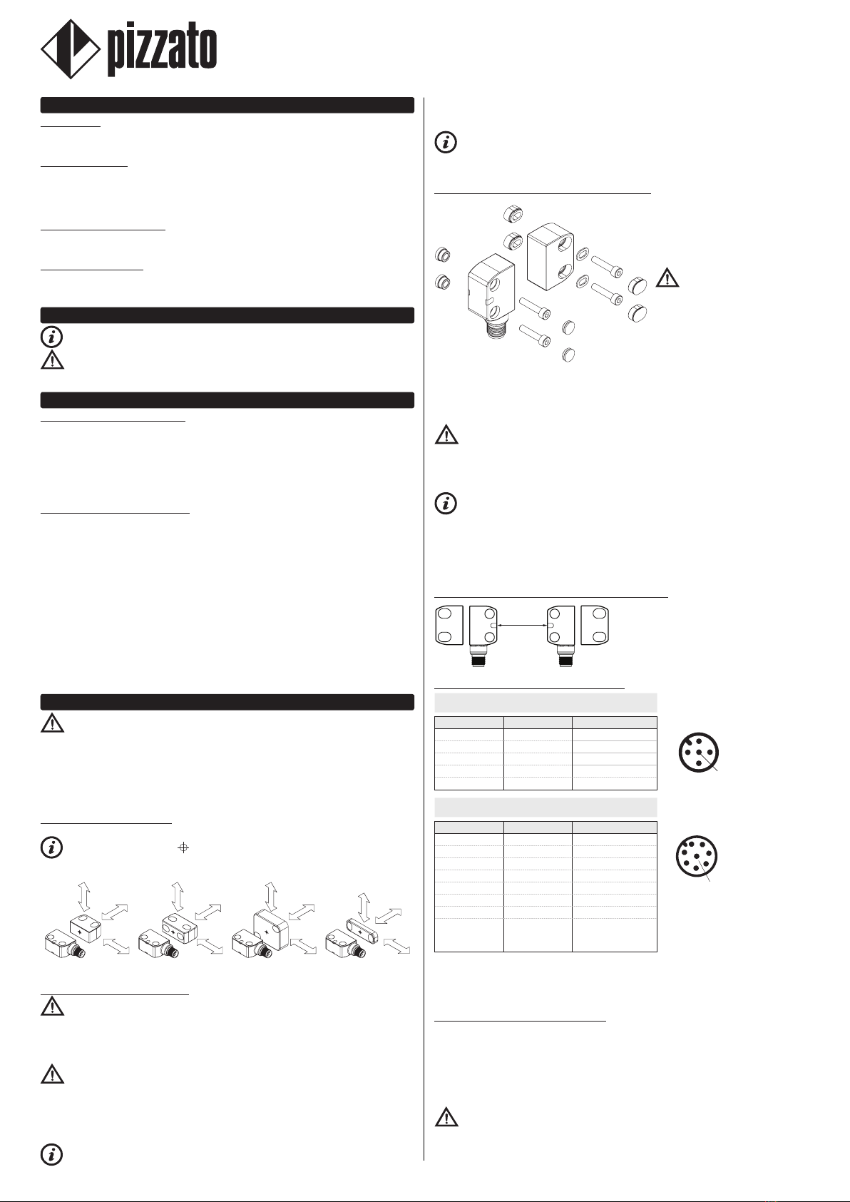
5.10 Replacement of the actuator (for articles ST G•4••••, ST G•8•••• only)
Attention: The machine manufacturer must restrict access to the sensor pro-
gramming mode to authorised personnel only.
Via input I3 it is possible to replace the coded actuator with a second actuator at any
time. This operation is repeatable an unlimited number of times. After programming
has been completed, the sensor will recognise only the actuator code corresponding
to the last executed programming operation.
1) Power the sensor at the rated voltage. The sensor carries out internal tests. The
LED illuminates as described in paragraph OPERATING STATES.
2) Activate the I3 programming input, by supplying with voltage Ue1 (see paragraph
TECHNICAL DATA). The LED illuminates purple to indicate it is ready to receive the
new code to be stored.
3) Move the new actuator towards the sensor, with the centring symbols aligned. The
LED flashes green twice, once programming has completed successfully.
4) Disable the I3 programming input: the sensor restarts automatically and repeats the
internal tests to switch to the RUN operating state.
The second actuator must be suitably fixed to the guard as described in paragraph
INSTALLATION INSTRUCTIONS. Once the operation is carried out, check recognition
of the newly programmed actuator and perform the sequence of functional tests
specified in these operating instructions.
This operation must not be carried out as a repair or maintenance operation. If the
device ceases to function correctly, replace the entire device and not just the actuator.
The programming operation of the actuator can be carried out either with the
safety inputs deactivated or with the safety inputs activated.
6 INSTRUCTIONS FOR PROPER USE
6.1 Installation
Attention: Installation must be carried out by qualified staff only. The OS1
and OS2 safety outputs of the device must be connected to the safety circuit of
the machine. The signalling output O3 is not a safety output and may not be used
individually in a safety circuit to determine safe state of guard closed.
- Do not stress the device with bending and torsion.
- Do not modify the device for any reason.
- Do not exceed the tightening torques specified in the present operating instructions.
- The device carries out an operator protection function. Any inadequate installation
or tampering can cause serious injuries and even death, property damage, and
economic losses.
- These devices must not be bypassed, removed, turned or disabled in any other way.
- If the machine where the device is installed is used for a purpose other than that
specified, the device may not provide the operator with efficient protection.
- The safety category of the system (according to EN ISO 13849-1), including the safe-
ty device, also depends on the external components connected to it and their type.
- Before installation, make sure the device is not damaged in any part.
- Avoid excessive bending of connection cables in order to prevent any short circuits
or power failures.
- Do not paint or varnish the device.
- Do not drill the device.
- Do not use the device as a support or rest for other structures, such as raceways,
sliding guides or similar.
- Before commissioning, make sure that the entire machine (or system) complies with
all applicable standards and EMC directive requirements.
- The fitting surface of the device must always be smooth and clean.
- The documents necessary for a correct installation and maintenance are always
available in the following languages: English, French, German and Italian.
- Should the installer be unable to fully understand the documents, the product must
not be installed and the necessary assistance may be requested (see paragraph
SUPPORT).
- Before commissioning the machine, and periodically, check for correct switching of
the outputs and correct operation of the system comprising the device and associ-
ated safety circuit.
- In proximity of the device do not carry out arc welding, plasma welding, or any other
process that may generate electromagnetic fields of intensity higher than the limits
prescribed by the standards, even when the sensor is off.Where welding operations
are to be carried out in the proximity of a previously installed device, it must first be
moved away from the work area.
Always attach the following operating instructions to the manual of the machine in
which the device is installed.
- These operating instructions must be kept available for consultation at any time and
for the whole period of use of the device.
6.2 Do not use in the following environments
- In environments where the application causes collisions, impacts or strong vibrations
to the device.
- In environments containing explosive or inflammable gases or dusts.
- In environments where ice can form on the device.
- In environments containing strongly aggressive chemicals, where the products used
coming into contact with the device may impair its physical or functional integrity.
6.3 Mechanical stop
Attention: The door must always be provided with an independent end-limit
mechanical stop at limit of travel.
Do not use the device as mechanical stop for the door. The actuator must not strike
the sensor.
6.4 Maintenance and functional tests
Attention: Do not disassemble or try to repair the device. In case of any
malfunction or failure, replace the entire device.
Attention: In case of damages or wear it is necessary to change the whole
device including its actuator. Correct operation cannot be guaranteed when the device
is deformed or damaged.
- The installer is responsible for establishing the sequence of functional tests to which
the device is to be subjected before the machine is started up and during maintenance
intervals.
- The sequence of the functional tests can vary depending on the machine complexity
and circuit diagram, therefore the functional test sequence detailed below is to be
considered as minimal and not exhaustive.
- Perform the following sequence of checks before the machine is commissioned and
at least once a year (or after a prolonged shutdown):
1) Open the guard while the machine is moving. The machine must stop immediately.
The stopping time of the machine must be always shorter than the time required by the
operator for opening the guard and reaching the dangerous parts.
2) Try to start the machine while the guard is open. The machine must not start.
3) Check correct actuator to device alignment.
4) Check that no external parts are damaged. If damaged, replace the entire device.
5) The actuator must be securely locked to the door; make sure that none of the machine
operator’s tools can be used to disconnect the actuator from the door.
- The device has been created for applications in dangerous environments, therefore
it has a limited service life. Although still functioning, after 20 years from the date
of manufacture the device must be replaced completely. The date of manufacture is
placed next to the product code (see paragraph MARKINGS).
6.5 Wiring
Attention: Check that the supply voltage is correct before powering the device.
- Keep the charge within the values specified in the electrical operation categories.
- Only connect and disconnect the device when the power is off.
- Do not open the device for any reason.
- Discharge static electricity before handling the product by touching a metal mass
connected to earth. Any strong electrostatic discharge could damage the device.
- Power the safety switch and the other devices connected to it from a single SELV
source and in accordance with the applicable standards.
- Always connect the protection fuse (or equivalent device) in series with the power
supply for each device.
- During and after the installation do not pull the electrical cables connected to the
device.
- For devices with integrated cable, the free end of the cable (if it does not have a con-
nector) must be properly connected inside a protected housing. The cable must be
adequately protected from cuts, impacts, abrasion, etc.
6.6 Additional prescriptions for safety applications with operator protection
functions
Provided that all previous requirements for the devices are fulfilled, for installations
with operator protection function additional requirements must be observed.
- The utilization implies knowledge of and compliance with following stand-
ards: EN 60947-5-3, EN ISO 13849-1, EN 62061, EN 60204-1, EN ISO 14119,
EN ISO 12100.
6.7 Limits of use
- Use the device following the instructions, complying with its operation limits and the
standards in force.
- The devices have specific application limits (min. and max. ambient temperature,
mechanical endurance, IP protection degree, etc.) These limitations are met by the
device only if considered individually and not as combined with each other.
- The manufacturer’s liability is to be excluded in the following cases:
1) Use not conforming to the intended purpose;
2) Failure to adhere to these instructions or regulations in force;
3) Fitting operations not carried out by qualified and authorized personnel;
4) Omission of functional tests.
- For the cases listed below, before proceeding with the installation contact our techni-
cal assistance service (see paragraph SUPPORT):
a) In nuclear power stations, trains, airplanes, cars, incinerators, medical devices or
any application where the safety of two or more persons depend on the correct opera-
tion of the device;
b) cases not listed in these operating instructions.
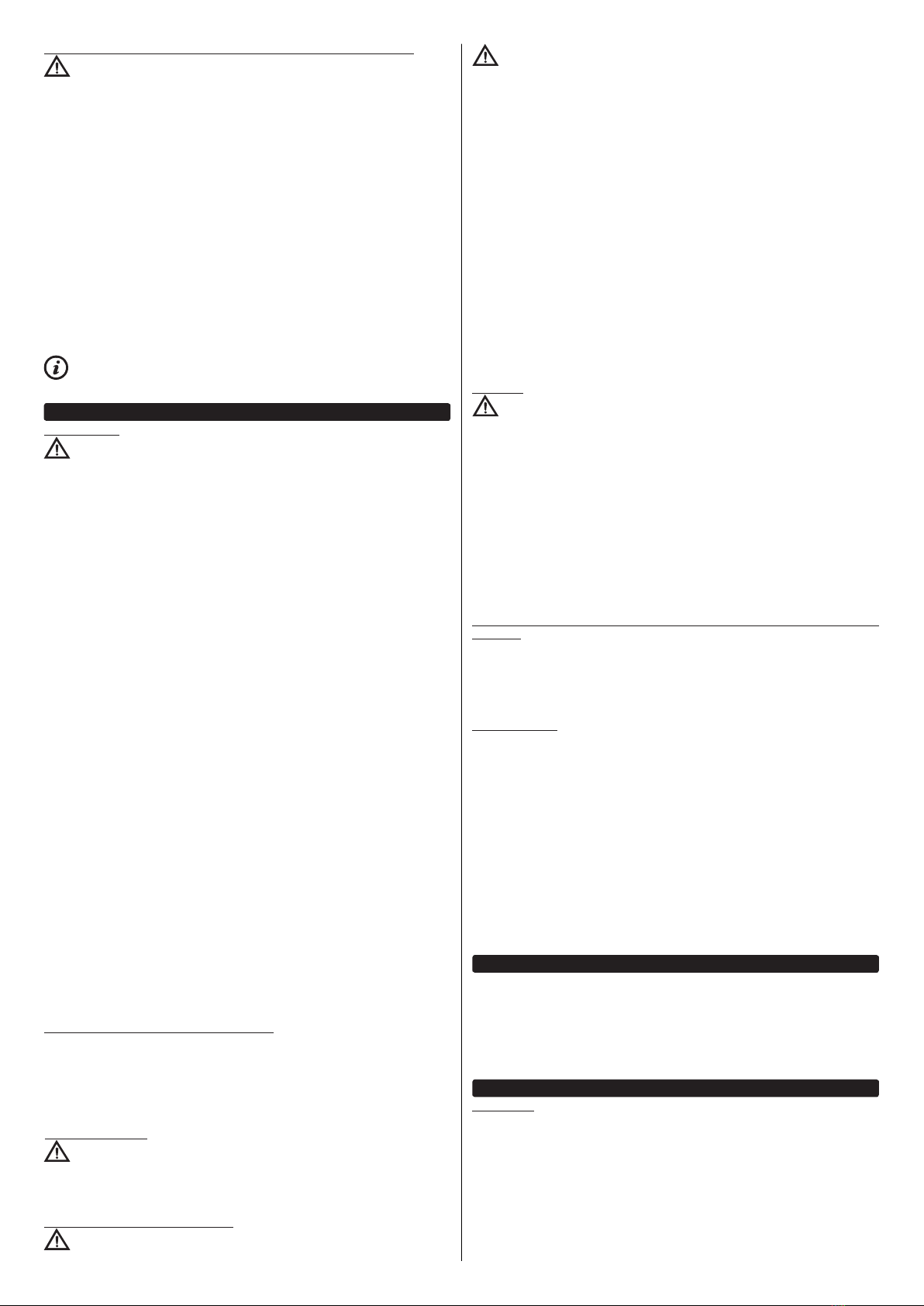
7 MARKINGS
The outside of the device is provided with external marking positioned in a visible
place. Marking includes:
- Producer trademark
- Product code
- Batch number and date of manufacture. Example: A19 ST1-123456. The batch's first
letter refers to the month of manufacture (A=January, B=February, etc.) The second
and third letters refer to the year of manufacture (19 = 2019, 20 = 2020, etc.)
8 TECHNICAL DATA
8.1 Housing
Housing made of glass fibre reinforced technopolymer, self-extinguishing.
Versions with integrated cable 5 x 0.25 mm2or 8 x 0.25 mm2, length 2 m, other lengths
on request.
Versions with M12 plastic or stainless steel connector.
Versions with 0.2 m cable length and integrated M12 connector, other lengths on
request.
Maximum length of connecting cables: 50 m.
(The cable length and section alter the deactivation impulses at the safety outputs. Check that the
capacity between the connecting cable's conductors is lower than that permitted in the electrical
data of the safety outputs)
Protection degree: IP67 acc. to EN 60529, IP69K acc. to ISO 20653
(Protect the cables from direct high-pressure and high-temperature jets)

10/20
8.2 General data
For safety applications up to: SIL 3 acc. to EN 62061
PL e, cat. 4 acc. to EN ISO 13849-1
Interlock, no contact, coded: type 4 acc. to EN ISO 14119
Level of coding acc. to EN ISO 14119: high with SM •1T actuators
low with SM •0T actuators
Safety parameters:
MTTFD: 1551 years
PFHD: 1,19E-09
DC: High
Mission time: 20 years
Operating temperature: -25 … +70 °C (articles ST G••••••)
-35 … +85 °C (articles ST G••••MK-T8)
Storage temperature: -35 … +85 °C
Vibration resistance: 10 gn (10...150 Hz) acc. to IEC 60068-2-6
Shock resistance: 30 gn; 11 ms acc. to EN 60068-2-27
Pollution degree 3
8.3 Power supply electrical data
8.3.1 Power supply electrical data
Rated operating voltage Ue: 24 Vdc
Supply voltage tolerance: ± 15% of Ue
Operating current at Uevoltage:
minimum: 20 mA
with all outputs at maximum power: 550 mA
Rated insulation voltage Ui: 32 Vdc
Rated impulse withstand voltage Uimp: 1.5 kV
External protection fuse: 1 A type Gg or equivalent device
Overvoltage category: III
8.3.2 Electrical data of IS1/IS2/I3/EDM inputs
Rated operating voltage Ue1: 24 Vdc
Rated current consumption: 2.5 mA
Switching time EDM state (tEDM): 500 ms
8.3.3 Electrical data of OS1/OS2 safety outputs
Rated operating voltage Ue2: 24 Vdc
Output type: PNP type OSSD
Maximum current per output Ie2: 0.2 A
Minimum current per output Im2: 0.5 mA
Thermal current Ith2: 0.2 A
Utilization category: DC13; Ue2=24 Vdc, Ie2=0.2 A
Short circuit detection: Yes
Overcurrent protection: Yes
Resettable internal protection fuse: 0.3 A
Duration of the deactivation impulses at the safety outputs: < 300 μs
Permissible capacitance between outputs: < 200 nF
Permissible capacitance between output and ground: < 200 nF
Response time (trI) after deactivation of inputs IS1 or IS2: < 15 ms
Response time (trA) after actuator removal: < 50 ms
Availability time: 2 s
8.3.4 Electrical data of O3 signalling output
Rated operating voltage Ue3: 24 Vdc
Output type: PNP
Maximum current per output Ie3: 0.1 A
Utilization category: DC13; Ue3=24 Vdc, Ie3=0.1 A
Short circuit detection: No
Overcurrent protection: Yes
Resettable internal protection fuse: 120 mA
8.3.5 Actuation data
SM G•T, SM D•T,
SM L•T actuators
SM E•T actuators
Assured operating distance Sao: 8 mm 14 mm
Assured release distance Sar: 20 mm 26 mm
Rated operating distance Sn: 11 mm 18 mm
Rated release distance Snr: 13 mm 20.5 mm
Repeat accuracy: ≤10 % sn
Differential travel: ≤20 % sn
RFID transponder frequency: 125 kHz
Max. switching frequency: 1 Hz
Minimum distance between two sensors: 50 mm
8.4 Compliance with standards
EN ISO 14119, IEC 61508-1, IEC 61508-2, IEC 61508-3, IEC 61508-4,
EN ISO 13849-1, EN ISO 13849-2, EN 62061, EN 60947-5-3, EN 60947-5-2,
EN 60947-1, EN 61326-1, EN 61326-3-1, EN 61326-3-2, EN IEC 63000,
ETSI EN 301 489-1, ETSI EN 301 489-3, ETSI 300 330-2, UL 508, CSA 22.2 No.14
8.5 Compliance with directives
Machinery Directive 2006/42/EC, EMC Directive 2014/30/EU, Radio Equipment
Directive 2014/53/EU, RoHS Directive 2011/65/EU, FCC Part 15
9 SPECIAL VERSIONS ON REQUEST
Special versions of the device are available on request.
The special versions may differ substantially from the indications in these operating
instructions.
The installer must ensure that he has received written information from the support
service regarding installation and use of the special version requested.
10 DISPOSAL
At the end of service life product must be disposed of properly, according to the
rules in force in the country in which the disposal takes place.
11 SUPPORT
The device has been created for safeguarding people’s physical safety, therefore in
case of any doubt concerning installation or operation methods, always contact our
technical support service:
Pizzato Elettrica Srl - Italy
Via Torino, 1 - 36063 Marostica (VI)
Telephone +39.0424.470.930
E-mail [email protected]
www.pizzato.com
Our support service provides assistance in Italian and English.
12 EC CONFORMITY DECLARATION
I, the undersigned, as a representative of the following manufacturer:
Pizzato Elettrica Srl - Via Torino, 1 - 36063 Marostica (VI) – ITALY
hereby declare that the product is in conformity with whatever prescribed by the 2006/42/
EC Machine Directive. The complete version of the present conformity declaration is
available on our website www.pizzato.com
Marco Pizzato
DISCLAIMER:
Subject to modifications without prior notice and errors excepted.The data given in this sheet
are accurately checked and refer to typical mass production values. The device descriptions
and its applications, the fields of application, the external control details, as well as information
on installation and operation, are provided to the best of our knowledge.This does not in any
way mean that the characteristics described may entail legal liabilities extending beyond the
“General Terms of Sale”, as stated in the Pizzato Elettrica general catalogue. Customers/
users are not absolved from the obligation to read and understand our information and
recommendations and pertinent technical standards, before using the products for their own
purposes. Taking into account the great variety of applications and possible connections of
the device, the examples and diagrams given in the present manual are to be considered as
merely descriptive; the user is deemed responsible for checking that the specific application
of the device complies with current standards. This document is a translation of the original
instructions. In case of discrepancy between the present sheet and the original copy, the
Italian version shall prevail. The present manual may not be reproduced, in whole or in part,
without the prior written permission by Pizzato Elettrica.
© 2019 Copyright Pizzato Elettrica. All rights reserved.

11/20
Pizzato Elettrica Srl
via Torino, 1
36063 MAROSTICA (VI)
ITALY
e-mail: [email protected]
web site: www.pizzato.com
Phone: +39.0424.470.930
ZE FOG131C19-EU
1 À PROPOS DU PRÉSENT DOCUMENT
1.1 Fonction
Le présent mode d'emploi fournit des informations sur l'installation, le raccordement
et l'utilisation sécurisée des articles suivants : ST G••••••.
1.2 Groupe cible
Les opérations décrites dans le présent mode d'emploi ne doivent être effectuées
que par un personnel qualifié, parfaitement capable de les comprendre et possédant
les qualifications techniques et professionnelles nécessaires pour travailler sur les
machines et les installations équipées des dispositifs de sécurité en question.
1.3 Champ d’application
Le présent mode d'emploi s'applique uniquement aux produits mentionnés au
paragraphe Fonction et à leurs accessoires
1.4 Instructions originales
La version italienne est la version originale des instructions du dispositif. Les versions
disponibles dans les autres langues sont une traduction des instructions originales.
2 PICTOGRAMMES UTILISÉS
Ce symbole indique des informations supplémentaires utiles.
Attention : Le non-respect de cette note de mise en garde peut provoquer une
rupture ou une défaillance pouvant compromettre la fonction de sécurité.
3 DESCRIPTION
3.1 Description du dispositif
Le dispositif de sécurité qui est décrit dans le présent mode d'emploi est défini
conformément à la norme EN ISO 14119 comme étant un interverrouillage sans
contact, codé du type 4.
Les capteurs de sécurité avec technologie RFID, dont il est question dans le présent
mode d'emploi, sont des dispositifs de sécurité conçus et réalisés pour le contrôle de
portails, protections, carters et protecteurs en général servant à protéger des parties
dangereuses de machines sans inertie.
3.2 Utilisation prévue du dispositif
- Le dispositif décrit dans le présent mode d'emploi est conçu pour être appliqué sur
des machines industrielles (comme définies dans la Directive Machines) en vue de
contrôler l'état de protections mobiles.
- La vente directe au public de ce dispositif est interdite. L'utilisation et l'installation
sont réservées à un personnel spécialisé.
- Il est interdit d'utiliser le dispositif à des fins autres que celles qui sont spécifiées
dans le présent mode d'emploi.
- Toute utilisation n'étant pas expressément envisagée dans le présent mode d'emploi
doit être considérée comme n'étant pas prévue par le fabricant.
- Par ailleurs, les utilisations suivantes ne sont pas conformes :
a) utilisation du dispositif ayant subi des modifications structurelles, techniques ou
électriques ;
b) utilisation du produit dans un domaine d'application autre que celui qui est décrit
dans le paragraphe CARACTÉRISTIQUES TECHNIQUES.
4 INSTRUCTIONS DE MONTAGE
Attention : L'installation d'un dispositif de protection ne suffit pas à garan-
tir la sécurité des opérateurs et le respect de normes ou de directives spécifiques
en matière de sécurité des machines. Avant d'installer un dispositif de protection, il
est nécessaire d'effectuer une analyse de risque spécifique, conformément aux exi-
gences essentielles de la Directive Machines en matière de sécurité et de santé.
Le fabricant ne garantit que la sécurité fonctionnelle du produit auquel se réfère le
présent mode d'emploi, et non la sécurité fonctionnelle de l'ensemble de la machine
ou de l'installation.
4.1 Directions d'actionnement
Le dispositif peut être utilisé en approchant l'actionneur depuis toutes les directions.
Les symboles de centrage apposés sur le dispositif et l'actionneur doivent
être face à face lorsque la protection est fermée, quel que soit le sens d'actionnement.
Art. ST G••••••-G•T Art. ST G••••••-D•T Art. ST G••••••-E•T Art. ST G••••••-L•T
4.2 Choix du type d'actionneur
Attention : Le dispositif est disponible avec deux types d'actionneur RFID : l'un
avec un haut niveau de codication (articles SM •1T) et l'autre avec un bas niveau de
codication (articles SM •0T). Si vous avez choisi un actionneur à bas niveau de codi-
fication, assurez-vous que les spécifications supplémentaires mentionnées au para-
graphe 7.2 de la norme EN ISO 14119:2013 sont bien respectées durant l'installation.
Attention : Si vous avez choisi un actionneur à bas niveau de codification, tout
autre actionneur de niveau de codification faible, éventuellement présent à l'endroit
où le dispositif a été installé, doit être isolé et étroitement surveillé, afin d'éviter tout
contournement du dispositif de sécurité. En cas d'installation de nouveaux action-
neurs de niveau de codification faible, les actionneurs d'origine à faible niveau de
codification doivent être éliminés ou rendus inutilisables.
Il est recommandé d'utiliser des actionneurs avec un haut niveau de codification
afin de rendre l'installation plus sûre et plus flexible. Ceci permet d'éviter de devoir
protéger le dispositif, l'adapter à des zones inaccessibles ou respecter d'autres spéci-
fications de la norme EN ISO 14119 pour les actionneurs à bas niveau de codification.
Le dispositif peut aussi être utilisé en combinaison avec les actionneurs SM D•T,
SM E•T et SM L•T avec un niveau de codication haut ou bas, le niveau de sécurité
restant le même.
4.3 Fixation du dispositif et de l'actionneur
Le capteur peut être fixé dans
n'importe quelle position. Le tour-
ner dans le sens le plus approprié
pour que la sortie des connexions
soit orientée dans le sens requis
par l'application particulière.
Attention : Après avoir défini
le sens de fixation du capteur,
insérer les douilles fournies dans
les trous situés du côté opposé à
l'entrée de la vis.
Le capteur et l'actionneur doivent
toujours être fixés avec 2 vis M4 de
classe de résistance 4.6 ou supé-
rieure et avec une sous-tête plate. Les vis doivent être montées avec du frein filet à
résistance moyenne et avoir un nombre de filets en prise égal ou supérieur à leur dia-
mètre. Il est interdit de fixer le dispositif ou l'actionneur avec un nombre de vis inférieur
à 2. Le couple de serrage des vis M4 compris entre 0,8 et 1,0 Nm.
Attention : Conformément à la norme EN ISO 14119, l'actionneur doit être fixé
au châssis de la porte de façon inamovible.
Pour une fixation correcte, il est également possible d'avoir recours à d'autres moyens,
tels que des rivets, des vis de sécurité inamovibles (one-way) ou tout autre système
de fixation équivalent, pourvu qu'il soit capable d'assurer une fixation adéquate.
Le dispositif est livré avec des bouchons de sécurité anti-manipulation. L’utili-
sation de bouchons est considérée comme une mesure appropriée pour réduire le
plus possible la possibilité d’un démontage de l’actionneur, selon EN ISO 14119. Par
conséquent, si les bouchons fournis sont fixés à l'appareil, des vis normales peuvent
être utilisées pour fixer l'actionneur.
Pour les réglages, ne pas utiliser de marteau ; dévisser les vis, régler manuellement
le dispositif, puis le serrer en position.
4.4 Montage de plusieurs systèmes capteur - actionneur
50 mm
Si plus d'un dispositif de sécurité est installé
sur la même machine, la distance de mon-
tage entre les systèmes capteur/actionneur
doit être d'au moins 50 mm.
4.5 Raccordements électriques du dispositif
Versions à 5 pôles
ST G•2••••, ST G•6••••
Connecteur M12 Câble Connexion 1
42
35
1 marron A1 (+)
2 blanc OS1
3 bleu A2 (-)
4 noir OS2
5gris O3 (a)
Versions à 8 pôles
ST G•3••••, ST G•4••••, ST G•5••••, ST G•7••••, ST G•8••••
Connecteur M12 Câble Connexion 1
2
345
6
7
8
Notes
a) sortie inversée pour les articles ST G•6••••,
ST G•7••••, ST G•8••••.
(b) pour les articles ST G•3••••, ST G•7••••.
(c) pour les articles ST G•4••••, ST G•8••••.
(d) pour les articles ST G•5••••.
1 blanc A1 (+)
2 marron IS1
3vert A2 (-)
4 jaune OS1
5gris O3 (a)
6 rose IS2
7 bleu OS2
8 rouge
non relié (b)
I3 (c)
EDM (d)
Légende :
A1-A2 = alimentation I3 = entrée de programmation
IS1-IS2 = entrées de sécurité O3 = sortie de signalisation
OS1-OS2 = sorties de sécurité EDM = entrée de surveillance contacteurs extérieurs
4.6 Points d'intervention du capteur RFID
En plaçant l'actionneur à l'intérieur de la zone de sécurité d'actionnement (zone en
gris foncé), le capteur active les sorties de sécurité (LED allumée en vert).
À la sortie de l'actionneur de la zone de sécurité, le capteur maintient les sorties de
sécurité activées et, en faisant clignoter la LED de couleur jaune, il signale l'entrée de
l'actionneur dans la zone limite d'actionnement (zone gris clair).
À la sortie de l'actionneur de la zone limite d'actionnement, le capteur désactive les
sorties (LED allumée en jaune).
Attention : Les distances d'actionnement/relâchement du dispositif peuvent être

12/20
influencées par la présence d'un matériau conducteur ou magnétique à proximité du
capteur. Les distances utiles d'actionnement et de relâchement doivent toujours être
vérifiées après le montage.
Zones d’activation pour les actionneurs SM G•T, SM D•T, SM L•T
25
20
15
10
5
25
20
15
10
5
0 5-5 10-10-15-20 15 20 0 5-5 10-10-15-20 15 20
(mm) (mm)
(mm)(mm)
Zones d’activation pour les actionneurs SM E•T
(mm)
(mm)(mm)
30
25
20
15
10
5
30
25
20
15
10
5
(mm)
0 5-5 10-10-15-20 15 20 0 5-5 10-10-15-20 15 20
Légende :
Distance de déclenchement nominale sn(mm)
Distance de relâchement nominale snr (mm)
Note : L'évolution des zones d’activation est donnée à titre purement indicatif, une
éventuelle application sur des surfaces métalliques peut réduire les distances d'inter-
vention.
5 FONCTIONNEMENT
5.1 Définitions
États du capteur :
- OFF : le capteur est éteint, hors tension.
- POWER ON : état suivant immédiatement la mise en marche, lorsque le capteur effectue
des tests internes.
- RUN : état dans lequel le capteur fonctionne normalement.
- ERROR : état de sécurité dans lequel les sorties de sécurité sont désactivées. Il
indique la présence d'une défaillance à l'intérieur ou à l'extérieur du dispositif, telle
que :
- un court-circuit entre les sorties de sécurité (OS1 et OS2) ;
- un court-circuit entre une sortie de sécurité et la terre ou ;
- un court-circuit entre une sortie de sécurité et la tension d'alimentation ;
Pour sortir de cet état, il faut redémarrer le capteur.
- La fonction EDM (External Device Monitoring), si elle est présente, permet au dis-
positif de surveiller l'état des contacteurs extérieurs. L'activation/désactivation des
contacteurs extérieurs doit suivre les sorties de sécurité du capteur ST dans un temps
prédéfini (voir paragraphe CARACTÉRISTIQUES TECHNIQUES).
5.2 Description du fonctionnement générale
f2
f1 f3
f0
OS1
OS2
IS2
IS1
O3
A2A1 LED
RGB
I3 /
EDM f4
LED
CONTROLLER
Une fois que le capteur a été correctement
installé en suivant les présentes instruc-
tions, il peut être mis sous tension. Le sché-
ma présente les fonctions logiques qui inte-
ragissent à l'intérieur du capteur.
Dans l'état initial POWER ON, la fonction f0
du capteur effectue un autodiagnostic in-
terne qui, en cas de succès, fait passer le
dispositif à l'état RUN. Si le test n'est pas
réussi, le capteur passe à l'état ERROR.
L'état RUN indique un fonctionnement nor-
mal : la fonction f2 contrôle la présence de
l'actionneur dans la zone d'activation de
sécurité.
La fonction f3 active les sorties de sécurité
OS1 et OS2 selon la version du capteur :
- dans les versions sans entrées de sécurité
IS1 et IS2 (ST G•2••••, ST G•6••••), la pré-
sence de l'actionneur suffit ;
- dans les versions avec entrées de sécurité IS1 et IS2 (ST G•3••••, ST G•4••••, ST G•7••••,
ST G•8••••), la présence de l'actionneur et l'activation des entrées IS1 et IS2 sont véri-
fiées ;
- dans les versions avec EDM (ST G•5••••), la présence de l'actionneur, l'activation
des entrées IS1 et IS2 et la présence du signal de rétroaction des contacteurs ex-
ternes sont vérifiées.
Pendant l'état RUN, la fonction f0 effectue des tests internes cycliques afin de mettre
en évidence les éventuels défauts. La détection d'une erreur interne fait passer le
capteur à l'état ERROR (la LED s'allume en rouge, fixe ou clignotant selon le type
de l'erreur), ce qui provoque la désactivation immédiate des sorties de sécurité par
la fonction f3. L'état ERROR peut apparaître même dans le cas de courts-circuits
entre les sorties de sécurité (OS1 et OS2) ou d'un court-circuit d'une sortie vers la
masse ou vers la tension d'alimentation. Dans ce cas aussi, la fonction f3 désactive
les sorties de sécurité et l'état d'erreur est indiqué par une séquence de clignotement
correspondante de la LED.
La sortie de signalisation O3, selon la version choisie, s'active ou se désactive pen-
dant l'état RUN lorsque l'actionneur est détecté à l'intérieur de la zone d'activation,
indépendamment de l'état des éventuelles entrées IS1 et IS2.
La fonction f4 surveille l'état d'activation de l'entrée I3 (versions ST G•4•••• et
ST G•8••••) ou EDM (versions ST G•5••••):
- Pour les versions avec entrée I3 pour la programmation de l’actionneur, quand l'en-
trée est active et que le dispositif est dans l'état RUN, la fonction f4 active l'état de
programmation de l'actionneur (voir paragraphe REMPLACEMENT DE L'ACTION-
NEUR) ;
- Pour les versions avec entrée EDM, la fonction f4 contrôle la cohérence du signal
EDM pendant les changements d'état et quand les sorties de sécurité sont inactives
(voir paragraphe DESCRIPTION DU FONCTIONNEMENT DES VERSIONS AVEC
ENTRÉE EDM).
Les informations résultant des états des fonctions f0, f1, f2, f3, f4 sont traitées et
signalées à l'utilisateur via des séquences d'allumage et des changements de couleur
des LED RVB externes du dispositif comme décrit au paragraphe ÉTATS DE FONC-
TIONNEMENT.
5.3 Description du fonctionnement des versions avec entrées de sécurité IS1 et
IS2 (articles ST G•3••••, ST G•4••••, ST G•5••••, ST G•7••••, ST G•8••••)
La fonction f1 évalue l'état des entrées IS1 et IS2.
L'état, mais aussi la cohérence des entrées IS1 et IS2 sont surveillés : généralement,
les entrées sont actionnées simultanément. En cas de désactivation d'une seule des
deux entrées, le capteur désactive les sorties de sécurité et signale un état d'inco-
hérence des entrées au moyen de la séquence de clignotement correspondante de
la LED (voir paragraphe ÉTATS DE FONCTIONNEMENT).Les deux entrées doivent
être désactivées, puis réactivées, pour que les sorties de sécurité puissent redevenir
actives.
5.4 Description du fonctionnement des versions avec entrée EDM (articles
ST G•5••••)
La fonction f4 permet d'effectuer le contrôle des contacts NC forcés des contacteurs
ou relais qui sont commandés par les sorties de sécurité du capteur proprement dit ;
ce contrôle est effectué par le capteur en surveillant l'entrée EDM (External Device
Monitoring). Avec les entrées de sécurité actives et l'actionneur dans la zone d'activa-
tion, les sorties de sécurité s'activent uniquement lorsque l'entrée EDM est active. Au
moment de l'activation des sorties de sécurité, le dispositif vérifie que l'entrée EDM se
désactive dans le temps tEDM. Au moment de la désactivation des sorties de sécurité,
le dispositif vérifie que le signal EDM se réactive dans le temps tEDM.
En cas de dépassement du temps maximum tEDM, le système passe à un état d'erreur
ERROR et désactive les sorties de sécurité (si elles sont actives), tout en signalant
l'erreur au moyen de la séquence de clignotement correspondante de la LED (voir
paragraphe ÉTATS DE FONCTIONNEMENT).
5.5 Connexion en série avec des modules de sécurité
En cas d'utilisation d'un capteur sans entrée EDM, les sorties de sécurité OS1 et OS2
doivent être connectées à un module de sécurité ou à un API de sécurité.
Le dispositif est également équipé d'une sortie de signalisation O3 qui est activée
(articles ST G•2••••, ST G•3••••, ST G•4••••) ou désactivée (articles ST G•6••••,
ST G•7••••, ST G•8••••) quand le protecteur respectif est fermé. Cette information
peut être gérée par un automate selon les besoins spécifiques du système réalisé ou
par un module de sécurité programmable de la série CS MP de Pizzato Elettrica qui
permet de gérer des sorties de sécurité et de signalisation.
Exemple de connexion
avec un module de sécurité et un API
Exemple de connexion
avec un module de sécurité programmable
ST •••••••
ST •••••••
ST •••••••
PLC
O3
O3
O3
+ Vcc
Ixx Ixx
OS1 OS2
IS1 IS2
IS1 IS2
IS1 IS2
OS1 OS2
OS1 OS2
SM ••TSM ••TSM ••T
ST •••••••
ST •••••••
ST •••••••
O3
O3
O3
+ Vcc
Ixx Ixx
OS1 OS2
IS1 IS2
IS1 IS2
IS1 IS2
OS1 OS2
OS1 OS2
SM ••TSM ••TSM ••T
Il est possible d'installer jusqu'à 32 dispositifs connectés en cascade, tout en main-
tenant la catégorie de sécurité 4 / PL e selon la norme EN ISO 13849-1 et le niveau
d'intégrité SIL CL 3 selon la norme EN 62061.
Vérifier que les valeurs PFH et MTTFd du système, formé par les dispositifs en cas-
cade et l'ensemble du circuit de sécurité, satisfont bien aux exigences du niveau SIL/
PL requis par l'application.
Pour cette méthode de connexion, respectez les indications suivantes.
- Connecter les entrées du premier dispositif de la chaîne à la tension d'alimentation.
- Les sorties de sécurité OS1 et OS2 du dernier dispositif de la chaîne doivent être
reliées au circuit de sécurité de la machine.
- Si un module de sécurité est utilisé, vérifier que les caractéristiques des sorties de
sécurité OS1/OS2 sont compatibles avec les entrées du module de sécurité (voir
paragraphe INTERFAÇAGE).
- Respecter les limites de capacité parasite des lignes de sortie qui sont spécifiées
dans les caractéristiques électriques (voir paragraphe CARACTÉRISTIQUES
TECHNIQUES).
- Assurez-vous que le temps de réponse de la cascade correspond aux exigences de
la fonction de sécurité recherchée.
- Le temps de réponse de la chaîne doit être calculé en tenant compte du temps de
réponse de chaque dispositif.
Le nombre maximal de 32 dispositifs connectés en cascade dépend également
de la longueur et de la section des conducteurs utilisés entre les dispositifs. Notre
service de support technique peut vous aider à calculer les distances maximales et
les sections minimales des conducteurs à utiliser pour le bon fonctionnement des
dispositifs connectés en cascade (voir paragraphe SUPPORT).
Module de sécurité
Pizzato Elettrica
série CS
Module de sécurité programmable
Pizzato Elettrica
série CS MP

13/20
5.6 Connexion EDM (External Device Monitoring)
ST G•51•••
ST G•310••
ST G•310••
PLC
IS1
K1 K2
O3
SM ••TSM ••TSM ••T
O3
O3
EDM
+
+
IS2
OS1 OS2
IS1 IS2
IS1 IS2
OS1 OS2
OS1 OS2
Pour certaines applications spéci-
fiques, au lieu de la connexion avec des
modules de sécurité, il est possible
d'utiliser l'article ST G•51••• avec le
contrôle des contacts NC forcés des
relais (K1, K2) connectés à l'entrée
EDM, en tant que dernier capteur de la
chaîne.
5.7 Interfaçage
Connexions aux modules de sécurité CS AR-08••••
Configuration des entrées avec démarrage contrôlé
2 canaux / catégorie 4 / jusqu'à SIL 3 / PL e
Versions à 5 pôles Versions à 8 pôles
S33
S21 S22 S35 S34 A2
S52
S12
A1
-
+
OS2
A1
+
A2
-
ST
CS
OS1
S33
S21 S22 S35 S34 A2
S52
S12
A1
-
+
OS2
OS1
IS2
IS1
A1
+
A2
-
ST
CS
Connexions aux modules de sécurité CS AR-05•••• / CS AR-06••••
Conguration des entrées avec démarrage manuel (CS AR-05••••) ou démarrage contrôlé (CS
AR-06••••)
2 canaux / catégorie 4 / jusqu'à SIL 3 / PL e
Versions à 5 pôles Versions à 8 pôles
S21 S22 S34 A2
A1
-
+
S52
S12
OS2
OS1
A1
+
A2
-
ST
CS
S21 S22 S34 A2
A1
-
+
S52
S12
OS2
OS1
IS2
IS1
A1
+
ST
CS
A2
-
Connexions aux modules de sécurité CS AT-0••••• / CS AT-1•••••
Configuration des entrées avec démarrage contrôlé
2 canaux / catégorie 4 / jusqu'à SIL 3 / PL e
Versions à 5 pôles Versions à 8 pôles
S33
S21 S22 S35 S34 A2
A1
-
+
S31
S12
OS2
OS1
A1
+
A2
-
ST
CS
S33
S21 S22 S35 S34 A2
A1
-
+
S31
S12
OS2
OS1
IS2
IS1
A1
+
A2
-
ST
CS
Connexions aux modules de sécurité CS MF••••0, CS MP••••0
Les branchements varient en fonction du programme du module
Catégorie 4/ jusqu'à SIL 3 / PL e
Versions à 5 pôles Versions à 8 pôles
Ixx
Ixx
OS2
OS1
A1
+
OS2
OS1
A1
+
Ixx
Ixx
A2
-
A2
-
ST ST
CS
Ixx
Ixx
OS2
OS1
IS2
IS1
A1
+
OS2
OS1
IS2
IS1
A1
+
Ixx
Ixx
A2
-
A2
-
ST ST
CS
Raccordements avec des contacteurs extérieurs (versions avec EDM uniquement)
K1
K2
-
-
+
A1 IS1
OS1 OS2
IS2 A2
+
-
ST G•51••• EDM
Les articles ST G•5•••• doivent être reliés
à des contacteurs avec contacts forcés
de sortie, conformément au schéma ci-
contre. Le capteur ainsi relié peut être
classé comme dispositif pour circuit de
commande jusqu'à PDF-M (EN 60947-
5-3)
Remarque : si un contacteur de
sécurité est directement relié aux sorties
de sécurité OS, il est nécessaire d'utili-
ser des diodes de commutation rapide,
connectées en parallèle aux bobines des
contacteurs en question.
Connexions à des modules d'extension Pizzato Elettrica (ex. CS ME-03••••)
(seulement versions ST G•5••••)
OS2
+
-
ST G•51•••
EDM
A2
A1
A2
IS2
IS1
OS1
OS2
OS1
EDMEDM
5.8 États de fonctionnement
Une LED de signalisation multicolore sur le capteur indique,
au moyen de séquences de clignotement et de changements
de couleurs, les différents états de fonctionnement du dispo-
sitif ainsi que les avertissements et les erreurs éventuels
concernant les composants électroniques interne.
La LED est visible des deux côtés du capteur, quel que soit
le sens de montage du dispositif.
Les états de fonctionnement prédéfinis du capteur (OFF, RUN, ERROR, SET) sont
indiqués par la lumière fixe de la LED.
Séquence de clignotement de la LED État du
capteur Description
OFF Capteur éteint.
GN
RUN État de fonctionnement normal avec sorties de
sécurité activées. Il n'y a ni erreur ni avertissement.
YE
RUN État de fonctionnement normal avec sorties de
sécurité désactivées. Il n'y a ni erreur ni avertisse-
ment.
VT
SET État d'acquisition d'un nouvel actionneur.
RD
ERROR État d'erreur interne du dispositif.
Tableau 1 : États de fonctionnement prédéfinis
Si un événement de type ERROR se produit, la LED alterne cycliquement entre une
lumière fixe pour l'état ERROR (voir tableau 1) et une des séquences de clignotement
indiquées dans le tableau 2 correspondant aux différents états d'erreur.
Séquence de clignotement de la LED État du
capteur Description Prio-
rité
RD RD RD
ERROR Erreur de température : la température du
capteur est en dehors des limites admissi-
bles.
9
RD RD RD RD
ERROR Erreur de tension : la tension d'alimentation
du capteur est en dehors des limites admis-
sibles.
8
RD RD YE RD
ERROR Court-circuit entre les sorties de sécurité
OS1 et OS2. 7
Tableau 2 : Messages de type ERROR
Si un événement de type WARNING se produit, la LED alterne cycliquement entre
la lumière fixe de l'état de fonctionnement actuel (voir tableau 1) et la séquence de
clignotement correspondante indiquée dans le tableau 3.
Séquence de clignotement de la LED État du
capteur Description Prio-
rité
RD
WARNING Avertissement de température : la tempéra-
ture du capteur est proche des limites ad-
missibles.
6
RD RD
WARNING Erreur de tension : la tension d'alimentation
est proche des limites admissibles. 5
YE YE
WARNING Pas de signal aux entrées IS1 et IS2. 4
YE GN
WARNING Entrées IS1 et IS2 non cohérentes. 3
YE
WARNING L'actionneur se trouve dans la zone limite de
détection. 2
Tableau 3 : Messages de type WARNING
Légende : GN = vert RD = rouge YE = jaune
BU = bleu VT = violet
Les événements de type WARNING sont généralement réversibles. Les
événements de type ERROR ne sont pas réversibles : le dispositif reste dans l'état
d'erreur, il doit être arrêté et la cause de l'erreur doit être résolue avant de le remettre
en service.
S'il y a plusieurs événements de type ERROR ou WARNING en même temps,
seule celui de priorité la plus élevée est affichée. Par exemple, en cas d'avertissement
de température et de tension, seule la séquence d'avertissement de la température
est affichée ; la séquence d'avertissement de la tension n'apparaît que lorsque la
séquence d'avertissement de la température cesse d'être active, c'est-à-dire lorsque
la température dépasse le seuil d'alarme.
Module d'extension
Pizzato Elettrica
CS ME-03••••

14/20
5.9 Entrée de réarmement
L'entrée I3 permet de réinitialiser les états d'erreur suivants, dus à une défaillance à
l'extérieur du dispositif :
- un court-circuit ou une charge excessive des sorties de sécurité (OS1 et OS2),
- un court-circuit entre une sortie de sécurité et la tension d'alimentation.
5.10 Remplacement de l'actionneur (uniquement pour les articles ST G•4••••,
ST G•8••••)
Attention : Le fabricant de la machine doit faire en sorte que l'accès au mode de
programmation du capteur soit permis uniquement au personnel autorisé.
L'entrée I3 peut être utilisée à tout moment pour remplacer l'actionneur codé par un
deuxième actionneur. Cette opération peut être répétée un nombre illimité de fois.
Lorsque la programmation a été effectuée, le capteur reconnaît seulement le code de
l'actionneur correspondant à la dernière programmation effectuée.
1) Mettez le capteur sous tension nominale. Le capteur effectue des tests internes. La
LED s'allume comme décrit au paragraphe ÉTATS DE FONCTIONNEMENT.
2) Appliquez la tension Ue1 pour activer l'entrée de programmation I3 (voir paragraphe
CARACTÉRISTIQUES TECHNIQUES). La LED s'allume en violet pour indiquer
l'attente du nouveau code à mémoriser.
3) Approchez le nouvel actionneur du capteur en alignant les symboles de centrage.
La LED clignote deux fois en vert si la programmation est réussie.
4) Désactivez l'entrée de programmation I3 : le capteur redémarre automatiquement et
effectue de nouveau les tests internes pour ensuite passer à l'état de fonctionnement
RUN.
Le deuxième actionneur doit être fixé de manière adéquate à la protection, comme
expliqué au paragraphe INSTRUCTIONS DE MONTAGE. Une fois l'opération
effectuée, contrôlez la reconnaissance du nouvel actionneur programmé et effectuer
la séquence de tests fonctionnels prévues dans le présent mode d'emploi.
Cette opération ne doit pas être réalisée comme une opération de réparation ou
d'entretien. Si le dispositif cesse de fonctionner correctement, remplacer le dispositif
entier et pas uniquement l'actionneur.
L'opération de programmation de l'actionneur peut s'effectuer aussi bien avec
les entrées de sécurité inactives qu'avec les entrées de sécurité actives.
6 MISES EN GARDE POUR UNE UTILISATION CORRECTE
6.1 Installation
Attention : L’installation doit être effectuée exclusivement par du personnel
qualifié. Les sorties de sécurité OS1 et OS2 du dispositif doivent être reliées au
circuit de sécurité de la machine. La sortie de signalisation O3 n'est pas une sortie de
sécurité et ne peut pas être utilisée individuellement au sein d'un circuit de sécurité
pour déterminer l'état de sécurité d'un protecteur fermé.
- Ne pas soumettre le dispositif à des contraintes de flexion ou de torsion.
- Ne pas modifier en aucun cas le dispositif.
- Ne pas dépasser les couples de serrage indiqués dans le présent mode d'emploi.
- Le dispositif sert à protéger les opérateurs. Une mauvaise installation ou une mani-
pulation intempestive peuvent causer de graves blessures, voire la mort, des dom-
mages matériels et des pertes économiques.
- Ces dispositifs ne doivent pas être contournés, enlevés, tournés ni désactivés par
d'autres moyens.
- Si la machine, munie de ce dispositif, est utilisée à des fins autres que celles qui
sont spécifiées, le dispositif pourrait ne pas protéger l'opérateur de manière efficace.
- La catégorie de sécurité du système (selon EN ISO 13849-1) comprenant le dis-
positif de sécurité dépend aussi des composants extérieurs qui y sont reliés et de
leur typologie.
- Avant l'installation, s'assurer que le dispositif est totalement intact.
- S'abstenir de plier les câbles de connexion de manière excessive afin d'éviter les
courts-circuits et les coupures.
- Ne pas vernir ni peindre le dispositif.
- Ne pas percer le dispositif.
- Ne pas utiliser le dispositif comme support ou appui pour d'autres structures (che-
mins, guides de glissement ou autres).
- Avant la mise en service, veiller à ce que l'ensemble de la machine, ou le système,
soient bien conformes aux normes applicables et aux exigences de la directive sur
la compatibilité électromagnétique.
- La surface de montage du dispositif doit toujours être propre et plane.
- La documentation requise pour une installation et un entretien corrects est toujours
disponible dans les langues suivantes : anglais, français, allemand, italien.
- Si l'installateur n'est pas en mesure de comprendre pleinement la documentation,
il ne doit pas procéder à l'installation du produit et peut demander de l'aide (voir
paragraphe SUPPORT).
- Vérifier périodiquement, et aussi lors de la première mise en marche, la bonne com-
mutation des sorties et le bon fonctionnement du système composé du dispositif et
du circuit de sécurité associé.
- À proximité du dispositif, même éteint, n'effectuez aucun soudage à l'arc, au plasma,
ni aucun autre procédé pouvant générer des champs électromagnétiques d'une
intensité supérieure aux limites prescrites par les normes. En cas d'opérations de
soudage à réaliser à proximité d'un dispositif installé précédemment, veiller d'abord
à éloigner celui-ci de la zone de travail.
- Toujours joindre le présent mode d'emploi au manuel de la machine sur laquelle le
dispositif est installé.
- La conservation des présentes prescriptions d’utilisation doit permettre de les
consulter sur toute la durée d'utilisation du dispositif.
6.2 Ne pas utiliser dans les environnements suivants
- Environnement dans lequel l'application comporte des vibrations et des chocs im-
portants pour le dispositif.
- Environnement exposé à des poussières ou gaz explosifs ou inflammables.
- Dans des espaces où des manchons de glace peuvent se former sur le dispositif.
- Environnement contenant des substances chimiques fortement agressives et dans
lequel les produits entrant en contact avec le dispositif risquent de compromettre
son intégrité physique et fonctionnelle.
6.3 Arrêt mécanique
Attention : La porte doit toujours être équipée d'un arrêt mécanique indépendant,
au bout de sa course de fermeture.
Ne pas utiliser le dispositif comme arrêt mécanique de la porte. L’actionneur ne doit
pas heurter le capteur.
6.4 Entretien et essais fonctionnels
Attention : Ne pas démonter ni tenter de réparer le dispositif. En cas de
défaillance ou de panne, remplacer le dispositif tout entier.
Attention : En cas d’endommagement ou d’usure, il faut remplacer tout le
dispositif, compris l’actionneur. Le fonctionnement n'est pas garanti en cas de
dispositif déformé ou endommagé.
- L'installateur est tenu de déterminer une séquence de tests fonctionnels à laquelle
soumettre le dispositif, avant la mise en service de la machine et pendant les
intervalles d'entretien.
- La séquence des tests fonctionnels peut varier en fonction de la complexité de la
machine et de son schéma de circuit ; la séquence de tests fonctionnels indiquée ci-
après doit donc être considérée comme étant minimum et non exhaustive.
- Avant de mettre la machine en service et au moins une fois par an (ou après un arrêt
prolongé), effectuer la séquence de tests suivante :
1) Ouvrir la protection avec la machine en mouvement. La machine doit s'arrêter
immédiatement. Le temps d'arrêt de la machine doit toujours être inférieur au temps
que l'opérateur met à ouvrir la protection et à atteindre les éléments dangereux.
2) Avec la protection ouverte, essayer de mettre la machine en marche. La machine
ne doit pas démarrer.
3) Vérifier l'alignement correct entre l'actionneur et le dispositif.
4) Vérifier que toutes les pièces externes ne sont pas endommagées. Si vous
constatez des dommages, remplacez complètement le dispositif.
5) L'actionneur doit être solidement fixé à la porte ; s'assurer qu'aucun des outils utilisés
par l'opérateur de la machine n'est en mesure de détacher l'actionneur de la porte.
- Le dispositif a été conçu pour des applications dans des environnements dangereux,
son utilisation est donc limitée dans le temps. 20 ans après la date de fabrication,
il faut entièrement remplacer le dispositif, même s'il marche encore. La date de
fabrication est indiquée à côté du code du produit (voir paragraphe MARQUAGES).
6.5 Câblage
Attention : Vérifier que la tension d'alimentation est correcte avant de brancher
le dispositif.
- Maintenir la charge dans les plages de valeurs électriques indiquées dans les caté-
gories d'emploi.
- Brancher et débrancher le dispositif uniquement lorsqu'il est hors tension.
- N'ouvrir le dispositif en aucun cas.
- Avant de manipuler le produit, décharger l'électricité statique en touchant une masse
métallique reliée à la terre. De fortes décharges électrostatiques risquent d'endom-
mager le dispositif.
- Alimenter l'interrupteur de sécurité et les autres dispositifs qui y sont reliés depuis
une source unique du type SELV et conforme aux normes pertinentes.
- Toujours brancher le fusible de protection (ou tout dispositif équivalent) en série sur
l'alimentation pour chaque dispositif.
- Durant et après l'installation, ne pas tirer sur les câbles électriques qui sont reliés
au dispositif.
- Pour les dispositifs avec câble intégré, l'extrémité libre du câble, si elle est dépourvue
de connecteur, doit être correctement raccordée à l'intérieur d'un boîtier protégé. Le
câble doit être opportunément protégé contre d'éventuels chocs, coupures, abra-
sions, etc.
6.6 Prescriptions supplémentaires pour les applications de sécurité ayant des
fonctions de protection des personnes
Toutes les prescriptions précédentes étant bien entendues, il faut également respec-
ter les prescriptions supplémentaires suivantes lorsque les dispositifs sont destinés à
la protection des personnes.
- L’utilisation implique le respect et la connaissance des normes EN 60947-5-3,
EN ISO 13849-1, EN 62061, EN 60204-1, EN ISO 14119, EN ISO 12100.
6.7 Limites d’utilisation
- Utiliser le dispositif selon les instructions, en observant ses limites de fonctionne-
ment et conformément aux normes de sécurité en vigueur.
- Les dispositifs ont des limites d'application spécifiques (température ambiante, mini-
male et maximale, durée de vie mécanique, degré de protection IP, etc.) Les dispo-
sitifs satisfont à ces limites uniquement lorsqu'ils sont considérés individuellement et
non combinés entre eux.
- La responsabilité du fabricant est exclue en cas de :
1) utilisation non conforme ;
2) non-respect des présentes instructions ou des réglementations en vigueur ;
3) montage réalisé par des personnes non spécialisées et non autorisées ;
4) Omission des tests fonctionnels.
- Dans les cas d'application énumérés ci-après, avant toute installation, contacter
l'assistance technique (voir paragraphe SUPPORT) :
a) dans les centrales nucléaires, les trains, les avions, les voitures, les incinérateurs,
les dispositifs médicaux ou toute autre application dans laquelle la sécurité de deux
personnes ou plus dépend du bon fonctionnement du dispositif ;
b) dans des cas non mentionnés dans le présent mode d'emploi.

15/20
7 MARQUAGES
Le dispositif présente un marquage, placé à l'extérieur de manière visible. Le mar-
quage comprend :
- Marque du fabricant
- Code du produit
- Numéro de lot et date de fabrication. Exemple : A19 ST1-123456. La première lettre
du lot indique le mois de fabrication (A = Janvier, B = Février, etc.) Les deuxième
et troisième chiffres indiquent l'année de fabrication (19 = 2019, 20 = 2020, etc.)
8 CARACTÉRISTIQUES TECHNIQUES
8.1 Boîtier
Boîtier en technopolymère renforcé à la fibre de verre, autoextinguible.
Versions avec câble intégré 5 x 0,25 mm2ou 8 x 0,25 mm2, longueur 2 m, autres
longueurs sur demande.
Versions avec connecteur M12 en plastique ou en acier inox.
Versions avec câble longueur 0,2 m et connecteur M12 intégré, autres longueurs sur
demande.
Longueur maximale des câbles de raccordement : 50 m.
(La longueur et la section du câble altèrent les impulsions de désactivation sur les sorties de
sécurité.Vérifier que la capacité entre les conducteurs du câble de raccordement est inférieure à la
capacité admissible qui est indiquée dans les caractéristiques électriques des sorties de sécurité)
Degré de protection : IP67 selon EN 60529 IP69K selon ISO 20653
(Protéger les câbles des jets directs sous haute pression et haute température)
8.2 Données générales
Pour des applications de sécurité jusqu'à : SIL 3 selon EN 62061
PL e, cat. 4 selon EN ISO 13849-1
Interverrouillage, sans contact, codé : type 4 selon EN ISO 14119
Niveau de codification selon la norme EN ISO 14119 :
élevé avec un actionneur SM •1T
faible avec un actionneur SM •0T
Paramètres de sécurité :
MTTFD: 1551 ans
PFHD: 1,19E-09
DC : High
Durée de vie : 20 ans
Température en fonctionnement : -25 … +70 °C (articles ST G••••••)
-35 … +85 °C (articles ST G••••MK-T8)
Température de stockage : -35 … +85 °C
Tenue aux vibrations : 10 gn (10...150 Hz) selon IEC 60068-2-6
Tenue aux chocs : 30 gn ; 11 ms selon EN 60068-2-27
Degré de pollution 3
8.3 Caractéristiques électriques de l'alimentation
8.3.1 Caractéristiques électriques de l'alimentation
Tension nominale d’utilisation Ue: 24 Vdc
Tolérance sur la tension d'alimentation : ± 15% d'Ue
Courant d'utilisation à la tension Ue:
minimal : 20 mA
avec toutes les sorties à la puissance maximale : 550 mA
Tension nominale d’isolement Ui: 32 Vdc
Tension assignée de tenue aux chocs Uimp : 1,5 kV
Fusible de protection externe : 1 A type Gg ou dispositif équivalent
Catégorie de surtension : III
8.3.2 Caractéristiques électriques des entrées IS1/IS2/I3/EDM
Tension nominale d’utilisation Ue1 : 24 Vdc
Courant nominal absorbé : 2,5 mA
Temps de commutation état EDM (tEDM) : 500 ms
8.3.3 Caractéristiques électriques des sorties de sécurité OS1/OS2
Tension nominale d’utilisation Ue2 : 24 Vdc
Type de sortie : OSSD type PNP
Courant maximal pour la sortie Ie2 : 0,2 A
Courant minimal pour la sortie Im2 : 0,5 mA
Courant thermique Ith2 : 0,2 A
Catégorie d’utilisation : DC13 ; Ue2=24 Vdc, Ie2=0,2 A
Détection de courts-circuits : Oui
Protection contre les surcharges de courant : Oui
Fusible de protection interne réarmable : 0,3 A
Durée des impulsions de désactivation sur les sorties de sécurité : < 300 µs
Capacité autorisée entre sortie et sortie : < 200 nF
Capacité autorisée entre sortie et masse : < 200 nF
Temps de réponse (trI) à la désactivation des entrées IS1 ou IS2 : < 15 ms
Temps de réponse (trA) à l'éloignement de l'actionneur : < 50 ms
Temps de disponibilité : 2 s
8.3.4 Caractéristiques électriques de la sortie de signalisation O3
Tension nominale d’utilisation Ue3 : 24 Vdc
Type de sortie : PNP
Courant maximal pour la sortie Ie3 : 0,1 A
Catégorie d’utilisation : DC13 ; Ue3=24 Vdc ; Ie3=0,1 A
Détection de courts-circuits : Non
Protection contre les surcharges de courant : Oui
Fusible de protection interne réarmable : 120 mA
8.3.5 Caractéristiques d’actionnement
Actionneurs SM G•T,
SM D•T, SM L•T
Actionneurs SM E•T
Distance de déclenchement assurée Sao : 8 mm 14 mm
Distance de relâchement assurée Sar : 20 mm 26 mm
Distance de déclenchement nominale Sn: 11 mm 18 mm
Distance de relâchement nominale Snr : 13 mm 20,5 mm
Précision de la répétabilité : ≤10 % Sn
Course différentielle : ≤20 % Sn
Fréquence du transpondeur RFID : 125 kHz
Fréquence maximale de commutation : 1 Hz
Distance minimale entre deux capteurs : 50 mm
8.4 Conformité aux normes
EN ISO 14119, IEC 61508-1, IEC 61508-2, IEC 61508-3, IEC 61508-4,
EN ISO 13849-1, EN ISO 13849-2, EN 62061, EN 60947-5-3, EN 60947-5-2,
EN 60947-1, EN 61326-1, EN 61326-3-1, EN 61326-3-2, EN IEC 63000,
ETSI EN 301 489-1, ETSI EN 301 489-3, ETSI 300 330-2, UL 508, CSA 22.2 No.14
8.5 Conformité aux directives
DirectiveMachines2006/42/CE,DirectiveCompatibilitéélectromagnétique2014/30/UE,
Directive équipements radioélectriques 2014/53/UE, Directive RoHS 2011/65/UE,
FCC Part 15
9 VERSIONS SPÉCIALES SUR DEMANDE
Des versions spéciales du dispositif sont disponibles sur demande.
Les versions spéciales peuvent différer sensiblement des versions décrites dans le
présente mode d'emploi.
L'installateur doit s'assurer qu'il a bien reçu, de la part du support technique, toutes
les informations écrites concernant l'installation et l'utilisation de la version spéciale
demandée.
10 ÉLIMINATION
Le produit doit être éliminé de manière appropriée à la fin de sa durée de vie,
selon les règles en vigueur dans le pays où il est démantelé.
11 SUPPORT Le
dispositif est conçu pour garantir la sécurité physique des personnes ; par conséquent,
s'il existe un doute quelconque concernant son installation ou son utilisation, toujours
contacter notre support technique :
Pizzato Elettrica Srl - Italy
Via Torino, 1 - 36063 Marostica (VI)
Téléphone +39.0424.470.930
E-mail [email protected]
www.pizzato.com
Notre support technique est assuré dans les langues italienne et anglaise.
12 DÉCLARATION CE DE CONFORMITÉ
Le soussigné, représentant le fabricant suivant :
Pizzato Elettrica Srl, Via Torino, 1 - 36063 Marostica (VI) - Italie
déclare ci-après que le produit est conforme aux dispositions de la Directive machines
2006/42/CE. La version complète de la déclaration de conformité est disponible sur
le site www.pizzato.com
Marco Pizzato
AVIS DE NON-RESPONSABILITÉ :
Sous réserve d'erreurs et de modifications sans préavis. Les données présentées dans ce
document sont soigneusement contrôlées et constituent des valeurs typiques de la production
en série. Les descriptions du dispositif et de ses applications, les contextes d'utilisation, les
détails sur les contrôles externes, les informations sur l'installation et le fonctionnement
sont fournis conformément à nos connaissances. Toutefois, cela ne signifie pas que les
caractéristiques décrites impliquent des responsabilités juridiques allant au-delà des
« Conditions Générales de Vente » comme indiquées dans le catalogue général de Pizzato
Elettrica. Le client/utilisateur n'est pas dispensé de l'obligation d'examiner les informations, les
recommandations et les réglementations techniques pertinentes avant d'utiliser les produits
à leurs propres fins. Étant donné les multiples possibilités d'application et de connexion du
dispositif, les exemples et les schémas contenus dans le présent manuel sont purement
descriptifs ; l'utilisateur est tenu de s'assurer que l'application du dispositif est bien conforme
à la réglementation locale.Toute reproduction, même partielle, du présent manuel, sans une
autorisation écrite de Pizzato Elettrica, est interdite.
© 2019 Copyright Pizzato Elettrica. Tous droits réservés.

16/20
Pizzato Elettrica Srl
via Torino, 1
36063 MAROSTICA (VI)
ITALY
e-mail: [email protected]
web site: www.pizzato.com
Phone: +39.0424.470.930
ZE FOG131C19-EU
1 INFORMATIONEN ZU VORLIEGENDEM DOKUMENT
1.1 Funktion
Die vorliegende Betriebsanleitung enthält Informationen zu Installation, Anschluss
und sicherem Gebrauch der folgenden Artikel: ST G••••••.
1.2 Zielgruppe dieser Anleitung
Die in der vorliegenden Betriebsanleitung beschriebenen Tätigkeiten dürfen
ausschließlich von qualifiziertem Personal durchgeführt werden, das die Anleitung
versteht und die notwendigen technischen Qualifikationen besitzt, um Anlagen und
Maschinen zu bedienen, in denen die Sicherheits-Geräte installiert sind.
1.3 Anwendungsbereich
Die vorliegende Betriebsanleitung gilt ausschließlich für die im Abschnitt Funktion
aufgeführten Geräte und deren Zubehör
1.4 Originalanleitung
Die italienische Version ist das Original dieser Betriebsanleitung. Die Versionen in
anderen Sprachen sind lediglich Übersetzungen der Originalanleitung.
2 VERWENDETE SYMBOLE
Dieses Symbol signalisiert wichtige Zusatzinformationen.
Achtung: Eine Missachtung dieses Warnhinweises kann zu Schäden oder Fehl-
schaltungen und möglicherweise dem Verlust der Sicherheits-Funktion führen.
3 BESCHREIBUNG
3.1 Beschreibung des Geräts
Das in der vorliegenden Betriebsanleitung beschriebene Sicherheits-Gerät ist eine
kontaktlose Verriegelungseinrichtung, kodiert, in Bauart 4 gemäß EN ISO 14119.
Die Sicherheits-Sensoren mit RFID-Technologie, für die die vorliegende
Gebrauchsanleitung gilt, sind Sicherheits-Geräte für die Überwachung von Toren,
Schutztüren, Verkleidungen und allen Schutzvorrichtungen, die Teile von Maschinen
ohne Nachlauf absichern.
3.2 Bestimmungsgemäße Verwendung des Geräts
- Das in dieser Betriebsanleitung beschriebene Gerät wurde für den Einsatz
an industriellen Maschinen (gemäß Definition der Maschinenrichtlinie) zur
Zustandsüberwachung beweglicher Schutzeinrichtungen entwickelt.
- Der direkte öffentliche Verkauf dieses Geräts ist untersagt. Gebrauch und Installation
sind Fachpersonal vorbehalten.
- Die Verwendung des Gerätes für andere Zwecke als die in dieser Betriebsanleitung
angegebenen ist untersagt.
- Jegliche Verwendung, die in dieser Betriebsanleitung nicht ausdrücklich vorgesehen
ist, muss als vom Hersteller nicht vorgesehene Verwendung betrachtet werden.
- Weiterhin gelten als nicht vorgesehene Verwendung:
a) Verwendung des Geräts an dem strukturelle, technische oder elektrische
Änderungen vorgenommen wurden;
b) Verwendung des Geräts in einem Anwendungsbereich der im Abschnitt
TECHNISCHE DATEN nicht aufgeführt ist.
4 MONTAGEANWEISUNGEN
Achtung: Die Installation einer Schutzeinrichtung ist alleine nicht ausreichend,
um die Unversehrtheit des Bedienpersonals zu garantieren und Konformität zu Nor-
men oder Richtlinien zur Maschinensicherheit herzustellen. Vor Installation einer
Schutzeinrichtung muss eine spezifische Risikobeurteilung gemäß den grundlegen-
den Anforderungen der Maschinenrichtlinie hinsichtlich Gesundheit und Sicherheit
durchgeführt werden. Der Hersteller garantiert ausschließlich die funktionelle Sicher-
heit des Geräts auf das sich die vorliegende Betriebsanleitung bezieht, nicht aber die
funktionelle Sicherheit der ganzen Maschine oder der ganzen Anlage.
4.1 Betätigungsrichtungen
Das Gerät kann durch Annäherung des Betätigers aus allen Richtungen betätigt
werden.
Die auf dem Gerät und dem Betätiger angebrachten Zentrierungssymbole
müssen bei geschlossener Schutzeinrichtung, unabhängig von der Betätigungsrich-
tung, aneinander ausgerichtet sein.
Art. ST G••••••-G•T Art. ST G••••••-D•T Art. ST G••••••-E•T Art. ST G••••••-L•T
4.2 Wahl des Betätigertyps
Achtung: Der Schalter ist mit zwei RFID-Betätigertypen erhältlich, und zwar in
einer Ausführung mit hoher Kodierungsstufe (Artikel SM •1T) und einer Ausführung
mit niedriger Kodierungsstufe (Artikel SM •0T). Falls ein Betätiger mit einer niedrigen
Kodierungsstufe gewählt wurde, stellen Sie sicher, dass die in Abschnitt 7.2 der Norm
EN ISO 14119:2013 vorgeschriebenen zusätzlichen Spezifikationen während der In-
stallation eingehalten werden
Achtung: Falls ein Betätiger mit niedriger Kodierungsstufe gewählt wird, müssen
eventuell am gleichen Standort des montierten Geräts vorhandene weitere Betätiger
mit niedriger Kodierungsstufe isoliert und konstant überwacht werden, um eine Umge-
hung der Sicherheits-Vorrichtung zu verhindern. Sobald neue Betätiger mit niedriger
Kodierungsstufe montiert werden, müssen die Original-Betätiger mit niedriger Kodie-
rungsstufe entsorgt oder unbrauchbar gemacht werden.
Es empfiehlt sich, Betätiger mit einer hohen Kodierungsstufe zu verwenden,
um die Installation sicherer und flexibler zu gestalten. Dadurch wird es unnötig, das
Gerät abzuschirmen, es in nicht zugänglichen Bereichen einzubauen oder andere
Vorschriften zu befolgen, die durch die Norm EN ISO 14119 für Betätiger mit niedriger
Kodierungsstufe vorgegeben sind.
Das Gerät kann auch in Kombination mit den Betätigern SM D•T, SM E•T und
SM L•T mit hoher oder niedriger Kodierungsstufe verwendet werden, wobei die
Sicherheitsniveaus unverändert bleiben.
4.3 Befestigung des Geräts und des Betätigers
Der Sensor kann in beliebiger Po-
sition angebracht werden. Montie-
ren Sie ihn so, dass der Abgang
der Anschlüsse in die für die jewei-
lige Anwendung erforderliche
Richtung zeigt.
Achtung: Nachdem die Mon-
tagelage des Sensors definiert
ist, führen Sie die mitgelieferten
Buchsen in die Löcher ein, die der
Schraubeneinführung gegenüber
liegen.
Sensor und Betätiger müssen im-
mer mit 2 M4-Schrauben mit Fes-
tigkeitsklasse 4.6 oder höher und flacher Unterseite des Schraubenkopfs befestigt
werden. Die Schrauben müssen mit mittelfester Schraubensicherung angebracht
werden und mindestens auf eine Länge eingeschraubt werden, die ihrem Durchmes-
ser entspricht. Die Befestigung des Gerätes oder des Betätigers mit weniger als 2
Schrauben ist nicht zulässig. Die M4-Schrauben mit einem Anzugsmoment von 0,8
bis 1,0 Nm festziehen.
Achtung: Wie in der EN ISO 14119 beschrieben, muss der Betätiger an der
Türzarge untrennbar befestigt sein.
Für eine korrekte Befestigung können auch andere Mittel, wie z.B. Nieten, nicht de-
montierbare Einweg-Sicherheits-Schrauben (one-way) oder sonstige gleichwertige
Befestigungssysteme verwendet werden, sofern sie eine angemessene Befestigung
ermöglichen.
Das Gerät wird mit Kappen zum Manipulationsschutz geliefert. Die Verwendung
der Kappen ist nach EN ISO 14119 eine Maßnahme, die zur Verhinderung der De-
montage des Betätigers geeignet ist. Werden die mitgelieferten Kappen am Gerät
angebracht, können normale Schrauben zur Befestigung des Betätigers verwendet
werden.
Verwenden Sie zur Justierung keinen Hammer, sondern lösen die Schrauben, jus-
tieren Sie das Gerät manuell, und ziehen Sie anschließend die Schrauben wieder in
dieser Position fest.
4.4 Montage von mehreren Sensor-Betätiger-Systemen
50 mm
Bei Installation mehrerer Sicherheits-Gerä-
te auf derselben Maschine muss der Ab-
stand zwischen den einzelnen Sensoren-
Betätiger-Systemen 50 mm betragen.
4.5 Elektrische Verbindungen des Geräts
5-polige Ausführungen
ST G•2••••, ST G•6••••
M12-Steckverbinder Kabel Anschluss 1
42
35
1 braun A1 (+)
2 weiß OS1
3 blau A2 (-)
4 schwarz OS2
5grau O3 (a)
8-polige Ausführungen
ST G•3••••, ST G•4••••, ST G•5••••, ST G•7••••, ST G•8••••
M12-Steckverbinder Kabel Anschluss
1
2
345
6
7
8
Hinweise
a) invertierter Ausgang für Artikel ST G•6••••,
ST G•7••••, ST G•8••••.
(b) für Artikel ST G•3••••, ST G•7••••.
(c) für Artikel ST G•4••••, ST G•8••••.
(d) für Artikel ST G•5••••.
1 weiß A1 (+)
2 braun IS1
3 grün A2 (-)
4 gelb OS1
5grau O3 (a)
6 rosa IS2
7 blau OS2
8 rot
nicht angeschlos-
sen (b)
I3 (c)
EDM (d)
Legende:
A1-A2 = Stromversorgung I3 = Programmiereingang
IS1-IS2 = Sicherheits-Eingänge O3 = Meldeausgang
OS1-OS2 = Sicherheits-Ausgänge EDM = Eingang Überwachung externe Schütze
4.6 Schaltpunkte des RFID-Sensors
Wird der Betätiger in den sicheren Betätigungsbereich (dunkelgrauer Bereich) ge-

17/20
bracht, aktiviert der Sensor die Sicherheits-Ausgänge (LED leuchtet grün auf).
Wenn der Betätiger den sicheren Bereich verlässt, bleiben die Sicherheits-Ausgänge
aktiviert und durch gelbes Blinken der LED wird der Übergang in den Grenzbereich
angezeigt (hellgrauer Bereich).
Sobald der Betätiger den Grenzbereich für die Betätigung verlässt, deaktiviert der
Sensor die Ausgänge (LED leuchtet gelb auf).
Achtung: Die Ein- und Ausschaltabstände des Gerätes können von in der Nähe
des Sensors vorhandenen leitenden oder magnetischen Materialien beeinflusst wer-
den. Die effektiven Ein- und Ausschaltabstände müssen nach der Montage stets über-
prüft werden.
Betätigungsbereiche für Betätiger SM G•T, SM D•T, SM L•T
25
20
15
10
5
25
20
15
10
5
0 5-5 10-10-15-20 15 20 0 5-5 10-10-15-20 15 20
(mm) (mm)
(mm)(mm)
Betätigungsbereiche für Betätiger SM E•T
(mm)
(mm)(mm)
30
25
20
15
10
5
30
25
20
15
10
5
(mm)
0 5-5 10-10-15-20 15 20 0 5-5 10-10-15-20 15 20
Legende:
Nennschaltabstand sn(mm)
Nennausschaltabstand snr (mm)
Hinweis: Der Verlauf der Betätigungsbereiche ist nur ein Richtwert, eine Anwendung
auf Metallflächen kann die Eingriffsabstände reduzieren.
5 BETRIEB
5.1 Definitionen
Betriebszustände des Sensors:
- OFF: Der Sensor ist ausgeschaltet, führt keine Spannung.
- POWER ON: Betriebszustand unmittelbar nach dem Einschalten, in dem der Sensor in-
terne Tests ausführt.
- RUN: Betriebszustand, in dem der Sensor im Normalbetrieb arbeitet.
- ERROR: Sicherheits-Zustand, in dem die Sicherheits-Ausgänge deaktiviert sind.
Zeigt an, dass innerhalb oder außerhalb des Geräts ein Fehler vorliegt, beispiels-
weise:
- Kurzschluss zwischen den Sicherheits-Ausgängen (OS1 und OS2);
- Kurzschluss zwischen einem Sicherheits-Ausgang und Masse oder;
- Kurzschluss zwischen einem Sicherheits-Ausgang und der Versorgungsspannung;
Um diesen Zustand zu verlassen, ist ein Neustart des Sensors erforderlich.
- EDM (Extern Device Monitoring), ist eine Funktion (verfügbar abhängig vom Gerä-
temodell), über die das Gerät den Zustand von externen Schaltschützen überwachen
kann. Die Aktivierung/Deaktivierung der externen Schütze muss dem Zustand der
Sicherheits-Ausgänge des ST-Sensors innerhalb einer festgelegten Zeit folgen (siehe
Abschnitt TECHNISCHE DATEN).
5.2 Allgemeine Beschreibung des Betriebs
f2
f1 f3
f0
OS1
OS2
IS2
IS1
O3
A2A1 LED
RGB
I3 /
EDM f4
LED
CONTROLLER
Nach korrekter Installation unter Beachtung
der vorliegenden Anweisungen kann der
Sensor an die Betriebsspannung ange-
schlossen werden. Das Blockschaltbild ver-
anschaulicht die logischen Teilfunktionen,
die innerhalb des Sensors aufeinander ein-
wirken.
Im anfänglichen Betriebszustand POWER
ON führt die Funktion f0 des Sensors eine
interne Selbstdiagnose durch, nach deren
erfolgreicher Beendigung das Gerät in den
Betriebszustand RUN wechselt. Wird der
Test nicht bestanden, wechselt der Sensor
in den Betriebszustand ERROR.
Der Betriebszustand RUN ist der Normal-
betrieb: Die Funktion f2 überprüft das Vor-
handensein des Betätigers im Bereich der
sicheren Aktivierung.
Die Funktion f3 aktiviert je nach Sensorausführung die Sicherheits-Ausgänge OS1
und OS2:
- bei den Ausführungen ohne die Sicherheits-Eingänge IS1 und IS2 (ST G•2••••,
ST G•6••••) ist das Vorhandensein des Betätigers ausreichend;
- bei den Ausführungen mit Sicherheits-Eingängen IS1 und IS2 (ST G•3••••, ST G•4••••,
ST G•7••••, ST G•8••••) werden das Vorhandensein des Betätigers und die Aktivierung der
Eingänge IS1, IS2 überprüft;
- bei den Ausführungen mit EDM (ST G•5••••) werden das Vorhandensein des Betä-
tigers, die Aktivierung der Eingänge IS1, IS2 und das Vorhandensein der Rückkopp-
lungssignale der externen Schütze überprüft.
Im Zustand RUN führt die Funktion f0 zyklisch interne Tests durch, um eventuelle Feh-
ler zu erkennen. Ein erkannter interner Fehler versetzt den Sensor in den Zustand ER-
ROR (die LED leuchtet rot oder blinkt, je nach Art des Fehlers), womit die Funktion f3
die Sicherheits-Ausgänge sofort deaktiviert. Der Zustand ERROR kann auch im Fall
eines Kurzschlusses zwischen den Sicherheits-Ausgängen (OS1 und OS2) oder ei-
nes Kurzschlusses eines Ausgangs nach Masse oder zur Versorgungsspannung ein-
treten. Auch in diesem Fall deaktiviert die Funktion f3 die Sicherheits-Ausgänge, und
der Fehlerzustand wird durch die entsprechende Blinksequenz der LED signalisiert.
Der Meldeausgang O3 wird, je nach ausgewählter Ausführung, im Zustand RUN -
unabhängig vom Zustand der Eingänge IS1 und IS2 - entsprechend der Erkennung
eines Betätigers innerhalb des Aktivierungsbereiches aktiviert oder deaktiviert.
Die Funktion f4 überwacht die Aktivierung des Eingangs I3 (Ausführungen ST G•4••••
und ST G•8••••) oder EDM (Ausführungen ST G•5••••):
- bei den Ausführungen mit Eingang I3 zur Programmierung des Betätigers aktiviert
die Funktion f4 den Programmierzustand, wenn der Eingang aktiv ist und sich das
Gerät im Zustand RUN befindet (siehe Abschnitt AUSTAUSCH DES BETÄTIGERS);
- Bei Ausführungen mit EDM-Eingang überprüft f4 die Kohärenz des EDM-Signals
beim Wechseln zwischen Betriebszuständen und wenn die Sicherheits-Ausgänge
ausgeschaltet sind (siehe Abschnitt BESCHREIBUNG DES BETRIEBS DER AUS-
FÜHRUNGEN MIT EDM-EINGANG).
Die Informationen, die sich aus den Zuständen der Funktionen f0, f1, f2, f3, f4 erge-
ben, werden verarbeitet und dem Benutzer über Blinksequenzen und Farbänderun-
gen der externen RGB-LEDs des Gerätes signalisiert, siehe Abschnitt BETRIEBS-
ZUSTÄNDE.
5.3 Beschreibung des Betriebs der Ausführungen mit Sicherheits-Eingängen
IS1 und IS2 (Artikel ST G•3••••, ST G•4••••, ST G•5••••, ST G•7••••, ST G•8••••)
Die Funktion f1 wertet den Zustand der Eingänge IS1 und IS2 aus.
Bei den Eingängen IS1 und IS2 findet neben der Überwachung ihres Zustands
auch eine Überwachung ihrer Kohärenz statt: Die Eingänge werden normalerweise
gleichzeitig aktiviert. Wenn nur einer der beiden Eingänge deaktiviert wird, deaktiviert
der Sensor die Sicherheits-Ausgänge und zeigt den nicht kohärenten Zustand der
Eingänge durch die entsprechende Blinksequenz der LED an (siehe Abschnitt BE-
TRIEBSZUSTÄNDE). Beide Eingänge müssen deaktiviert und anschließend wieder
aktiviert werden, um die Sicherheits-Ausgänge erneut aktivieren zu können.
5.4 Beschreibung des Betriebs der Ausführungen mit EDM-Eingang (Artikel
ST G•5••••)
Mittels der Funktion f4 erfolgt die Überwachung der von den Sicherheits-Ausgängen
des Sensors selbst gesteuerten Öffnerkontakte der zwangsgeführten Schütze oder
Relais; diese Überprüfung wird vom Sensor durch Überwachung des EDM (Exter-
nal Device Monitoring)-Eingangs durchgeführt. Wenn die Sicherheits-Eingänge aktiv
sind und sich der Betätiger im Aktivierungsbereich befindet, werden die Sicherheits-
Ausgänge nur bei aktivem EDM-Eingang aktiviert. Nach Aktivierung der Sicherheits-
Ausgänge überprüft das Gerät, ob der EDM-Eingang innerhalb des Zeitraums tEDM de-
aktiviert wird. Nach dem Abschalten der Sicherheits-Ausgänge überprüft das Gerät,
ob das EDM-Signal innerhalb des Zeitraums tEDM wieder aktiviert wird.
Wenn der maximale Zeitraum tEDM überschritten wird, geht das System in den Be-
triebszustand ERROR, deaktiviert die Sicherheits-Ausgänge (sofern aktiv) und zeigt
den Fehler durch die entsprechende Blinksequenz der LED an (siehe Abschnitt BE-
TRIEBSZUSTÄNDE).
5.5 Reihenschaltung mit Sicherheitsmodulen
Wenn ein Sensor ohne EDM-Eingang verwendet wird, müssen die Sicherheits-
Ausgänge OS1 und OS2 an ein Sicherheits-Modul oder eine Sicherheits-SPS
angeschlossen werden.
Das Gerät ist auch mit einem Meldeausgang O3 ausgestattet, der aktiviert (bei den
Artikeln ST G•2••••, ST G•3••••, ST G•4••••) oder deaktiviert wird (bei den Artikeln
ST G•6••••, ST G•7••••, ST G•8••••) wenn die jeweilige Schutzvorrichtung geschlossen
ist. Die Auswertung dieser Information kann, je nach den spezifischen Anforderungen
des Systems, über eine SPS oder ein programmierbares Pizzato Elettrica
Sicherheits-Modul der Serie CS MP erfolgen, das die Verwaltung von Sicherheits-
und Meldeausgängen ermöglicht.
Anschlussbeispiel
mit Sicherheits-Modul und SPS
Anschlussbeispiel
mit programmierbarem Sicherheits-Modul
ST •••••••
ST •••••••
ST •••••••
PLC
O3
O3
O3
+ Vcc
Ixx Ixx
OS1 OS2
IS1 IS2
IS1 IS2
IS1 IS2
OS1 OS2
OS1 OS2
SM ••TSM ••TSM ••T
ST •••••••
ST •••••••
ST •••••••
O3
O3
O3
+ Vcc
Ixx Ixx
OS1 OS2
IS1 IS2
IS1 IS2
IS1 IS2
OS1 OS2
OS1 OS2
SM ••TSM ••TSM ••T
Es können bis zu 32 Geräte in Kaskadenschaltung installiert werden, wobei die Si-
cherheits-Kategorie 4 / PL e gemäß EN ISO 13849-1 und der Integritätsgrad SIL CL 3
gemäß EN 62061 gewahrt bleiben.
Vergewissern Sie sich, dass die Werte für PFH und MTTFd des Systems, bestehend
aus der Reihenschaltung der Geräte und dem gesamten Sicherheits-Kreis, die für die
Anwendung vorgeschriebenen SIL/PL-Anforderungen erfüllen.
Beachten Sie bei dieser Anschlussart die folgenden Anweisungen.
- Schließen Sie die Eingänge des ersten Geräts in der Kette an die Stromversorgung
an.
- Die Sicherheits-Ausgänge OS1 und OS2 des letzten Geräts in der Kette müssen an
den Sicherheits-Kreis der Maschine angeschlossen werden.
- Vergewissern Sie sich bei Verwendung eines Sicherheits-Moduls, dass die Eigen-
schaften der Sicherheits-Ausgänge OS1/OS2 mit den Eingängen des Sicherheits-
Moduls kompatibel sind (siehe Abschnitt KOPPLUNG).
Sicherheits-Modul
Pizzato Elettrica
Serie CS
Programmierbares Sicherheits-Modul
Pizzato Elettrica
Serie CS MP

18/20
- Beachten Sie die Grenzen für die Streukapazität der Ausgangsverkabelung, die in
den elektrischen Daten angegeben sind (siehe Abschnitt TECHNISCHE DATEN).
- Vergewissern Sie sich, dass die Ansprechzeit der Kaskade die Anforderungen der zu
realisierenden Sicherheits-Funktion erfüllt.
- Die Ansprechzeit der Kette ist unter Berücksichtigung der Ansprechzeit jedes einzel-
nen Geräts zu berechnen.
Die maximale Anzahl von 32 Geräten in Reihenschaltung hängt auch von der
Länge und dem Querschnitt der verwendeten Leiter ab. Unser technischer Kunden-
dienst kann Sie bei der Berechnung der maximalen Abstände und minimalen Quer-
schnitte der Leiter unterstützen, die für den ordnungsgemäßen Betrieb der in Kaskade
angeschlossenen Geräte zu verwenden sind (siehe Abschnitt KUNDENDIENST).
5.6 EDM-Anschluss (External Device Monitoring)
ST G•51•••
ST G•310••
ST G•310••
PLC
IS1
K1 K2
O3
SM ••TSM ••TSM ••T
O3
O3
EDM
+
+
IS2
OS1 OS2
IS1 IS2
IS1 IS2
OS1 OS2
OS1 OS2
Für einige spezielle Anwendungen ist
als Alternative zum Anschluss an Si-
cherheits-Module die Verwendung ei-
nes ST G•51••• Artikels als letztem
Sensor in der Kette möglich. Dieser
überwacht die Öffnerkontakte der
zwangsgeführten Relais (K1, K2), die
an seinen EDM-Eingang angeschlos-
sen werden.
5.7 Kopplung
Anschluss an Sicherheits-Module CS AR-08••••
Eingangskonfiguration mit überwachtem Start
2 Kanäle / Kategorie 4 / bis SIL 3 / PL e
5-polige Ausführungen 8-polige Ausführungen
S33
S21 S22 S35 S34 A2
S52
S12
A1
-
+
OS2
A1
+
A2
-
ST
CS
OS1
S33
S21 S22 S35 S34 A2
S52
S12
A1
-
+
OS2
OS1
IS2
IS1
A1
+
A2
-
ST
CS
Anschluss an Sicherheits-Module CS AR-05•••• / CS AR-06••••
Eingangskonguration mit manuellem Start (CS AR-05••••) oder überwachtem Start (CS
AR-06••••)
2 Kanäle / Kategorie 4 / bis SIL 3 / PL e
5-polige Ausführungen 8-polige Ausführungen
S21 S22 S34 A2
A1
-
+
S52
S12
OS2
OS1
A1
+
A2
-
ST
CS
S21 S22 S34 A2
A1
-
+
S52
S12
OS2
OS1
IS2
IS1
A1
+
ST
CS
A2
-
Anschluss an Sicherheits-Module CS AT-0••••• / CS AT-1•••••
Eingangskonfiguration mit überwachtem Start
2 Kanäle / Kategorie 4 / bis SIL 3 / PL e
5-polige Ausführungen 8-polige Ausführungen
S33
S21 S22 S35 S34 A2
A1
-
+
S31
S12
OS2
OS1
A1
+
A2
-
ST
CS
S33
S21 S22 S35 S34 A2
A1
-
+
S31
S12
OS2
OS1
IS2
IS1
A1
+
A2
-
ST
CS
Anschluss an Sicherheits-Module CS MF••••0, CS MP••••0
Die Verbindungen sind abhängig vom Programm des Sicherheits-Moduls
Kategorie 4/ bis SIL 3 / PL e
5-polige Ausführungen 8-polige Ausführungen
Ixx
Ixx
OS2
OS1
A1
+
OS2
OS1
A1
+
Ixx
Ixx
A2
-
A2
-
ST ST
CS
Ixx
Ixx
OS2
OS1
IS2
IS1
A1
+
OS2
OS1
IS2
IS1
A1
+
Ixx
Ixx
A2
-
A2
-
ST ST
CS
Anschluss an externe Schütze (nur Ausführungen mit EDM)
K1
K2
-
-
+
A1 IS1
OS1 OS2
IS2 A2
+
-
ST G•51••• EDM
Die Artikel ST G•5•••• müssen
an Schütze mit zwangsgeführten
Kontakten angeschlossen werden,
wie rechts dargestellt. Der auf diese
Art angeschossene Sensor kann als
Gerät für Steuerkreise bis zu PDF-M
(EN 60947-5-3) eingestuft werden
Achtung: wenn an die OS
Sicherheits-Ausgänge direkt ein Si-
cherheits-Schütz angeschlossen wird,
dann müssen zwingend schnellschalten-
de Dioden parallel zu den Spulen dieser
Schütze angeschlossen werden.
Anschluss von Pizzato Elettrica Sicherheits-Modulen (z. B. CS ME-03••••)
(nur Ausführungen ST G•5••••)
OS2
+
-
ST G•51•••
EDM
A2
A1
A2
IS2
IS1
OS1
OS2
OS1
EDMEDM
5.8 Betriebszustände
Auf dem Sensor befindet sich eine mehrfarbige LED-Anzei-
geeinheit, die durch Blinksequenzen und Farbwechsel dem
Benutzer verschiedene Betriebszustände des Gerätes sowie
Warnungen und Fehler bezüglich der internen elektroni-
schen Komponenten signalisiert.
Die LED ist auf beiden Seiten des Sensors sichtbar, unab-
hängig von der Einbaurichtung des Gerätes.
Die vordefinierten Betriebszustände des Sensors (OFF, RUN, ERROR, SET) werden
durch das Dauerlicht der LED angezeigt.
LED-Blinksequenz Zustand
Sensor Beschreibung
OFF Sensor ausgeschaltet.
GN
RUN Normaler Betriebszustand bei eingeschalteten Si-
cherheits-Ausgängen. Es liegen keine Fehler oder
Warnungen vor.
YE
RUN Normaler Betriebszustand bei ausgeschalteten Si-
cherheits-Ausgängen. Es liegen keine Fehler oder
Warnungen vor.
VT
SET Betriebszustand beim Einlernen eines neuen
Betätigers.
RD
ERROR Interner Geräte-Fehler.
Tabelle 1: Vordefinierte Betriebszustände
Tritt ein ERROR-Ereignis auf, wechselt die LED zyklisch zwischen Dauerlicht für
den ERROR-Zustand (siehe Tabelle 1) und einer der in Tabelle 2 dargestellten
Blinksequenzen für unterschiedliche Fehlerzustände.
LED-Blinksequenz Zustand
Sensor Beschreibung Prio-
rität
RD RD RD
ERROR Temperaturfehler: Die Temperatur des Sen-
sors liegt außerhalb des zulässigen Bereichs. 9
RD RD RD RD
ERROR Spannungsfehler: Die Versorgungsspannung
des Sensors liegt außerhalb des zulässigen
Bereichs.
8
RD RD YE RD
ERROR Kurzschluss zwischen den Sicherheits-
Ausgängen OS1 und OS2. 7
Tabelle 2: Fehlermeldungen vom Typ ERROR
Tritt ein WARNING-Ereignis auf, wechselt die LED zyklisch zwischen Dauerlicht für
den aktuellen Betriebszustand (siehe Tabelle 1) und einer der in Tabelle 3 dargestellten
Blinksequenzen.
LED-Blinksequenz Zustand
Sensor Beschreibung Prio-
rität
RD
WARNING Temperaturwarnung: Die Temperatur des
Sensors liegt nahe an den zulässigen
Grenzwerten.
6
RD RD
WARNING Spannungswarnung: Die Versorgungsspan-
nung liegt nahe an den zulässigen Grenzwer-
ten.
5
YE YE
WARNING Kein Signal an den Eingängen IS1 und IS2. 4
YE GN
WARNING Eingänge IS1 und IS2 nicht kohärent. 3
YE
WARNING Der Betätiger befindet sich am Rand des Er-
fassungsbereichs. 2
Tabelle 3: Fehlermeldungen vom Typ WARNING
Erweiterungsmodul
Pizzato Elettrica
CS ME-03••••

19/20
Legende: GN = grün RD = rot YE = gelb
BU = blau VT = violett
Ereignisse vom Typ WARNING sind in der Regel vorübergehend. Ereignisse
vom Typ ERROR sind nicht vorübergehend: das Gerät verbleibt im Fehlerzustand, es
muss ausgeschaltet werden und die Fehlerursache muss behoben werden, bevor es
wieder in Betrieb genommen wird.
Wenn mehrere Ereignisse vom Typ ERROR oder WARNING gleichzeitig
vorliegen, wird nur dasjenige mit der höchsten Priorität angezeigt. So wird
beispielsweise bei Warnungen für Temperatur und Spannung nur die Warnsequenz
für Temperatur angezeigt; die Spannungswarnsequenz wird erst angezeigt, wenn
die Temperaturwarnsequenz nicht mehr aktiv ist, d.h. wenn die Temperatur den
Alarmschwellenwert überschreitet.
5.9 Reset-Eingang
Über den Eingang I3 können folgende, auf einen außerhalb des Geräts aufgetretenen
Fehler zurückzuführende Fehlerzustände rückgestellt werden:
- Kurzschluss oder Überlast an den Sicherheits-Ausgängen (OS1 und OS2),
- Kurzschluss zwischen einem Sicherheits-Ausgang und der Versorgungsspannung.
5.10 Austauschen des Betätigers (nur für Artikel ST G•4••••, ST G•8••••)
Achtung: Der Maschinenhersteller muss dafür Sorge tragen, dass der Zugriff
auf die Programmierung des Sensors nur für befugtes Personal möglich ist.
Der Eingang I3 kann jederzeit verwendet werden, um den kodierten Betätiger durch
einen zweiten Betätiger zu ersetzen. Dieser Vorgang kann beliebig oft wiederholt
werden. Nach erfolgter Programmierung erkennt der Sensor ausschließlich den Code
des zuletzt programmierten Betätigers.
1) Den Sensor an die Nennspannung anschließen.Der Sensor führt interneTests durch.
Die LED zeigt den Betriebszustand an, siehe Abschnitt BETRIEBSZUSTÄNDE.
2) Legen Sie die Spannung Ue1 an den Programmiereingang I3 an (siehe Abschnitt
TECHNISCHE DATEN). Die LED leuchtet violett auf: ein neuer Code kann
gespeichert werden.
3) Den neuen Betätiger an den Sensor halten, so dass die Zentrierungssymbole
aneinander ausgerichtet sind. Bei erfolgreicher Programmierung blinkt die LED
zweimal grün.
4) Programmiereingang I3 deaktivieren: Der Sensor wird automatisch neu gestartet
und führt interne Tests durch, um anschließend in den Betriebszustand RUN
einzutreten.
Der zweite Betätiger muss korrekt an der Schutzvorrichtung befestigt werden, wie
im Abschnitt MONTAGEANWEISUNGEN erläutert. Überprüfen Sie nach erfolgter
Programmierung die Erkennung des neuen Betätigers und führen Sie die in der
vorliegenden Betriebsanleitung vorgesehene Reihenfolge von Funktionsprüfungen
durch.
Dieser Vorgang darf nicht als Reparatur- oder Wartungsmaßnahme durchgeführt
werden. Sollte das Gerät nicht mehr korrekt arbeiten, tauschen Sie das ganze Gerät
und nicht nur den Betätiger aus.
Die Programmierung des Betätigers ist sowohl für nicht aktive als auch für aktive
Sicherheits-Ausgänge möglich.
6 HINWEISE FÜR EINEN SACHGERECHTEN GEBRAUCH
6.1 Installation
Achtung: Die Installation darf nur von Fachpersonal durchgeführt werden. Die
Sicherheits-Ausgänge OS1 und OS2 des Geräts müssen an den Sicherheits-Kreis
der Maschine angeschlossen werden. Der Meldeausgang O3 ist kein Sicherheits-
Ausgang und kann nicht einzeln in einem Sicherheits-Stromkreis zum Erfassen des
Zustands „Schutzvorrichtung geschlossen“ verwendet werden.
- Krafteinwirkung durch Biegen oder Drehen vermeiden.
- Das Gerät darf niemals modifiziert werden.
- Die in vorliegender Betriebsanleitung gelisteten Anzugsmomente unbedingt einhal-
ten und nicht überschreiten.
- Aufgabe des Gerätes ist der Personenschutz. Eine unsachgemäße Montage oder
Manipulation kann Personenschäden mit möglicher Todesfolge verursachen sowie
Sachschäden und finanzielle Verluste.
- Diese Geräte dürfen weder umgangen, noch entfernt, gedreht oder auf sonstige Art
unwirksam gemacht werden.
- Sollte die Maschine an der das Gerät montiert ist für einen anderen als den bestim-
mungsgemäßen Gebrauch verwendet werden, so besteht die Möglichkeit, dass das
Gerät keinen ausreichenden Personenschutz gewährt.
- Die Sicherheits-Kategorie des Systems (gemäß EN ISO 13849-1) einschließlich der
Sicherheits-Vorrichtung, hängt auch von den extern angeschlossenen Geräten und
deren Typ ab.
- Vor der Installation muss das Gerät inspiziert und auf seine Unversehrtheit geprüft
werden.
- Die Anschlusskabel dürfen nicht übermäßig verbogen werden, um Kurzschlüsse und
Unterbrechungen zu vermeiden.
- Das Gerät keinesfalls lackieren oder bemalen.
- Das Gerät niemals anbohren.
- Verwenden Sie das Gerät nicht als Stütze oder Ablage für andere Strukturen, wie
z.B. Kabelkanäle oder Gleitführungen.
- Stellen Sie vor der Inbetriebnahme sicher, dass die gesamte Maschine (bzw. das
gesamte System) mit den anwendbaren Normen und den Anforderungen der EMV-
Richtlinie konform ist.
- Die Montagefläche des Geräts muss immer glatt und sauber sein.
- Die Montage- und Wartungsanleitungen sind immer in den folgenden Sprachen er-
hältlich: Englisch, Französisch, Deutsch, Italienisch.
- Sollte der Installateur die Produktdokumentation nicht eindeutig verstehen, muss er
die Montage unterbrechen und sich an den Kundendienst wenden (vgl. Abschnitt
KUNDENDIENST).
- Vor der Inbetriebnahme und in regelmäßigen Abständen muss die korrekte Um-
schaltung der Ausgänge und der korrekte Betrieb des Systems, bestehend aus dem
Gerät und dem zugehörigen Sicherheits-Kreis, überprüft werden.
- In der Nähe des Geräts, auch wenn dieses ausgeschaltet ist, kein Lichtbogenschwei-
ßen, Plasmaschweißen oder sonstige Arbeiten ausführen, bei denen elektromagne-
tische Felder erzeugt werden, deren Stärke die in den Normen vorgeschriebenen
Grenzwerte übersteigt. Sofern Schweißarbeiten in der Nähe eines zuvor installier-
ten Geräts erforderlich sind, muss dieses vorbeugend aus dem Arbeitsbereich ent-
fernt werden.
- Fügen Sie immer die vorliegende Betriebsanleitung in das Handbuch der Maschine
ein, in der das Gerät installiert ist.
- Vorliegende Anwendungsspezifikation muss für die gesamte Gebrauchsdauer des
Gerätes stets griffbereit aufbewahrt werden.
6.2 Nicht geeignet für den Einsatz in folgenden Bereichen
- Umgebungen, in denen das Gerät anwendungsbedingt Kollisionen, Stößen oder
starken Vibrationen ausgesetzt ist.
- Umgebungen, in denen explosive oder entzündliche Gase oder Stäube vorhanden
sind.
- Umgebungen, in denen sich Eis auf dem Gerät ablagern könnte.
- Umgebungen mit sehr aggressiven Chemikalien, die bei Kontakt die physikalische
oder funktionale Unversehrtheit des Gerät beeinträchtigen können.
6.3 Mechanischer Anschlag
Achtung: An der Tür muss immer ein eigener mechanischer Anschlag in der
Endlage eingebaut sein.
Das Gerät nicht als mechanischen Anschlag für die Tür verwenden. Der Betätiger darf
nicht gegen den Sensor stoßen.
6.4 Wartung und Funktionsprüfungen
Achtung: Das Gerät nicht auseinandernehmen oder reparieren. Bei Störungen
oder Defekten muss das gesamte Gerät ausgewechselt werden.
Achtung: Bei Beschädigung oder Abnutzung muss das gesamte Gerät mit
Betätiger ausgetauscht werden. Beschädigte oder verformte Geräte können den
ordnungsgemäßen Betrieb einschränken.
- Der Installateur ist für die Festlegung und die Reihenfolge der Funktionsprüfungen
des installierten Gerätes vor der Inbetriebnahme der Maschine und während der
Wartungsintervalle zuständig.
- Die Reihenfolge der Funktionsprüfungen ist je nach Komplexität von Maschine
und Schaltung variabel, daher ist die nachfolgend beschriebene Abfolge als
Mindestanforderung und nicht als umfassend zu verstehen.
- Vor der Inbetriebnahme der Maschine und mindestens einmal jährlich (oder nach
längeren Stillständen) die folgende Prüfsequenz durchführen:
1) Bei laufender Maschine die Schutzeinrichtung öffnen. Die Maschine muss sofort
zum Stillstand kommen. Die Zeit, die die Maschine benötigt, um zum vollständigen
Stillstand zu gelangen, muss geringer sein als die Zeit, die der Bediener benötigt, um
die Schutzeinrichtung zu öffnen und zu den gefährlichen Teilen zu gelangen.
2) Bei geöffneter Schutzeinrichtung versuchen, die Maschine zu starten. Die Maschine
darf nicht starten.
3) Die korrekte Ausrichtung von Betätiger und Gerät prüfen.
4) Äußere Teile auf Beschädigung prüfen. Bei Schäden das komplette Gerät
austauschen.
5) Der Betätiger muss fest an der Schutztür verankert sein. Prüfen Sie, dass der
Betätiger nicht mit normalem, im Besitz des Bedienpersonals befindlichem Werkzeug
von der Tür getrennt werden kann.
- Das Gerät ist für den Einsatz in Gefahrenbereichen konzipiert und hat daher
eine einschränkte Gebrauchsdauer. Das Gerät muss 20 Jahre nach seinem
Fertigungsdatum komplett ausgewechselt werden, selbst wenn es noch einwandfrei
funktioniert. Das Fertigungsdatum befindet sich neben der Artikelnummer (vgl.
Abschnitt BESCHRIFTUNGEN).
6.5 Verdrahtung
Achtung: Prüfen Sie vor Zuschaltung des Gerätes, dass die richtige
Versorgungsspannung anliegt.
- Die Belastung muss innerhalb der Richtwerte für die jeweiligen elektrischen Einsatz-
kategorien liegen.
- Beim Herstellen und Trennen von Geräteanschlüssen muss das Gerät immer span-
nungsfrei sein.
- Das Gerät darf niemals geöffnet werden.
- Leiten Sie elektrostatische Aufladungen vor dem Handhaben des Geräts ab, indem
Sie es mit einem metallischen Massepunkt in Berührung bringen, der an ein Er-
dungssystem angeschlossen ist. Starke elektrostatische Entladungen können das
Gerät beschädigen.
- Speisen Sie den Sicherheits-Schalter und andere angeschlossene Geräte aus einer
einzigen SELV-Spannungsquelle und in Übereinstimmung mit den einschlägigen
Normen.
- Jedem Stromversorgungseingang der Geräte muss immer eine Schutzsicherung
(oder gleichwertige Vorrichtung) vorgeschaltet sein.
- Während und nach der Montage nicht an den mit dem Gerät verbundenen Kabeln
ziehen.
- Bei Geräten mit integriertem Kabel muss das freie Kabelende, sofern nicht mit ei-
nem Steckverbinder versehen, in einem Schutzgehäuse verdrahtet werden. Das
Anschlusskabel muss fachgerecht gegen Schnitte, Stöße, Abrieb usw. geschützt
werden.
6.6 Zusätzliche Spezifikationen für Sicherheits-Anwendungen mit
Personenschutzfunktion
Wenn alle vorgenannten Voraussetzungen erfüllt sind und die montierten Geräte ei-
nen Personenschutz gewährleisten sollen, müssen die folgenden zusätzlichen Vor-
schriften beachtet werden.
Der Betrieb des Geräts setzt die Kenntnis und Beachtung folgender Normen vo-
raus: EN 60947-5-3, EN ISO 13849-1, EN 62061, EN 60204-1, EN ISO 14119,
EN ISO 12100.

20/20
6.7 Einsatzgrenzen
- Verwenden Sie das Gerät gemäß der Betriebsanleitungen und halten Sie die Grenz-
werte für den Betrieb sowie die gültigen Sicherheits-Vorschriften ein.
- Die Geräte haben präzise Anwendungsbeschränkungen (Mindest- und Maximalum-
gebungstemperatur, mechanische Lebensdauer, IP-Schutzart, usw.) Jede einzelne
dieser Beschränkungen muss vom Gerät erfüllt werden.
- Der Hersteller haftet nicht in folgenden Fällen:
1) Einsatz nicht konform mit bestimmungsgemäßem Gebrauch;
2) Nichteinhaltung der vorliegenden Anweisungen oder geltenden Vorschriften;
3) Die Montage wurde durch unbefugtes und ungeschultes Personal durchgeführt;
4) Die Funktionsprüfungen wurden nicht durchgeführt.
- In den nachstehend gelisteten Anwendungsfällen wenden Sie sich bitte vor der Ins-
tallation an den technischen Kundendienst (vgl. Abschnitt KUNDENDIENST):
a) Einsatz in Atomkraftwerken, Zügen, Flugzeugen, Autos, Verbrennungsanlagen,
medizinischen Geräten oder Anwendungen, in denen die Sicherheit von zwei oder
mehr Personen von der einwandfreien Funktion des Geräts abhängt;
b) Fragen und Fälle, die in der vorliegenden Betriebsanleitung nicht berücksichtigt
wurden.
7 BESCHRIFTUNGEN
Das Gerät hat eine extern sichtbar angebrachte Beschriftung. Die Beschriftung ent-
hält:
- Logo des Herstellers
- Artikelnummer
- Losnummer und Fertigungsdatum. Beispiel: A19 ST1-123456. Der erste Buchstabe
des Produktionsloses weist den Fertigungsmonat aus (A= Januar, B= Februar, usw.)
Die zweite und dritte Ziffer geben das Fertigungsjahr (19 = 2019, 20 = 2020, usw.) an
8 TECHNISCHE DATEN
8.1 Gehäuse
Gehäuse aus glasfaserverstärktem, selbstverlöschendem Technopolymer.
Ausführungen mit integriertem Kabel 5 x 0,25 mm2oder 8 x 0,25 mm2,Kabellänge
2 m, weitere Längen auf Anfrage.
Ausführungen mit M12-Steckverbinder aus Kunststoff oder Edelstahl.
Ausführungen mit Kabel, Länge 0,2 m mit M12-Steckverbinder, andere Längen auf
Anfrage.
Maximale Länge der Anschlusskabel: 50 m.
(Länge und Querschnitt des Kabels beeinflussen die Deaktivierungs-Impulse an den Sicherheits-
Ausgängen. Überprüfen Sie, ob die Kapazität zwischen den Leitern des Anschlusskabels unter
dem in den elektrischen Daten der Sicherheits-Ausgänge angegebenen zulässigen Wert liegt.)
Schutzart: IP67 gemäß EN 60529 IP69K gemäß ISO 20653
(Die Kabel vor direktem Wasserstrahl mit hoher Temperatur und Druck schützen)
8.2 Allgemeine Daten
Für Sicherheits-Anwendungen bis: SIL 3 gemäß EN 62061
PL e, Kat. 4 gemäß EN ISO 13849-1
Kontaktlose Verriegelung, kodiert: Typ 4 gemäß EN ISO 14119
Kodierungsstufe gemäß EN ISO 14119: hoch mit Betätiger SM •1T
niedrig mit Betätiger SM •0T
Sicherheits-Parameter:
MTTFd: 1551 Jahre
PFHd: 1,19E-09
DC: High
Mission time: 20 Jahre
Betriebstemperatur: -25 … +70 °C (Artikel ST G••••••)
-35 … +85 °C (Artikel ST G••••MK-T8)
Lagertemperatur: -35 … +85 °C
Vibrationsfestigkeit: 10 gn (10 … 150 Hz) gemäß IEC 60068-2-6
Stoßfestigkeit: 30 gn; 11 ms gemäß EN 60068-2-27
Verschmutzungsgrad 3
8.3 Elektrische Daten der Stromversorgung
8.3.1 Elektrische Daten der Stromversorgung
Betriebsnennspannung Ue: 24 Vdc
Versorgungsspannungstoleranz: ± 15% von Ue
Betriebsstrom bei Spannung Ue:
minimal: 20 mA
bei allen Ausgängen auf maximaler Leistung: 550 mA
Bemessungsisolationsspannung Ui: 32 Vdc
Bemessungsstoßspannungsfestigkeit Uimp: 1,5 kV
Externe Absicherung: 1 A Typ gG oder gleichwertige Absicherung
Überspannungskategorie: III
8.3.2 Elektrische Daten der Eingänge IS1/IS2/I3/EDM
Betriebsnennspannung Ue1: 24 Vdc
Nenn-Stromaufnahme: 2,5 mA
Umschaltzeit EDM-Status (tEDM): 500 ms
8.3.3 Elektrische Daten der Sicherheits-Ausgänge OS1/OS2
Betriebsnennspannung Ue2: 24 Vdc
Art des Ausgangs: OSSD, PNP
Maximaler Strom für Ausgang Ie2: 0,2 A
Minimalstrom für Ausgang Im2: 0,5 mA
Therm. Nennstrom Ith2: 0,2 A
Gebrauchskategorie: DC13; Ue2=24 Vdc, Ie2=0,2 A
Kurzschluss-Erkennung: Ja
Überstromschutz: Ja
Interne Sicherung mit Rücksetzung: 0,3 A
Dauer der Deaktivierungs-Impulse an den Sicherheits-Ausgängen: < 300 µs
Zulässige Kapazität zwischen Ausgängen: < 200 nF
Zulässige Kapazität zwischen Ausgang und Masse: < 200 nF
Ansprechzeit (trI) bei Deaktivierung der Eingänge IS1 bzw. IS2: < 15 ms
Ansprechzeit (trA) bei Entfernen des Betätigers: < 50 ms
Bereitschaftsverzögerung: 2 s
8.3.4 Elektrische Daten der Meldeausgänge O3
Betriebsnennspannung Ue3: 24 Vdc
Art des Ausgangs: PNP
Maximaler Strom für Ausgang Ie3: 0,1 A
Gebrauchskategorie: DC13; Ue3=24 Vdc; Ie3=0,1 A
Kurzschluss-Erkennung: Nein
Überstromschutz: Ja
Interne Sicherung mit Rücksetzung: 120 mA
8.3.5 Betätigungseigenschaften
Betätiger SM G•T,
SM D•T, SM L•T
Betätiger SM E•T
Gesicherter Schaltabstand Sao: 8 mm 14 mm
Gesicherter Ausschaltabstand sar: 20 mm 26 mm
Nennschaltabstand Sn: 11 mm 18 mm
Nennausschaltabstand snr: 13 mm 20,5 mm
Wiederholgenauigkeit: ≤10 % sn
Differenzweg: ≤20 % sn
Frequenz RFID Transponder: 125 kHz
Maximale Schaltfrequenz: 1 Hz
Mindestabstand zwischen zwei Sensoren: 50 mm
8.4 Normenkonformität
EN ISO 14119, IEC 61508-1, IEC 61508-2, IEC 61508-3, IEC 61508-4,
EN ISO 13849-1, EN ISO 13849-2, EN 62061, EN 60947-5-3, EN 60947-5-2,
EN 60947-1, EN 61326-1, EN 61326-3-1, EN 61326-3-2, EN IEC 63000,
ETSI EN 301 489-1, ETSI EN 301 489-3, ETSI 300 330-2, UL 508, CSA 22.2 No.14
8.5 Richtlinienkonformität
Maschinenrichtlinie 2006/42/EG, Richtlinie zur elektromagnetischen Verträglichkeit
2014/30/EU, Funkanlagenrichtlinie 2014/53/EU, RoHS Richtlinie 2011/65/EU,
FCC Part 15
9 SONDERAUSFÜHRUNGEN AUF ANFRAGE
Auf Anfrage sind Sonderausführungen des Gerätes lieferbar.
Die Sonderausführungen können ggf. erheblich von den Beschreibungen in
vorliegender Betriebsanleitung abweichen.
Der Installateur muss sich vergewissern, dass er vom Kundendienst schriftliche
Informationen zu Installation und Gebrauch der spezifischen Geräteversion erhalten
hat.
10 ENTSORGUNG
Nach Ablauf der Gebrauchsdauer muss das Gerät nach den Vorschriften des
Landes entsorgt werden, in dem die Entsorgung stattfindet.
11 KUNDENDIENST
Aufgabe des Gerätes ist der Personenschutz; bei Fragen oder Zweifeln bezüglich
Montage und Einsatz wenden Sie sich bitte an unseren technischen Kundendienst
unter folgender Kontaktadresse:
Pizzato Elettrica Srl - Italien
Via Torino, 1 - 36063 Marostica (VI)
Telefon +39.0424.470.930
E-Mail [email protected]
www.pizzato.com
Unser Kundendienst spricht Italienisch und Englisch.
12 CE-KONFORMITÄTSERKLÄRUNG
Der Unterzeichner erklärt als rechtlicher Vertreter des nachstehenden Herstellers:
Pizzato Elettrica Srl, Via Torino, 1 - 36063 Marostica (VI) - ITALIEN
dass das Produkt konform mit den Vorgaben der Maschinenrichtlinie 2006/42/EG ist.
Die vollständige Version der Konformitätserklärung ist auf der Webseite www.pizzato.
com erhältlich
Marco Pizzato
AUSSCHLUSSKLAUSEL:
Technische Änderungen ohne vorherige Ankündigung sowie Fehler vorbehalten.Die in diesem
Blatt enthaltenen Daten wurden sorgfältig kontrolliert und stellen für die Serienproduktion
typischeWerte dar. Die Beschreibung des Gerätes und seiner Anwendungen, das Einsatzgebiet,
die Details zu externen Steuerungen sowie die Installations- und Betriebsinformationen wurden
nach unserem besten Wissen erstellt.Dies bedeutet jedoch nicht, dass aus den beschriebenen
Eigenschaften eine gesetzliche Haftung entstehen kann, die über die im Hauptkatalog von
Pizzato Elettrica angeführten „Allgemeinen Verkaufsbedingungen“ hinausgeht. Der Kunde/
Benutzer ist verpflichtet, unsere Informationen und Empfehlungen sowie die entsprechenden
technischen Bestimmungen vor der Verwendung der Produkte zu seinen Zwecken zu lesen.
Da das Gerät zahlreiche Anwendungen und Anschlussmöglichkeiten bietet, sind die Beispiele
und Diagramme in diesen Anleitungen nur als allgemein gültige Beschreibung zu verstehen.
Es obliegt dem Benutzer sicher zu stellen, dass die Anwendung des Gerätes mit den gültigen
Regelwerken konform ist. Die Vervielfältigung, auch auszugsweise, vorliegender Anleitung
ohne schriftliche Genehmigung der Pizzato Elettrica ist nicht gestattet.
© 2019 Copyright Pizzato Elettrica. Alle Rechte vorbehalten.
Other manuals for ST G Series
1
This manual suits for next models
11
Table of contents
Languages:
Other pizzato Accessories manuals
Popular Accessories manuals by other brands

Lucent
Lucent Flexent Modular Cell 4.0B installation manual

Troy Lee Designs
Troy Lee Designs LPS 7605 Product owners manual

Lunt Solar Systems
Lunt Solar Systems LS60FHa Series manual

elero
elero Lumo-868 operating instructions

NAPCO
NAPCO DUAL TECH GEMC-BSLC-DT-L installation instructions

Simpnic
Simpnic SiMP Plug Quick installation guide