RADAC WaveGuide 5 Onboard 2 User manual

WaveGuide Onboard 2
User Manual

WaveGuide Onboard 2
User Manual
Version 5.2-1-1
4th of N ov. 2020
Applicable for product number
WG5-OB2-CP
Related to software version
WB2 5.2-1
Radac B.V.
Elektronicaweg 16b
2628 XG Delft
The Netherlands
tel: +31(0)15 890 3203
e-mail: [email protected]
website: www.radac.nl

Preface
This user manual and technical documentation is intended for engineers and technicians in-
volved in the software and hardware setup of the WaveGuide 5 Onboard 2 System, Compact
version (WG5-OB2-CP).
Note
All connections to the instrument must be made with shielded cables with exception of the
mains. The shielding must be grounded on both ends of the cable. For more information
regarding wiring and cable specifications, please refer to Chapter 2.
Legal aspects
The mechanical and electrical installation shall only be carried out by trained personnel with
knowledge of the local requirements and regulations for installation of electronic equipment.
The information in this installation guide is the copyright property of Radac BV, the
Netehrlands.
Radac BV disclaims any responsibility for personal injury or damage to equipment caused
by:
• Deviation from any of the prescribed procedures.
• Execution of activities that are not prescribed.
• Neglect of the general safety precautions for handling tools and use of electricity.
The contents, descriptions and specifications in this installation guide are subject to change
without notice. Radac BV accepts no responsibility for any errors that may appear in this
user manual.
Additional information
Please do not hesitate to contact Radac or its representative if you require additional
information.

Contents
Preface
Introduction 1
1Radarpositioningandinstallation 3
1.1 Safetynotes.................................... 3
1.2 Positioning .................................... 4
1.3 Installation .................................... 5
2Wiring 6
2.1 WaveGuideradar................................. 6
3WaveGuidesystemcommissioning 8
Step 1. Connect the WaveGuide system to a computer . . . . . . . . . . . . . . . 8
Step 2. Become an authorised user . . . . . . . . . . . . . . . . . . . . . . . . . . 10
Step3.Configuration ................................. 11
Step 3.1: Set system date and time . . . . . . . . . . . . . . . . . . . . . . . . . . 11
Step 3.2: Adjust network settings . . . . . . . . . . . . . . . . . . . . . . . . . . . 12
Step 3.3: Sensor configuration . . . . . . . . . . . . . . . . . . . . . . . . . . . . . 12
Step 4: Perform system check . . . . . . . . . . . . . . . . . . . . . . . . . . . . . 15
Step 4.1: Check system information . . . . . . . . . . . . . . . . . . . . . . . . . 15
Step 4.2: Check reflection diagrams . . . . . . . . . . . . . . . . . . . . . . . . . . 16
Step 4.3: Check the measurements . . . . . . . . . . . . . . . . . . . . . . . . . . 16
Step 5: Configure distribution of data . . . . . . . . . . . . . . . . . . . . . . . . 18
Technicalassistance .................................. 20
4Usingthesystem 21
4.1 Calculatedparameters .............................. 21
4.2 Datalogging ................................... 22
Appendix 1: System parameters 23
Appendix 2: System specifications 25
Appendix 3: LED blinking modes 27

Introduction
The WaveGuide Onboard 2 is a highly accurate wave and waterline monitoring system for
application on a floating vessel. The system is compact, robust and easy to install.
The WaveGuide Onboard 2 includes two built-in sensors:
• A radar sensor that measures the distance between the radar antenna and the water
surface.
• An inertial measurement unit (IMU sensor) that measures the motion of the Wave-
Guide sensor unit.
The WaveGuide radar is a low power X-band FMCW radar that measures the distance
between the water surface and the radar antenna (heaveRadar) with an accuracy of < 1
[cm]. The radar measurement is used to calculate the tidal parameters.
The IMU sensor measures the heave motion of the sensor (heaveIMU) and its attitude (roll
and pitch). Both radar and IMU sensor outputs are used to calculate the true water level
(heaveWOB) which is then further processed to provide wave height parameters and wave
spectra.
Warning
Do not use the instrument for anything else than its intended purpose.
This manual consists of 4 chapters. Chapter 1 specifies the WaveGuide radar positioning
criteria for optimal measurement quality. Chapter 2 illustrates the correct wiring procedure.
Chapter 3 describes the commissioning of the system via the user interface. Chapter 4
explains data processing, data presentation and data distribution.
Please refer to Appendix 1: System parameters for a list of measured and calculated pa-
rameters. Refer to Appendix 2: System specifications for specifications, information about
certification and environmental conditions applicable to the WaveGuide Onboard. For in-
formation on the LED blinking modes please refer to Appendix 3: LED blinking modes.
1

Chapter 1
Radar positioning and installation
1.1 Safety notes
The personnel installing the WaveGuide system must have basic technical skills to be able
to safely install the equipment. When the WaveGuide system is installed in a hazardous
area, the personnel must work in accordance with the (local) requirements for electrical
equipment in hazardous areas.
Caution
Modification to the instrument may only be carried out by trained personnel that are
authorized by Radac BV. Failure to adhere to this will invalidate the warranty and the
approval certificate.
Warning
In hazardous areas it is compulsory to:
• Use personal protection and safety gear such as hard hat, fire-resistive overall, safety
shoes, safety glasses and working gloves.
• Avoid possible generation of static electricity.
• Use non-sparking tools and explosion-proof testers.
• Make sure no dangerous quantities of combustible gas mixtures
are present in the working area.
• Never start working before the work permit has been signed by all parties.
Warning
Make sure that all power to the instrument is switched offbefore opening the covers of the
WaveGuide radar. Failure to do so may cause danger to persons or damage the equipment.
All covers of the WaveGuide radar must be closed before switching on the power.
3

1.2 Positioning
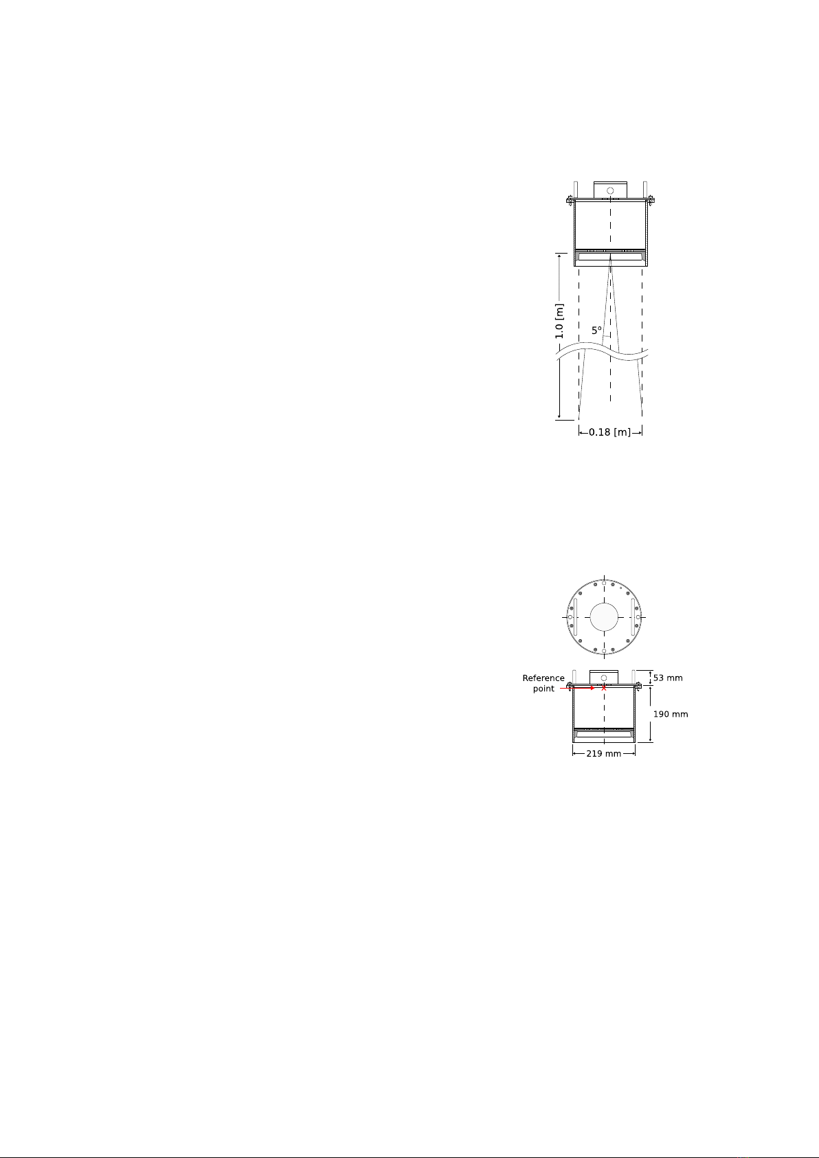
Figure 1.1: The 5 o[deg] half
top angle of the F08 antenna
beam.
Figure 1.2: Radar dimentions
and the zero reference point.
Note that the reference point
is located at the crossing of the
central axis with the lower sur-
face of the mounting flange.
The WaveGuide Onboard 2 is a dedicated sensor for measuring
waves and waterline level from a vessel mounted position. For
obtaining the best results from a WaveGuide Onboard 2 the
following radar positioning criteria must be taken into account:
• It is advised to choose a mounting position such that the
WaveGuide radar beam is free of large reflecting obstacles
(the beam of the F08 antenna can be approximated to a
conical shape having a 5◦[deg] half top angle as shown
in Fig. 1.1). The minimum horizontal distance between
a sensor and any obstacle in the beam’s path should be
at least 10% of the vertical distance between the sensor
and the obstacle. This does not only include horizontal
objects in the beam’s path but also vertical structures.
• Any structure that the WaveGuide sensors are mounted
to might have some influence on the waves progressing
around it. Hence, it is advised to mount the sensors at
a position facing the mean wave direction so that they
can measure the least disturbed water surface. As each
vessel has a unique shape, it is the user’s responsibility
to carefully identify the best position for mounting the
WaveGuide radar. In most cases the vessel’s bow provides
the optimal mounting position.
• The minimum measuring distance is at 2 meter. As such,
the sensor should be mounted with its reference point at
least 2 meter above the highest expected waterlevel during
the period in which the water surface is monitored. The
reference level for the mounting height of the radars is
shown in Fig. 1.2.
• The expected roll and pith motion of the vessel should
be taken into account when mounting the sensor. For
optimal performance, the resulting sensor attitude during
operation must not exceed 15◦[deg] of tilt from vertical. It
is good practice to align the sensor’s tilt axis with the most
stable vessel axis. For example, tilting the sensor along a
ships longitudinal axis when the expected maximum pitch
angles are lower than the maximum roll angles. At the
same time the sensor must be pointed away from the vessel
to avoid radar reflections from the vessel’s body.
4

1.3 Installation
Figure 1.3: Optional mounting
plate for the WaveGuide radar.
Figure 1.4: Top view of the hori-
zontal mounting beams.
Figure 1.5: Optional frame that al-
lows mounting of the WaveGuide
radar at different angles.
To facilitate the mounting of the WaveGuide radar, an op-
tional mounting plate is available upon request (Part no.
WG-MP-SS). Figure 1.3 shows a sketch of the optional
mounting plate and its dimensions.
The mounting plate can be fixed to two horizontal beams
(Fig. 1.4). The length of the beams must take into account
the minimum horizontal distance between the WaveGuide
radar and any obstacles in the path of the radar signal (as
explained in the radar positioning criteria).
The outside diameter of the WaveGuide radar cylinder is 219
[mm] and the total height of the system is 245[mm]. The
radar cylinder has a flange (265 [mm] diameter) that con-
tains 4 mounting holes each having a diameter of 11 [mm].
It is advised to mount the horizontal beams first. Then to
attach the mounting plate to the horizontal beams and fi-
nally to mount the WaveGuide radar to the mounting plate.
The optional mounting plate has 4 threaded mounting holes
(M10 thread) for mounting the WaveGuide radar to the
mounting plate.
Upon request, Radac can supply an optional frame (Part
no. WG-MH-SS) that allows for mounting the WaveGuide
radar and mounting plate at angles 0, 5, 10, 15 and 20 [deg]
away from vertical (see Fig.1.5). The radar mounting plate
(Part no. WG-MP-SS) is included with this frame as well
as brackets to allow mounting the frame to a handrail.
5

Chapter 2
Wiring
2.1 WaveGuide radar
Figure 2.1: Block diagram of the
Waveguide Onboard 2 system.
A cable gland (IP68-10bar and IP69K certified) is pre-
installed on the WaveGuide sensor for use on the terminal
compartment as a watertight cable entry point. The sup-
plied gland allows the installation of insulated cables from
8 to 15 [mm] in diameter.
When selecting a cable for use with a WaveGuide system,
the following specifications must be used:
• Two wires for power transmission, the choice of power
supply will influence the diameter and insulation thick-
ness of those wires.
• Four wires for data transmission, at least satisfying
Category 5e Ethernet cable (Cat 5e) specifications.
• The cable must be shielded and can have a maximum
length of 80 [m].
Figure 2.2: Terminal compartment
and connections.
Upon request, Radac can supply an optional cable that com-
plies with the WaveGuide system requirements for power
and data transmission.
The terminal compartment contains a six pole and a two
pole connector as well as a ground connection point, as
shown in Fig. 2.2. The six pole connector is used to connect
the Ethernet data wires. The poles labeled with Tx+, Tx-,
Rx+ and Rx- relate to RJ45 pins 1,2,3 and 6. Additionally
a reset function is implemented on the top two poles, which
should only be temporarily connected when resetting the
radar to its factory settings or setting a fixed IPV4 address.
The 2nd connector (2 pole connector) in the terminal com-
partment is used to supply the system with either 24-65VDC
or 65-240VAC power. The poles are labeled as +/~ and -/~,
yet the internal power supply operates also when the + and
- poles are switched around.
Please do take into account the voltage drop due to wire
resistance between the power supply unit and the radar, the
radar must at all times receive more than 21.0 VDC. For
this reason, to be sure to stay within the limits, at longer
distances it is advised to use a 36VDC or a 48VDC power
supply.
6

The cable shielding must be connected to ground at both ends of the cable.
Label RJ45 Profinet Color
Tx+ 1 Yellow
Tx- 2 Orange
Rx+ 3 White
Rx- 6 Blue
Table 2.1: Ethernet wiring instruction.
Note
Connecting the Reset poles for for 0.5 to 2 seconds during operation will cause the sensor
to temporarily use the default IPV4 address 192.168.111.71 until the system is rebooted.
Connecting the Reset poles for longer than 10 seconds during operation will cause the
sensor to reset to default factory settings and reboot. The indicator LED will flash
rapidly during this procedure. Refer to Appendix 3: LED blinking modes for a
description of the LED blinking modes.
Warning
Improper wiring can damage the radar’s communication board. Always check that power
is applied to the right connector before connecting it!
Warning
Make sure the housing of the device is properly connected to the ground reference! Make
sure the electrical resistance of the ground connection is below the maximum prescribed
by local requirements!
Upon powering the system the status LED will turn on and continue to shine while the
system is starting up. When the startup process is completed and the system is running in
normal mode, the LED will blink twice for half a second after which it will remain offfor 4
seconds. Any other blinking mode will warn you that the system is not functioning in its
normal mode of operation. See Appendix 3: LED blinking modes for a description of the
different LED blinking modes.
7

Chapter 3
WaveGuide system commissioning
With all the wiring in place as described in the previous chapter, the system can be con-
figured using the following steps (explained in the current chapter):
1. Connect the WaveGuide system to a computer.
2. Become an authorized user.
3. Configure the system.
4. Perform a system check.
5. Configure the distribution of data.
Step 1. Connect the WaveGuide system to a computer
Once the WaveGuide system is connected to a Local-Area-Network, communication can be
done via the available web interface (Fig. 3.1). For this purpose any web browser with
JavaScript enabled can be used.
Figure 3.1: The web interface of the WaveGuide OnBoard 2 sensor.
Note
A computer can be connected to the WaveGuide processing unit directly using a network
cable (a crossover cable is not required).
8

By default, during startup the WaveGuide system tries to obtain an IPV4 address by
searching the Local-Area-Network for a DHCP server.
If a DHCP server is available and the WaveGuide sensor completes the startup process, its
IPV4 address can be found using a Zeroconf browser such as Avahi or Bonjour.
If a DHCP server is not available, a temporary fixed IPV4 address can be set by connecting
the two reset poles in the sensors terminal compartment for 0.5 to 2 seconds. This will cause
the sensor to use the default IPV4 address 192.168.111.71 until it is rebooted allowing the
user to access and change the network settings to the desired fixed configuration.
Note
In order to access the user interface both the computer and the sensor must be on the
same IPV4 address subnet.
The WaveGuide sensor homepage contains three main sections (Dashboard, Configuration
and Status) as listed in Table 3.1.
Link Description
Dashboard Visualisation of the measured data.
Configuration Changing the settings and configuration of the system.
Status System state overview and general information.
Table 3.1: Description of the WaveGuide system main sections.
9

Step 2. Become an authorised user
To modify the WaveGuide system’s configuration you need to be an authorized user. There-
fore, an authorization dialogue will appear when the user enters the configuration page.
The authorization will be valid for a duration of 30 minutes. However, the web browser may
store the login name and password. In that case, the authorization data will be submitted
automatically by the browser without a pop-up dialog. The default login password is
“radac”.
After a successful authorization, the user can view and change settings. After submitting
any new settings a reboot dialog will appear. To ensure proper initialization of the new
settings, the WaveGuide system must be rebooted.
Figure 3.2: Login page.
10

Step 3. Configuration
The configuration page contains five sections as listed in Table 3.2.
Link Description
Date&Time For viewing and setting the system time.
Network For viewing and changing the network settings.
Sensor For viewing and changing the sensor specific settings and for view-
ing reflection diagrams.
Subscriptions To set up data export over the network.
Data Logger To view logged data.
Table 3.2: Description of configuration page sections.
Step 3.1: Set system date and time
In order to ensure an accurate timestamping of the data, the WaveGuide system runs an
NTP time service to automatically correct its system time to UTC time. For the NTP
service to work, the system needs to be connected to the Internet, as it needs to be able to
reach its default NTP servers.
In the case that the NTP servers can not be reached, it is possible to manually set the
system date and time using the "Date&Time" menu (Fig. 3.3). Adjusting the date and
time while the NTP service is running is not possible as the time will be automatically
corrected back to UTC time. The date and time are kept by an on-board clock. Please be
aware that such on-board clocks are not highly accurate and can drift over the years while
the system is used; it is thus advised to use the NTP service.
Figure 3.3: Setting the system time and date.
If the WaveGuide system is not connected to the Internet but instead connected to a local
11

network that includes a time server, then the system can be adjusted to synchronize time
and date with the local time server using the "Set NTP" button and submitting the local
NTP server address.
Step 3.2: Adjust network settings
Figure 3.4: Adjusting the network settings.
The network settings can be modified via the web-interface (Fig. 3.4). It is advised to use
the default setting, to automatically obtain the network settings from a DHCP server, and
assure from the side of the DHCP server that the system will receive the same IP-address
at all times. This setting provides the easiest setup and ensures the correct settings for the
local network.
Note
To ensure an accurate system time, the WaveGuide system is by default configured to use
an NTP time service. For this service to work, a connection to the Internet is necessary.
Note
Configuring the use of a static IP could disable the NTP service when the system is not
able to reach any nameserver. The user interface allows to manually add or remove
nameserver addresses.
Step 3.3: Sensor configuration
The WaveGuide Onboard 2 is designed with a high level of flexibility in mind, to apply
to every possible mounting situation. The sensor menu allows the configuration of those
parameters that are specific to the sensor installation. The mounting height above the
reference water level, and possibly a number of other parameters, needs to be set for each
12

specific mounting location. This can be done in the configuration table that is shown in
Fig. 3.5.
Figure 3.5: Setting sensor parameters (changes only take effect after the system is rebooted).
Mounting height
The mounting height is defined as the height of a radar above the reference water level in
[m]. The reference point for measuring the height of each radar is the lower-side of the
radar mounting flange (as shown in Fig. 1.2). By default, the mounting height is set to
zero [m].
Max. range
The range maximum in [m] is the maximum distance at which the sensor will detect the
water level. In general there is no need to modify this parameter. Yet in some situations
it is advised to set this parameter to a value lower than two times the distance from the
radar to the lowest expected water level. This is to avoid detecting multiple echoes of the
same measurement sweep.
Min. range
The range minimum in [m] is the minimum distance at which the sensor will detect the
water level. This parameter is used to avoid spurious measurements and should be set
depending on the installation location. If there are any nearby surfaces that can reflect the
radar signal the range minimum should be set to a value higher than the distance to those
reflecting surfaces. The range minimum parameter should not be lower than 2 [m] to avoid
interference with the internal reflection in the radar antenna.
Min. signal
The signal minimum is the lower limit for the signal power that will be considered in
water level measurements. This parameter is by default set to 25 [dB], and should only be
adjusted by an expert user.
Reflection diagram
The reflection diagram gives a snapshot of raw radar data in the frequency domain. The
13

reflection diagram provides a useful insight in the quality of the reflection signal that is
obtained by the radar.
After changing the sensor parameters for the radar, rebooting the system is required for
the changes to take effect. The reflection diagram of the sensor should be checked to ensure
that the water level measurement is within the defined limits (More information can be
found in ’Step 4.2: Check the Reflection Diagrams’).
14

Step 4. Perform system check
This section explains how to inspect the quality of measurements after configuring and
rebooting the WaveGuide system (the start-up process can take up to 5 minutes).
Step 4.1: Check system information
The system information table can be reached through the status menu item on the top-right
of the web interface. The system info page displays the communication status (as shown in
Fig. 3.6). A communication status "INIT" indicates that the WaveGuide system is starting
up. Once the system has started (a process that can take up to five minutes after power-up)
the displayed status becomes ’OK’.
Figure 3.6: System information.
In the same table, the ratio between the number of performed and invalid measurements
gives an indication of the system performance. When the system is setup in a correct man-
ner, the number of invalid measurements should be below 10% of the number of performed
measurements. However, during the start up and communication initiation processes the
number of invalid measurements can grow to over 1000 (temporarily increasing the ra-
tio between invalid measurements and performed measurements). The number of invalid
measurements will show a slow increase after the initial invalid measurements.
15

Step 4.2: Check reflection diagrams
The reflection diagram for each sensor can be accessed via the sensor configuration page by
clicking on the corresponding "reflection" button (Fig. 3.7).
A reflection diagram is a graphic representation of a 25 [ms] scan, where the signal strength
[dB] is plotted against the measurement distance [m]. A scan consists of one up-sweep
(increasing frequency, blue curve) and one down-sweep (decreasing frequency, red curve).
Often several peaks are visible in a reflection diagram as shown in Fig. 3.7. This is caused
by the multiple signal reflections between radar, water surface and any objects within the
radar foot-print. The leftmost peak is generated by the so called internal reflection. The
signal processing takes this phenomenon into account such that it does not have a negative
effect on the measurements.
Figure 3.7: The reflection diagram gives a graphical representation of the
radar signal received in a single measurement.
Based on the defined range maximum and minimum values, the WaveGuide system shows
the applied boundaries using vertical green lines. A horizontal green line shows the min-
imum accepted reflection strength (the value set as the Signal Minimum [dB] parameter).
The three green lines together form a region in which a measurement is accepted, and any
result outside of it is ignored.
Step 4.3: Check the measurements
On the ’Dashboard’ page, the parameters heaveRadar, heaveIMU and heaveWOB show the
distances measured during the last 1, 3 and 10 minutes. The heaveRadar parameter shows
the (non-motion-corrected) instantaneous waterlevel within the radar-fixed reference frame.
The heaveIMU shows the radar’s vertical motion as measured by the IMU. The heaveWOB
shows the corrected instantaneous waterlevel as would have been measured from a non
moving object. Note that, as a result of filtering, the heaveIMU and heaveWOB output
have between 100 and 120 [sec] of delay.
Please inspect the available heave graphs to visually confirm the measured data. Other
calculated parameters are available for viewing on the dashboard page. Please take into
account that it can take up to 10 minutes to gather enough raw data to calculate the
parameters.
16

Figure 3.8: Dashboard view.
17
This manual suits for next models
1
Table of contents
Popular Marine Radar manuals by other brands

Furuno
Furuno 1932 MARK-2 installation manual

Megasat
Megasat Countryman GPS user manual

Humminbird
Humminbird HELIX GPS Operation manual

Garmin
Garmin GMR 404 xHD Open Array and Pedestal Declaration of conformity

Furuno
Furuno FAR-2107 Series Service manual

Furuno
Furuno FR/FAR-2835SW/2865SW installation manual