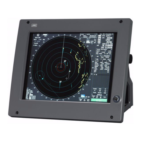
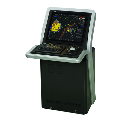
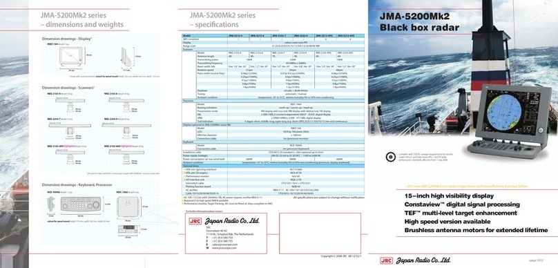
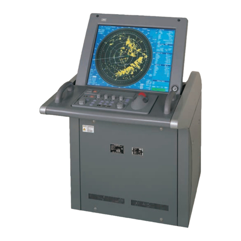
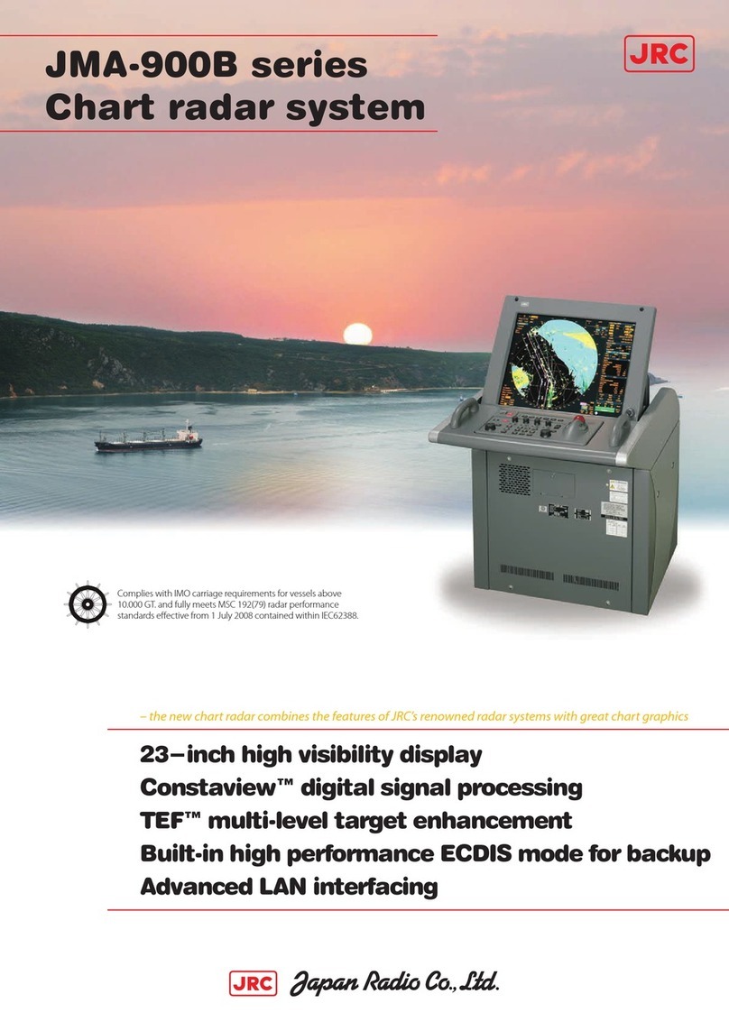
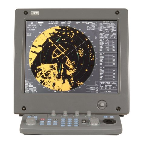
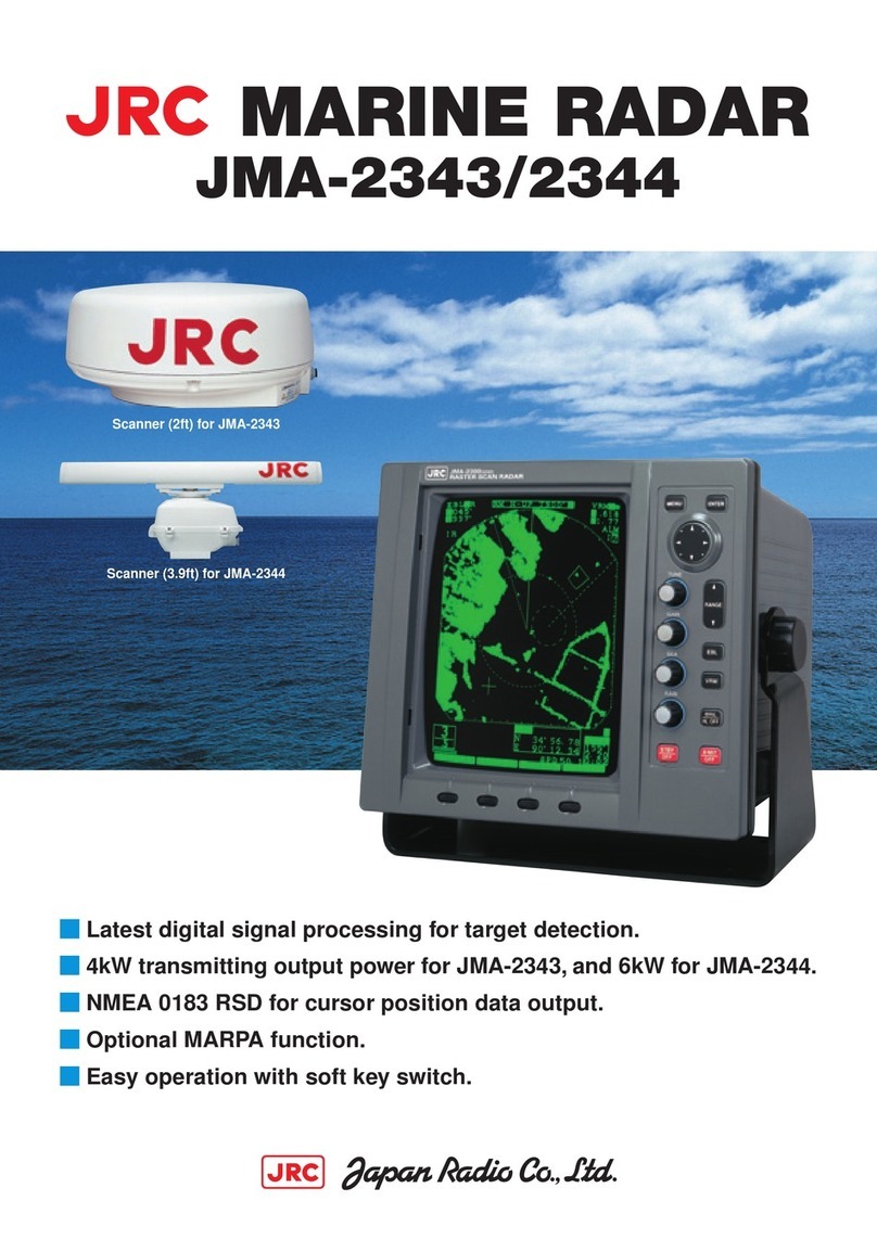
JRC JMA-5212-4 User manual

MARINE RADAR
MARINE RADAR
EQUIPMENT
EQUIPMENT
INSTALLATION
INSTALLATION
MANUAL
MANUAL
JMA-5212-4/6
JMA-5212-4/6
JMA-5222-7/9
JMA-5222-7/9
JMA-5212-4HS/6HS
JMA-5212-4HS/6HS
%1&'0Q<24&
1%6'FKVKQP,4%


CONTENTS
1. OVERVIEW
2. INSTALLATION OF THE SCANNER
2.1 SELECTING THE INSTALLATION POSITION ........................................ 2-1
2.2 INSTALLATION PROCEDURE ................................................................ 2-5
2.3 CONNECTING THE INSTALLATION CABLE (NKE-2103) ..................... 2-9
2.4 CONNECTING THE INSTALLATION CABLE (NKE-2254) ....................2-11
3. INSTALLATION OF THE DISPLAY UNIT
3.1 SELECTING THE INSTALLATION POSITION ........................................ 3-1
3.2 INSTALLATION OF THE LCD MONITOR................................................ 3-2
3.3 INSTALLATION OF THE OPERATION UNIT .......................................... 3-4
3.4 INSTALLATION OF THE POWER CABLE (CFQ-5436).......................... 3-5
3.5 INSTALLATION OF THE CABLE (CFQ-6912)
BETWEEN THE RADAR PROCESS UNIT AND THE SCANNER .......... 3-8
3.6 CONNECTING TO THE GPS RECEIVER.............................................. 3-10
3.7 CONNECTING TO THE GPS COMPASS .............................................. 3-15
3.8 CONNECTING TO NMEA HEADING OUTPUT DEVICE....................... 3-23
3.9 CONNECTING TO THE GYRO AND ELECTROMAGNETIC LOG
(NSK UNIT SETTING) (OPTION)........................................................... 3-25
3.10 CONNECTING TO THE PC PLOTTER.................................................. 3-31
3.11 CONNECTING TO OTHER NMEA DEVICES ........................................ 3-32
3.12 CONNECTION WITH OTHER DEVICES
(SUB INDICATOR OUTPUT AND SLAVE INPUT) ................................ 3-34
3.13 POWER SUPPLY (NBA-5111) (OPTION) .............................................. 3-38
3.14 TARGET TRACKING (NCA-877A) (OPTION) ....................................... 3-39
3.15 PLOTTER CIRCUIT (NDB-44) (OPTION) .............................................. 3-41
3.16 CONNECTING TO AIS (NQA-2155) (OPTION) ..................................... 3-43
3.17 COASTLINE ROM CARD/MEMORY CARD .......................................... 3-47
3.18 CONNECT SLAVE MONITOR / VDR..................................................... 3-50
3.19 SIMPLIFIED INTER-SWITCH INSTALLATION...................................... 3-52
3.20 SUB KEY-BOARD INSTALLATION....................................................... 3-54
3.21 CONNECTING TO EXTERNAL BUZZERS............................................ 3-56
3.22 CONNECTING CONTACT SIGNALS TO EXTERNAL DEVICES.......... 3-58
ġ
4. INITIAL SETTING
4.1 HOW TO OPEN THE EQUIPMENT SETUP MENU..................................4-1
4.2 TUNE ADJUSTMENT ...............................................................................4-2
4.3 BEARING ADJUSTMENT ........................................................................4-5
4.4 RANGE ADJUSTMENT............................................................................4-6
4.5 SETTING OF TRUE BEARING VALUE....................................................4-7
4.6 ANTENNA HEIGHT SETTING (ANTENNA HEIGHT)...............................4-8
4.7 SETTING OF CCRP/ANTENNA/GPS ANTENNA POSITION
(CCRP SETTING) .....................................................................................4-9
4.8 COMMUNICATION PORT SETTING (COM PORT SETTING)............... 4-11
4.9 SECTOR BLANK SETTING (SECTOR BLANK)....................................4-17
4.10 TNI BLANK SETTING (TNI BLANK)......................................................4-19
4.11 SETTING OF PULSE OUTPUT SELECTION
(BEARING PULSES FROM ANTENNA) ................................................4-20
4.12 LANGUAGE SETTING (LANGUAGE) ...................................................4-21
4.13 DATE TIME SETTING.............................................................................4-22
4.14 MAIN BANG SUPPRESSION ADJUSTMENT (MBS) ............................4-23
4.15 ADJUSTMENT OF PERFORMANCE MONITOR (MON) .......................4-25
4.16 MAGNET COMPASS SETTING .............................................................4-27
4.17 GPS RECEIVER SETTING.....................................................................4-28
4.18 DGPS RECEIVER SETTING ..................................................................4-37
4.19 SBAS RECEIVER SETTING ..................................................................4-41
4.20 DISPLAYING GPS RECEPTION STATUS .............................................4-46
4.21 SIMPLIFEDINTER-SWITCH SETTINGS ................................................4-48
5. MEASURES AGAINST NOISE INTERFERENCE IN THE
RADIO EQUIPMENT
5.1 SHIELD OF DEVICES ..............................................................................5-1
5.2 INTER-UNIT CABLES ..............................................................................5-1
5.3 INSTALLATION LOCATION .....................................................................5-1
5.4 GROUNDING............................................................................................5-1

6. INSPECTION AFTER INSTALLATION
6.1 INSPECTION AFTER INSTALLATION .................................................... 6-1
6.2 OPERATION INSPECTION...................................................................... 6-1
APPENDIX
FIG.1 NKE-2103-4 OUTSIDE DRAWING
FIG.2 NKE-2103-6 OUTSIDE DRAWING
FIG.3 NKE-2254-7 OUTSIDE DRAWING
FIG.4 NKE-2254-9 OUTSIDE DRAWING
FIG.5 NWZ-164 OUTSIDE DRAWING
FIG.6 NDC-1460 OUTSIDE DRAWING
FIG.7 NCE-7699A OUTSIDE DRAWING
FIG.8 NBA-5111 OUTSIDE DRAWING
FIG.9 GENERAL SYSTEM DIAGRAM OF RADAR TYPE JMA-5212-4/6
FIG.10 GENERAL SYSTEM DIAGRAM OF RADAR TYPE JMA-5222-7/9
FIG.11 JMA-5212-4/6, JMA-5222-7/9 POWER SYSTEM DIAGRAM
FIG.12 NDC-1460 INTERNAL CONNECTION DIAGRAM OF RADAR PROCESS
UNIT
FIG.13 NCE-7699A INTERNAL CONNECTION DIAGRAM OF KEY-BOARD UNIT
FIG.14 NKE-2103 SCANNER UNIT INTERCONNECTION DIAGRAM
FIG.15 NKE-2254 INTERCONNECTION DIAGRAM OF SCANNER UNIT
FIG.16 JMA-5212-4/6 INTERCONNECTION DIAGRAM
FIG.17 JMA-5222-7/9 INTERCONNECTION DIAGRAM

ġ

3
4
5
2
1
6
APPENDIX
1 OVERVIEW
2 INSTALLATION OF THE SCANNER
3 INSTALLATION OF THE DISPLAY UNIT
4 INITIAL SETTING
5 MEASURES AGAINST NOISE INTERFERENCE IN
THE RADIO EQUIPMENT
6 INSPECTION AFTER INSTALLATION
APPENDIX

ġ

SECTION 1
OVERVIEW

1-1
The proper installation of the radar equipment is critical in ensuing its effective and reliable performance as
well as facilitating maintenance and repair. Therefore, carefully install the radar equipment by following the
procedures below:
1) Install the scanner as high as possible while taking the scanner's weight into consideration.
2) It is preferable to install the display unit in the wheel house to facilitate observations.
3) Available cable lengths for installing the radar JMA-5200MK2 are as shown in the table below.
Request an appropriate cable from JRC beforehand. A cable longer than the sufficient length may
degrade radar performance, so give it careful consideration when planning the installation.
Code No. Cable length (number of cores)
CFQ6912-10 10 m (19 cores)
CFQ6912-15 15 m (19 cores)
CFQ6912-20 20 m (19 cores)
CFQ6912-30 30 m (19 cores)
CFQ6912-40 40 m (19 cores)
CFQ6912-50 50 m (19 cores)
CFQ6912-65 65 m (19 cores)

SECTION 2
INSTALLATION OF THE SCANNER
2.1 SELECTING THE INSTALLATION POSITION ........................................2-1
2.2 INSTALLATION PROCEDURE ................................................................2-5
2.3 CONNECTING THE INSTALLATION CABLE (NKE-2103) .....................2-9
2.4 CONNECTING THE INSTALLATION CABLE (NKE-2254) ...................2-11

2-1
2.1 SELECTING THE INSTALLATION
POSITION
1) Physical selection criteria
xInstall the antenna at the center of the mast on the keel line.
xIf the antenna cannot be installed at the above position for some reason, the amount of
deviation must be minimized. And, reinforce the mount base and the platform and take
precautions to protect the antenna from vibration and impact at the installation position.
xTo avoid the radiating section coming in contact with other installed objects while it is
rotating, ensure that there is at least 200 millimeters from the swing circle (turning radius) to
other installed objects (Fig. 1). The swing circle of the JMA-5200MK2 radar's antenna is
as shown in Table 1.
Antenna model (length)ᴾSwing circleᴾ
ᵬᵩᵣᵋᵐᵏᵎᵑᵋᵔᴾᴾ ᵆᵔᴾᶄᶃᶃᶒᵇᴾ ᵏᵗᵏᵎᶋᶋᴾ
ᵬᵩᵣᵋᵐᵐᵓᵒᵋᵕᴾᴾ ᵆᵕᴾᶄᶃᶃᶒᵇᴾ ᵐᵐᵕᵎᶋᶋᴾ
ᵬᵩᵣᵋᵐᵐᵓᵒᵋᵗᴾᴾ ᵆᵗᴾᶄᶃᶃᶒᵇᴾ ᵐᵖᵐᵓᶋᶋᴾ
Table 1 Swing circle
Fig. 1 Installation of antenna

ġ
2-2
2
xAvoid having a rope or signal flag from winding around the radiating section thereby
preventing it from rotating.
xAvoid the effects of dust and heat caused by smoke from a chimney.
xWhen determining the appropriate antenna height and installation location, take into
consideration the reduction of vibration, the strength of the hull and the antenna mount base,
and maintenance properties.
xProvide for maintenance space: platform, safety link, hand rail, steps, etc.
2) Electrical selection criteria
xThe installation height of the antenna relates to the maximum detection distance. The
higher, the better. However, if it is too high, radio wave energy greatly attenuates above the
antenna's vertical beam width (the point -3dB from the peak of the main lobe). As a result,
it is difficult to detect a close-in target. Sea clutter also increases. Determine the
installation height by taking into consideration the weight, maximum length of the cable, and
maintenance after installation.
xIf the installation height of the antenna is low, it is difficult to detect a long distance target.
The ship's mast, derrick, and chimney interfere with radiating beam causing the range that
cannot be viewed on the radar display to increase.
Generally, the lowest antenna installation position is supposed to be on the A-B line shown in
Fig. 2.
In the case of the JMA-5212/5222 type radar, 2Tequals 20q.
Specifically, the antenna position is normally elevated so that the chimney and the
shrine-gate type mast do not interfere with radiating beam.
JMA-5212/5222: = 10°
Fig. 2 Lowest antenna installation height
#
$
ǰ

2-3
xIf it is considered that sufficient installation height cannot be provided when the antenna is
installed directly on the roof of the wheelhouse, use a mounting rack or radar mast (FIG.3).
Normally, when the antenna installation height is less than 2 meters from the roof of the
wheelhouse, provide a mounting rack assembled at an angle frame to install the antenna.
When the antenna installation height is 2 meters or higher from the roof of the wheelhouse,
provide a cylindrical radar mast to install the antenna. Consider the convenience of the
service staff who take care of installation, maintenance, adjustment, and repair of the
antenna by providing adequate footholds to the mounting rack and the radar mast.
Fig. 3 Mounting rack and mast for the antenna
xWhen installing the antenna, select a location where there are the fewest structural objects in
the surrounding area so that false images which interfere with target detection will not be
generated by signal reflection from other antennas, deck structures, and cargo. Only as a
guide, note that structural objects should not exist within the range of the vertical beam
width (Fig.4).
Vertical beam width of X-band: Approx. 20q(r10.0qwhen the height of the radiating
section is 0q)
Fig. 4 Antenna and the surrounding structural objects
ࡆࡓ
ᵠᶃᵿᶋᴾ ᶕᶇᶂᶒᶆᴾ
Installation Installation

ġ
2-4
2
When installing two antennas, provide a height difference so that those two antennas do not
enter each other's vertical beam width range.
xTo avoid interference with other equipment and to prevent radio noise from generating, do
not place the VHF antenna, GPS antenna, and INMARSAT's dome within the range of the
vertical beam width.
xKeep a record of installation height data. The data is necessary for the initial setting of the
display unit.
xMinimize the blind sector, and ensure the adequate view angle so that the blind sector does
not exist in the range 22.5qfrom side to rear (Fig. 5). Specifically, ensure a sufficient view
field in the straight front (relative bearing 000q).
Fig. 5 Ensuring view angle
xMagnetron which has strong magnetic force is included in the antenna. Install the antenna
at least 3 meters away from nautical instruments including magnetic compasses and
chronometers.
* If there is a concern that structural objects existing within the vertical beam width may
generate false images, equip the structural objects with a radio wave absorber. (There are
two types of absorbers: broadband type having no specific resonant frequency and
narrowband type which can absorb a band with a specific frequency. Use those where
applicable.) Furthermore, it is effective to install a metal reflector, which reflects radio
waves upwardly, between the antenna and a structural object so that the radar's radio wave
will not directly come in contact with the structural object.
Note: Because most radio wave absorbers have poor durability, some must be
replaced every year. When installing a reflector, the area to the rear of the
reflector becomes a blind sector. Therefore, minimize the size of the reflector.
* The above procedures for selecting an antenna installation position are described based on
the radar's antenna. Comprehensively select the antenna position by considering other
antennas' installation procedure manual, hull's structure, strength of the selected position,
and vibration.
3) Confirmation during test run
If the antenna vibrates a lot during test run, try to reduce or prevent vibration by reinforcing
the antenna mount base or using wire stays attached to the radar mast.
0qdirection
Make no blind sector

2-5
2.2 INSTALLATION PROCEDURE
1) Precautions for transporting and storing the antenna
xAn antenna is a heavy load. Be very careful about handling it.
xDo not allow the antenna fall on its side while it is stored or being installed.
xDo not apply rope to the antenna in the way that squeezes or deforms the radiating section.
xWhen hoisting the antenna by a crane, do not hoist it by attaching a belt or a rope only to
the antenna's radiating section as shown in Fig. 6.
xFor the X-band, wrap a cloth around the antenna's support section located at the bottom of
the radiating section, and then attach a belt or rope to it to hoist the antenna
(Fig. 8).
Fig. 6 Improper way to hoist
Fig. 8 X-band

ġ
2-6
2
2) Installation procedures
a) Maintain a flat level surface on which to install the antenna.
xUse sufficiently thick steel material and reinforcement material for the antenna's
installation surface (mount base) to reduce vibration and impact. Keep the mount base
flat and smooth.
xIf there is a partial gap between the mount base and the antenna chassis's legs, work on
the installation surface so that it becomes flat and smooth, or make adjustments by
inserting metal shims. If a gap exists and the antenna is tightly clamped, the chassis
will distort and become damaged by vibration.
b) Avoid using vibration-proof rubber and resin
xDo not insert an elastic body, such as vibration-proof rubber or resin, between the mount
base and the antenna chassis' legs. If rubber or resin is inserted, the amplitude of
vibration increases, resulting in the possibility of damage to the antenna. Furthermore,
if installation bolts become loose due to deterioration of rubber or resin, the antenna
may be damaged or fall from its mount.
3) Installation and clamping method
a) Installation direction
xInstallation should be done so that the cable gland is oriented toward the stern.
b) Bolts, nuts and tightening torque to be used
xUse stainless steel bolts for the antenna and uniformly tighten all of the bolts using
double nuts for each bolt so that the antenna will not become loose (Table 2).
xAlthough the length of the bolt will differ according to the thickness of the mount base,
use a bolt long enough so that more than 4 millimeters of thread protrudes beyond the
double nuts after the double nuts have been tightened.
Table 2 Length of antenna mounting bolts and tightening torque
Thickness of Mount Base Bolt Torque (N-m)
X-band 12 M10u55(mm) SUS304 40

2-7
c) Use of washer and corrosion-resistant measures
xAt the location where a bolt's head or nut comes in contact with the antenna chassis' legs
and the mount base, insert a plain washer which fits the bolt; and, at the location where
the nut comes in contact with the plain washer, insert a spring washer, and then securely
tighten the nuts (Fig. 9).
xTo prevent corrosion due to the contacts between different metals, such as the antenna
chassis' legs, installation surface, bolts, nuts, etc., cover the bolt's head and nuts with
sealant (Fig. 9).
Fig. 9 Use of washer and corrosion-resistant measures

ġ
2-8
2
d) Grounding and corrosion-resistant measures
xGround the antenna chassis and the installation surface (hull) by using an earth line.
Apply sealant to the connection portion of the earth line to prevent corrosion and
damage by vibration (Fig. 10).
Fig. 10 Grounding and corrosion-resistant measures

2-9
2.3 CONNECTING THE INSTALLATION
CABLE (NKE-2103)
Other manuals for JMA-5212-4
1
This manual suits for next models
9
Table of contents
Other JRC Marine Radar manuals

JRC
JRC JMA-7110-6XA User manual

JRC
JRC JMA-2253 Quick start guide

JRC
JRC JMA-3300 Series User manual

JRC
JRC JMA-9133-SA User manual

JRC
JRC JMA-7710-6 User manual

JRC
JRC JMA-5300 Series User manual

JRC
JRC JMA-5200MK2 - User manual

JRC
JRC JMA-5312-6 User manual

JRC
JRC JMA-1030 Series User manual

JRC
JRC JMA-5212-4/6 User manual

JRC
JRC JMR-7296-6X User manual

JRC
JRC JMA-5212-4/6 User manual

JRC
JRC JMR-5410-4X User manual

JRC
JRC JMA-5322-6HS User manual

JRC
JRC JMA-7133-SA User manual

JRC
JRC RADAR 1800 User manual

JRC
JRC JMA-9172-SA User manual

JRC
JRC JMA-3910-4 User manual

JRC
JRC JMA-9900 Series User manual

JRC
JRC JMR-92 Series Quick start guide