Rain Bird WS-PRO LT User manual

WS‐PROLTWeatherStation
InstallationManual
January 2012 GT27146

WS-PRO LT weather station 1
WSPROLTTableofContents
1.0Installation ................................................................................................................ 2
1.1PowerSources ...................................................................................................................................... 2
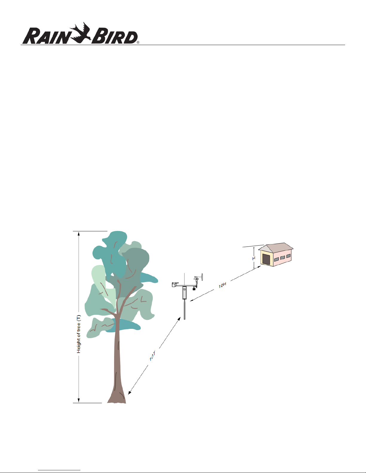
1.2SiteSelection......................................................................................................................................... 2
1.3Grounding ............................................................................................................................................. 3
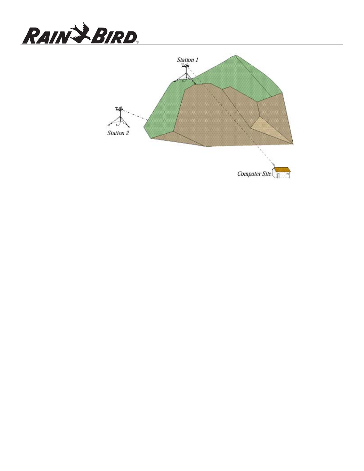
1.4WirelessCommunicationWeatherStation .......................................................................................... 3
1.4.1TransmissionsRanges ............................................................................................................ 3
1.4.2Line‐of‐Sight ........................................................................................................................... 3
1.4.3TestingRadioTransmissions.................................................................................................. 4
1.5DirectConnectWeatherStation ........................................................................................................... 4
2.0QuickStartGuide....................................................................................................... 5
2.1ComputerRequirements ...................................................................................................................... 5
2.2WeatherStationSetup ......................................................................................................................... 5
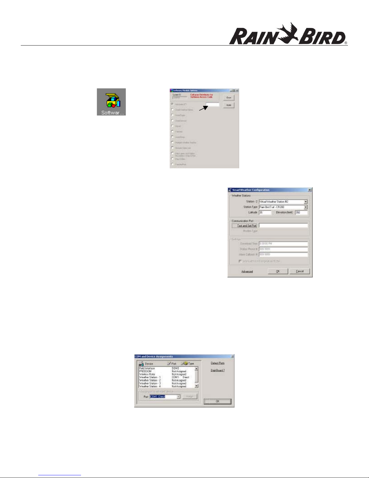
2.3WeatherStationConfiguration ............................................................................................................ 6
2.3VerifySerialCommunicationwithWeatherStation ............................................................................. 8
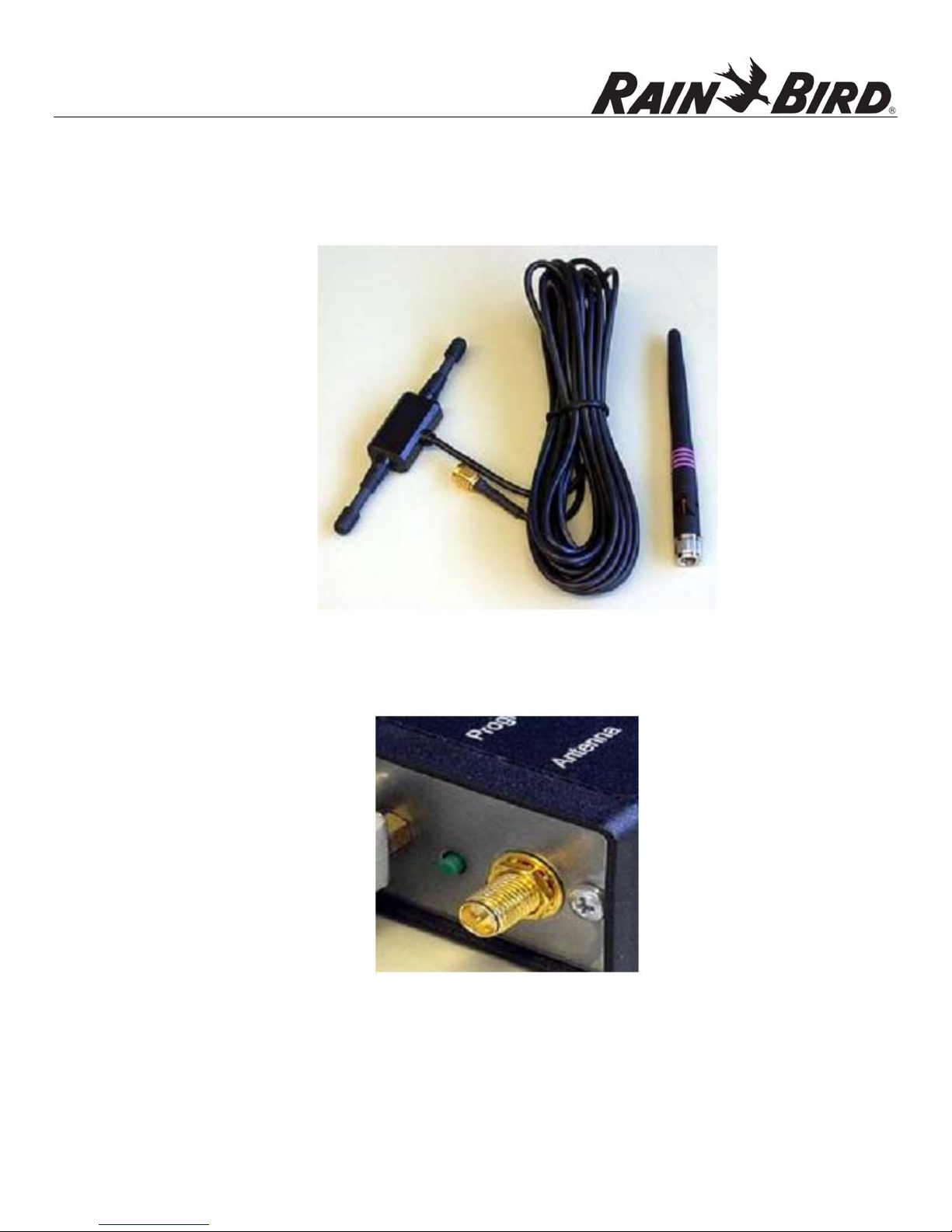
2.4RadioSetupforWirelessWeatherStations.......................................................................................... 9
2.5CommunicationWiringSetupforDirectConnectWeatherStations ................................................. 11
3.0InstallationProcedure .............................................................................................. 13
4.0SolarPanelInstallation............................................................................................. 15
AppendixA–GroundingRecommendations................................................................... 16
A.1.0GroundingSystemInstallation ........................................................................................................ 16
A.1.1GroundResistance............................................................................................................... 16
A.1.2InstallationRequirement..................................................................................................... 16
A.1.3groundRodStacking............................................................................................................ 17
A.2GroundingSystemDesigns ................................................................................................................. 18
A.2.1Design“Y” ............................................................................................................................ 18
A.2.2Design“Y”(Alternate).......................................................................................................... 19
A.2.3GroundingPlateDesign ....................................................................................................... 20

2 WS-PRO LT weather station
1.0 Installation
ThismanualcoverstheprocedureforinstallingyourWSPROLTweatherstation,forbothdirect
connectandwirelesscommunicationandforsolarandDCpoweredoptions.Beforeinstallingthe
weatherstation(s)atyoursite,readoverthediscussionsofpowersources,siteselection,grounding,
wirelesscommunicationanddirectconnectweatherstations.
2.1 Power Sources
Weatherstationshaveaninternalsealedrechargeablebatterythatmustberechargedto
assurecontinuedsystemfunction.Forrechargingthebattery,asolarpanelorausersupplied
externalDCpowersourcethathasanominalratingof18Vat1ampoutputisrequired.
2.2 Site Selction
Theidealsiteisrepresentativeofthegeneralarea,islevel,andwellawayfrom
obstructionssuchasbuildings,trees,andsteepslopes.Ifobstructionsexist,usetheTen
TimestheHeightRule,whichisillustratedinFigure1.
FIGURE1TenTimestheHeight
Rule
.

WS-PRO LT weather station 3
Forexample,iftheheightofthetreeTis8feetandtheheightoftheshedHis7feet,install
theweatherstationatleast80ftawayfromthetree(e.g.,10T=10x8=80ft)and70ftaway
fromtheshed(e.g.,10H=10x7=70ft).
Donotplacetheweatherstationnearasprinklerwhereitislikelytobesprayedbywater,
asthiswillchangetherainreportedbyweatherstation.
Note:Ifyourweatherstationwillbeinsideafencetodiscouragevandalism,thefencetop
mustbelowerthanthewindsensorsevenifthefenceischain‐link.
2.3 Grounding
Outdoorcablesmaybesubjecttoinducedcurrentsduetolightningorother
environmentalfactors.Therefore,propergroundingisimperativetoavoiddamageto
theweatherstationand/ortheHostcomputer.PleaseseeAppendixAforgrounding
recommendations.
2.4 Wireless Communication Weather Station
1.4.1 TransmissionsRanges
Wirelesscommunicationweatherstationsareavailableforinstallationswithinseveral
ranges.Typicaltransmissionrangesarelistedbelow:
•Upto½mile(0.8km)fortheweatherstation916MHzandweatherstation
922MHz
•Upto1/4mile(0.4km)fortheweatherstation2.40GHzofthecentral
controlcomputer.
•Upto7milesifanoptionalhighergainantennaisinstalledonboththe
weatherstationandtheRFXXXBaseStation
1.4.2 Line‐of‐Sight
Thisrangeassumesnoobstructionsareintheline‐of‐sight.Line‐of‐sightisdefinedas
astraightpathbetweenatransmittingandreceivingantennathatisunobstructedby
intermediatetopographyorobstructions.Aclearline‐of‐sightisrequiredtoachieve
theoptimumtransmissionrange.Theaffectofobstructionsonthetransmissionrange
canvary.Therefore,ifobstructionsliewithintheline‐of‐sight,youshouldtestyour
radiotransmissionsbeforepermanentlyinstallingyourweatherstation.

4 WS-PRO LT weather station
FIGURE2Line‐of‐sightexamples.Asthedottedlineindicates,Station1hasaclearline‐of‐sightwiththe
ComputerSite.ThemountainobstructsStation2’sline‐of‐sightandwouldreduceorpossiblyprevent
wirelesscommunications.
Wirelessweatherstationsareequippedwithspreadspectrumradiosandincludea
secondspreadspectrumradiothatisinstalledatthecentralcontrolcomputer.
1.4.3 TestingRadioTransmissions
Totesttheradiotransmissionofyourweatherstationcarrytheweatherstationto
thesitethenattempttocommunicatewiththecentralcontrolcomputer.If
obstructionsinthelineofsightarepreventingtheweatherstationfrom
communicating,trythefollowing:
•Relocateyourweatherstationawayfromobstructions
•Removetheobstructions
•Mountthecomputerbasestationantennaoutsideofthebuildingby
runningtheantennacablethroughawindoworcablerun
•Useahighergainantenna(optional)attheweatherstationsite
•Installahighergainantenna(optional)ontheroofofthecomputerbase
stationbuildingandalignitabovetheobstructions.
2.5 Direct Connect Weather Station
Directconnectweatherstationsareavailableforinstallationsthatrequiretheweather
stationbeplacedmorethana½milelineofsightfromthecentralcontrolcomputer.
Withtheuseofshorthaulmodems,theweatherstationcanbeinstalledupto2.4miles
awayusinga24AWGcable.
Note:DCE/DTEswitchesonthemodemsaresettoDCEatthecentralcontrolcomputer
andDTEattheweatherstation.

WS-PRO LT weather station 5
2.0 QuickStartGuide
2.1 Computer Requirements
•Cirrus,NimbusII,StratusII,orStratusLTcentralcontrolsystemwithAutomaticETand
MultipleWeatherStationmodules.ModulesareoptionalwithNimbusIIandStratusII
centralcontrolsystems.
Note:TheMultipleWeatherStationsmoduleisonlyrequiredifmultipleweather
stationswillbeconnectedtoonecentralcontrolsystem.
•Windows98/2000/XP,orWindows7OperatingSystem
•AvailableSerialPort/COMPort
2.2 Weather Station Setup
1. Removethetopfoampackingfromtheboxandverifyyouhaveallorderedequipment
(seeEquipmentList).ReportmissingordamagedequipmenttoyourlocalRainBird
distributorbeforeinstallingyoursystem.
Equipment
List
ModelsDirect
Connect
Direct
Connect
Solar
Powered
Wireless
Wireless
Solar
Powered
Wireless
2.4
GHz
Solar
Powered
1.WSPROLTWeatherStation
X
X
X
X
X
2.
RS‐232,serial
communicationscable(9‐
pinto9‐pin)
X
X
X
X
X
3.Twokeys
X
X
X
X
X
4.RF401‐seriesSpread
SpectrumRadio
X
X
5.RF416‐seriesSpread
SpectrumRadio
X
6.Antenna
X
X
X(whip)
7.RFXXXACAdapter
X
X
X
8.SolarPanel
X
X
X
9.SolarPanelMounting
Hardware
X
X
X
10.RADModemforcomputer
X
X
11.RADmodem(inwhite
box)forweatherstation
X
X

6 WS-PRO LT weather station
12.
Cableforconnection
betweenweatherstation
andRADmodemat
weatherstation
X
X
13.
Cableforconnection
betweenRADmodemat
weatherstationandMSP‐1
(9720)
X
X
2. Usetheliftstrapstoremovetheweatherstation,sinceremovingthestationbylifting
onthesensorsmaydamagethesensors(seeFigure3)
FIGURE3Lift
Straps
Note:Avoidrestingtheweatherstationonthewindspeedandwinddirectionsensors
3. Connecttheserialcable(maleconnector)totheweatherstation’sRS‐232port.Be
suretoremovedustcoverfromtheweatherstationRS‐232portbeforeconnecting
thecable.
4. Connecttheserialcable(femaleconnector)tocomputerserialCOMport
5. Connectpowertotheweatherstation(e.g.solarpower,usersuppliedDCpower)
6. TurnthekeytotheONposition.
2.3 Weather Station Configuration
1. RequestAutomaticETandMultipleWeatherStationsmodulekeycodesfromGlobal
ServicePlan(GSP)orfromyourlocalRainBirddistributor.
2. StartRainBirdcentralcontrolsoftware(e.g.Cirrus,NimbusIIorStratusII)

WS-PRO LT weather station 7
3. EnteryourkeycodebyclickingontheSoftwareModulesOptionsbuttonandentering
thekeycode(s)inthecorrespondingbox(seeFigure4)
FIGURE4KeycodeDialog
Box
4. ClickApplybutton
5. ClickClosebutton
6. ClickonToday’sET/WeatherDatabutton
7. ClickonWeatherStationConfigurationbutton
8. Selectweatherstationfromdropdownmenu(see
Figure5)
FIGURE5WeatherStationConfigurations
9. SelectStationTypeRainBirdTurf‐CR200
10. Enterlatitudeandelevationwhereweatherstationwillbeinstalled
11. AssignportbyclickingonTestandSetPort(seeFigure6)
Figure6TestandSet
Port
12. Selectweatherstation
13. SelectCOMPort(assigntoavailableCOMport)

8 WS-PRO LT weather station
14. ClickAssignbutton
15. ClickOKbutton
16. Enterdownloadtime
17. Repeatsteps8‐16for2nd,3rd,…,5thweatherstations
18. ClickOKwhenyouhavecompletethesetup
2.4 Verify Serial Communication with Weather Station
1. ClickonWeatherProgrambutton
2. Note:ToaccessWeatherProgramfrommainmenu,firstselectToday’sET/WeatherData
button
3. ClickonMonitorCurrentDatabutton
4. Monitorthesensordisplays.Withinacoupleofminutes,numericalvaluesshouldappearon
thescreenandindicatorlightsonthebottomoftheweatherstation,labeledScan/Receive,will
blinkeverytenseconds,confirmingcommunicationbetweentheweatherstationandthe
computer.
5. SynchronizetheweatherstationtimetothecomputertimebyclickingonSynchronizeWSTime
6. button
7. Closethemonitoringwindow
8. Disconnecttheserialcablefromtheweatherstationandplacethedustcoverbackontheserial
port.
9. ContinuewithRadioSetupforWirelessWeatherStationorfordirectconnectweather
stations,refertoCommunicationWiring…instructions.

WS-PRO LT weather station 9
2.5 Radio Setup for Wireless Weather Station
1. AttachantennatotheradioconnectorlabeledAntenna
FIGURE7Theradioantennamaybeasurfacemountantenna(left),awhipantenna(right)thatconnectsdirectly
totheradio,orotheroptionalantennas(notshown).
FIGURE8TheconnectormarkedAntennaonanRFXXX‐seriesradioiswheretheantennasattach.
2. ConnecttheserialcablemaleconnectortotheradioconnectorlabeledRS‐232

10 WS-PRO LT weather station
FIGURE9Radioconnections.Theserialcable(left)connectstothe
portmarkedRS232andtheACadapterconnectstotheportmarked
DCPWRinput.
3. ConnecttheserialcablefemaleconnectortoacomputerserialCOMport
4. PlugtheRF401ACadaptertotheRF401connectorlabeledDCPWRinput
5. PlugtheotherendoftheRF401ACadapterintoagroundedACwalloutlet.Thered
PWR/Txstatuslightshouldilluminate
6. ClickonWeatherProgrambutton
Note:ToaccessWeatherProgramfrommainmenu,firstselectToday’sET/WeatherDatabutton
7. ClickonMonitorCurrentDatabutton
8. Monitorthesensordisplays.Withinacoupleofminutes,numericalvaluesshouldappearon
thescreenandindicatorlightsonthebottomoftheweatherstation,labeledScan/Receive,
willblinkeverytenseconds,confirmingcommunicationbetweentheweatherstationandthe
computer.
9. Iftheradioisnotcommunicatingproperly,youmaybeexperiencinginterferencefrom
nearbyequipmentsuchaswirelessphones,otherspreadspectrumradios,oranother
weatherstation.Changethelocationoftheweatherstation.
10. Ifyourradioisworkingproperly,closetheweathersoftwareandturnthekeytotheoff
position.Youarenowreadytoinstallyourweatherstationatasitewithin½milefromthe
centralcomputer.

WS PRO LT weather station 11
2.6 Communication Wiring Setup for Direct Connect Weather Stations
1.FurnishandinstallaBelden#9883DirectBurialType,communicationcable
betweentheweatherstationandthecentralcontrolcomputer(nottoexceed
20,000ft./3.8mileswiththespecified20AWGBelden#9883cable).
Note:TheBeldencableshouldconsistofthree(3)twistedpairsofwires(20gauge),
abarecopperdrainwireandanaluminumshield.Thethree(3)twistedpairsshall
becolorcodedasfollows:one(1)blackandgreenpair,one(1)blackandredpair,
andone(1)blackandwhitepair.Theblackandwhitepairshallnotbeused,but
keptasasparepair.
Attheweatherstation…
2.ConnecttheBlack(‐xmt)andGreen(+xmt)pairofwires(ofthecommunicationcable)tothe
BlackandRedwiresrespectivelyonthe“Field”endofthefirstMSP‐1.
3.ConnecttheBlackandRedwiresonthe“Equipment”endofthefirstMSP‐1totheWhite
(‐xmt)andGreen(+xmt)wiresofthecable(9720)furnishedwiththeweatherstation.
4.ConnecttheRed(+rcv)andBlack(‐rcv)pairofwires(ofthecommunicationcable)totheRed
andBlackwiresrespectivelyonthe“Field”endofthesecondMSP‐1.
5. ConnecttheRedandBlackwiresonthe“Equipment”endofthesecondMSP‐1totheRed
(+rcv)andBlack(‐rcv)wiresofthecable(9720)furnishedwiththeweatherstation.
CommunicationWire
fromCentral
CommunicationWireat
WeatherStation
Black(‐xmt)
Green(+xmt)
Red(+rcv)
Black(‐rcv)
Black
Red
Red
Black
FIELD
FIELD
MSP‐1
MSP‐1
EQUIP
EQUIP
Black
Red
Red
Black
White(‐xmt)
Green(+xmt)
Red(+rcv)
Black(‐rcv)
FIGURE10Communicationwiringatweatherstation

12 WS-PRO LT weather station
6. GroundthebarecopperdrainwireoftheBeldencablealongwiththegreenground
wiresofbothMSP‐1surgepipestothegroundingrodusingabrassgroundwireclamp.
Note:Donotgroundthedrainwireatthecentralendofthecable.Leaveitunused.
7.LeavetheBlackandWhitepairofwiresasspares
8.Connecttheotherendofthecable(9720)totheComputerconnectiononthewhitebox
(containingRADmodem).
9.ConnecttheRS232endofthesecondcable(9721)totheRS232portoftheweatherstation.
10.Connecttheotherendofthecable(9721)totheWXStationconnectiononthewhitebox.
11.InstallthewhiteboxjustbelowtheweatherstationusingfurnishedUbolt.
Atthecomputer…
12. FurnishandinstallaBelden#9883orequivalent,directburialtype,communicationcable
betweentheRADmodeminstallednearthecentralcontrolcomputerandtheaccessboxatthe
centralvalveboxlocation.Specificationsofthiscablearelistedearlierinsection2.5.
13. ConnecttheBLACK(‐XMT)&GREEN(+XMT)pairoftheBelden#9883cablecomingfromthe
weatherstationtotheBLACK&REDwiresrespectively,atthe“FIELD”endofoneoftheMSP‐1
surgearrestors.TheBLACK(‐XMT)&GREEN(+XMT)wiresoftheBelden#9883communication
cablegoingtotheRADmodeminstallednearthecentralcomputershallbeconnectedtothe
BLACK&REDwiresrespectively,atthe“EQUIPMENT”endofthesameMSP‐1surgearrestor.
14. TheRED(+RCV)&BLACK(‐RCV)pairoftheBelden#9883cablecomingfromtheweather
stationshallbeconnectedtotheRED&BLACKwiresrespectively,atthe“FIELD”endofthe
otherMSP‐1surgearrestor.TheRED(+RCV)&BLACK(‐RCV)wiresoftheBelden#9883
communicationcablegoingtotheRADmodemshallbeconnectedtotheRED&BLACKwires
respectively,atthe“EQUIPMENT”endofthesameMSP‐1surgearrestor.
15. Connecttheblack(‐xmt)wiretothe(‐xmt)portoftheRadmodemfurnishedwiththeweather
stationkit.Useasmallscrewdrivertoopenthehole,insertthewireandthentightenwiththe
screwdriver.
16. Continuewiththegreen(+xmt),red(+rcv)andblack(‐rcv)wiresrespectively.
17. ConnecttheRADmodemtoaCOMportonyourcomputer(itmightbenecessarytousea9to
25pinconnector).

WS PRO LT weather station 13
3.0 InstallationProcedure
1. Mountamast/pole1.25”ODand8to10feet(312cm)highoncementbase.
2. Placeyourweatherstationassemblyontopofthemast/polewiththebasefirmlyseatedon
thetopedgeofthemast/poleof(seeFigure11)
FIGURE11
Installation
at
Pole
3. LooselytightentheU‐boltnutssothattheweatherstationisstablebutcanberotatedonthe
mast/pole.
FIGURE12U‐Bolt
Nuts
4. Asareference,useacompassandrotatetheweatherstationassemblyuntilthereferenceline
onthewinddirectionsensorisalignedwiththeMagneticNorth(seeFigure13).

14 WS-PRO LT weather station
N
N
FIGURE13WindDirectionAlignment
5. FirmlytightentheU‐Boltnuts
6. Confirmtheweatherstationislevelbyviewingthebull’slevelontopoftheweatherstation
(seeFigure
14).Minoradjustmentscanbemadebyplacingshimsbetweentheweatherstation
baseandthetopofthepole.
Bull’slevel
FIGURE14Bull'sLevelontopoftheweatherstation
7. Connectthepowersourcethatwillrechargetheinternalsealedrechargeablebattery.For
SolarPoweredweatherstationsfollowinstructionsbelow.
8. Removetheredcapfromthesolarradiationsensor(Figure15).
FIGURE15Solar
Radiation
Sensor
9. Properlygroundtheweatherstationbyconnectinga#10gaugeorlargerwiretotheearth
groundluglocatedonthebaseoftheweatherstation.ReferAppendixA
forgrounding
recommendations.
10. Refertosection2.5CommunicationWiringfordirectconnectweatherstations.

WS PRO LT weather station 15
11. TurnthekeytotheONpositionandreturntothecomputersitetoconfirmtheweather
stationisworkingproperly.
4.0 SolarPanelInstallation
Thesolarpanelrechargestheweatherstationinternalbattery.Ithasa72sq.inchsurfacearea
andproduces5watts,atapeakof17.1volts.
FIGURE165WSolar
Panel
1. Placethesolarpanelonthemastbelowthestationtothemaximumdistanceallowed
bythesolarpanelcable.
2. LooselytightentheU‐boltsothatthesolarpanelisstablebutcanberotatedonthemastor
pole.
3. Useacompasstoproperlyalignthesolarpanel.Ifyoursiteisinthenorthernhemisphere,
theglasssurfaceofthepanelshouldfacesouth.Ifyoursiteisinthesouthernhemisphere,
theglasssurfaceofthepanelshouldfacenorth.
4. ConnectthecabletotheweatherstationconnectorlabeledSolarPanel
5. TightenthethumbscrewandtheU‐bolt

16 WS-PRO LT weather station
AppendixA–GroundingRecommendations
A.1 Grounding System Installation
Topreventlightningdamagetoyourequipment,RainBirdrecommendsinstallingagrounding
systemfortheequipment(includingcontrollers,weatherstations,andcentralcontrolsystems).
Thegroundingsystemdischargeslightning‐inducedelectricalcurrentintotheearthratherthan
allowthesurgetopassthroughpowerwiresorfieldwirestoyourequipment’selectronic
components.
A.1.1 GroundResistance
Groundresistanceoccurswhengroundingsystemcomponents,orthesoilitself,oppose
theflowofelectricityintotheearth.Groundresistanceismeasuredinunitscalled
“ohms”(Ω).Thehigherthegroundresistance(higherohmreadings),thelesschancethe
surgewillbeshuntedtogroundratherthantotheequipment’selectroniccomponents.
FigureA.1‐1showspointswheregroundingsystemscandevelopresistance.Todecrease
groundresistance,RainBirdrecommendsirrigatingthesoilaroundthegrounding
system.Eachgroundingsystemshouldhaveadedicatedirrigationzonewithsprinkler
headsanditsownwateringprogramtomaintainsoilmoisturearoundthegrounding
system.
Aproperlyinstalledgroundingsystemshouldmaintainamaximumgroundresistanceof
10ohms,orless.Ifyouareunabletoreacharesistanceof10ohmsorless,youcan
decreaseresistancebysurroundingthegroundingrodsorplateswithground
enhancementmaterial,suchasPOWERSETfromPaigeElectricCorporation(P/N
1820058),orGEMfromERICO(P/NGEM‐25A).
Ifgroundresistancestillmeasureshigherthan10ohms,youcanextendthegroundrod
lengthasdescribedin“GroundRodStacking,”oruseadditionalgroundingrods,as
showningroundingsystemdesign“Y”(Alternate).
A.1.2 InstallationRequirement
Thefollowingrequirementsapplytoallgroundingsystemdesigns(designYandthe
“GroundingPlate”design).Allgroundingrodsorplatesmustbeconnectedtogether
belowgradewith#6AWGorlargersolidbarecopperwire.
Installtheconnectingwireinasstraightalineaspossible.Ifyoumustmakeaturnor
bendinthewire,maketheturninasweepingcurvewithaminimumradiusofeight
inchesandaminimumincludedangleof90o.

WS PRO LT weather station 17
Tominimizeresistance,thecopperwiremustbepre‐weldedtothegrounding
rods/plates,orweldedtotherods/platesusinganexothermicweldingprocessatthe
site.
Makesureallweldsaresecurebeforeburyingthegroundingrods.Rodsandplateswith
weldedjointsdonotneedperiodicvisualinspectionandcanbefullyburied(novalve
boxrequired).Measurethegroundresistancearoundthegroundingsystemafter
installation,andonceeveryyearafterthat.
Note:Thegroundwirefromtheequipmenttothegroundingsystemshould
beasshortaspossibleandhavenobends,kinks,orcoilsinthewire.
Inspectthegroundingsystem’sclampedconnectionstotheequipment(notthewelded
groundingsystemconnections)onceayeartomakesuretheyaresecureandcorrosion‐
free.
FIGUREA.1‐1Groundingsystemscandevelopresistanceatmanypoints\
A.1.3 GroundRodStacking
Threadedcouplers(showninFigureA.1‐2)aregroundrodsplices.Ifasinglegrounding
rodfailstoproduce10‐ohmgroundresistance(maximum),threadedcouplerscanbe
usedto“stack”groundingrods.
Note:Usethreadedcouplersmadeofthesamematerialasyourgroundingrods.
Stackinggroundrodsincreasesthetotaleffectiverodlength,decreasingground
resistance.Joiningtherodstogetherwiththreadedcouplersformsasecureconnection
sothegroundingrodscanbeassembledquicklyandeasily.

18 WS-PRO LT weather station
FIGUREA.1‐2Stackinggroundingsrodswiththreadedcouplerscanhelpdecreasegroundresistance
A.2 Grounding System Designs
A.2.1 Design“Y”
Design“Y”Design“Y”(showninFiguresA.2‐1andA.2‐2)consistsofthree,
5/8”‐diameterx8‐foot‐long,copper‐cladgroundingrods.Installtherodsinaradial1200
star(“Y”)configuration.Eachrodmustbeinstalledinatrueverticalposition,atleast16feet
fromtheequipment
Note:Allgroundingsystemdiagramsarenottoexactscale
FIGUREA.2‐1Design“Y”usesthreegroundingsrodsimnstalledinradial120degress“Y‐shaped”configuration

WS PRO LT weather station 19
FIGUREA.2‐2Groundingsystem“Ycanbeinstalledasshown,orwithgroundenchancementmaterialtoreducegroundresistance
evenfurther.
A.2.2 Design“Y”(Alternate)
Analternatedesign“Y”(showninFiguresA.2‐3andA.2‐4)usesthreeradialsina120
degreestar(“Y”)arrangement.Eachradialconsistsofthree,5/8”‐diameterx8‐footlong
copper‐cladgroundingrods.Thefirstrodineachradialmustbeatleasteightfeetfrom
theequipment.Therestoftherodsmustbeatleast16feetfromanyotherrod.
FIGUREA.2‐3Desing“Y”(Altrenate)usesninecopper‐cladgroundingrodsinstalledina120degreestarconfiguration
Table of contents
Other Rain Bird Weather Station manuals
Popular Weather Station manuals by other brands

La Crosse Technology
La Crosse Technology Wireless Weather Station instruction manual

FanJu
FanJu FJ3391-DCF manual

ACU-RITE
ACU-RITE 02001 instruction manual

Oregon Scientific
Oregon Scientific RMR966PA instruction manual

elsner elektronik
elsner elektronik Suntracer KNX basic Technical specifications and installation instructions

Oregon Scientific
Oregon Scientific BAR898HGA user manual