Rain Bird WS PRO LT User manual

WS PRO LT Weather Station
Installation Manual


WS PRO LT weather station 2
WS PRO LT
Weather Station
Installation Manual
This manual covers the procedure for installing your WS PRO LT weather station, for both direct connect
and wireless communication and for solar and DC powered options. Before installing the weather station(s)
at your site, read over the discussions of power sources, site selection, grounding, wireless communication
and direct connect weather stations.
Power Sources
Weather stations have an internal sealed rechargeable battery that must be recharged to assure continued
system function. For recharging the battery, a solar panel or a user supplied external DC power source that
has a nominal rating of 18 Vat 1 amp output is required.
Site Selection
The ideal site is representative of the general area, is level,and well away from obstructions such as
buildings, trees, and steep slopes. If obstructions exist, use the Ten Times the Height Rule,which is
illustrated in Figure 1.
Figure 1Ten Times the Height Rule.
For example, if the height of the tree T is 8 feet and the height of the shed H is 7 feet, install the weather
station at least 80 ft away from the tree (i.e., 10T = 10x8 =80 ft) and 70 ft away from the shed (i.e., 10H =
10x7 = 70 ft).
Do not place the weather station near a sprinkler where it is likely to be sprayed by water,as this will
change the rain reported by weather station.

WS PRO LT weather station 3
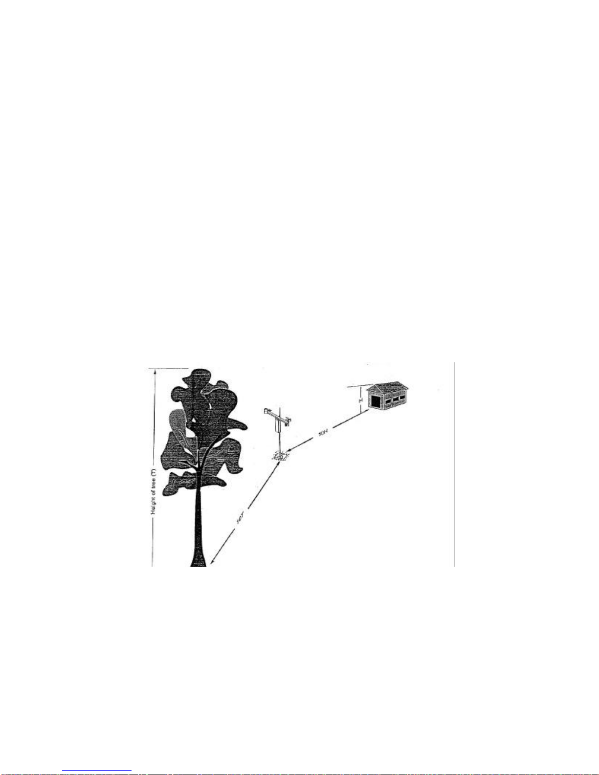
Note: If your weather station will be inside a fence to discourage vandalism, the fence top must be lower
than the wind sensors even if the fence is chain-link.
Grounding
Outdoor cables may be subject to induced currents due to lightning or other environmental factors.
Therefore, proper grounding is imperative to avoid damage to the weather station and/or the Host
computer. Review document D31910 for grounding recommendations.
Wireless Communication Weather Station
Wireless communication weather stations are available for installations within ½ mile / 0.8 km (1/4 mile /
0.4 km for 2.4GHz models) of the central control computer.
This range assumes no obstructionsare in the line-of-sight. Line-of-sight is defined as a straight path
between a transmitting and receiving antenna that is unobstructed by intermediate topography or
obstructions. A clear line-of-sight is required to achieve the optimum transmission range. The affect of
obstructions on the transmission range can vary. Therefore,if obstructions lie within the line-of-sight, you
should test your radio transmissions before permanently installing your weather station .
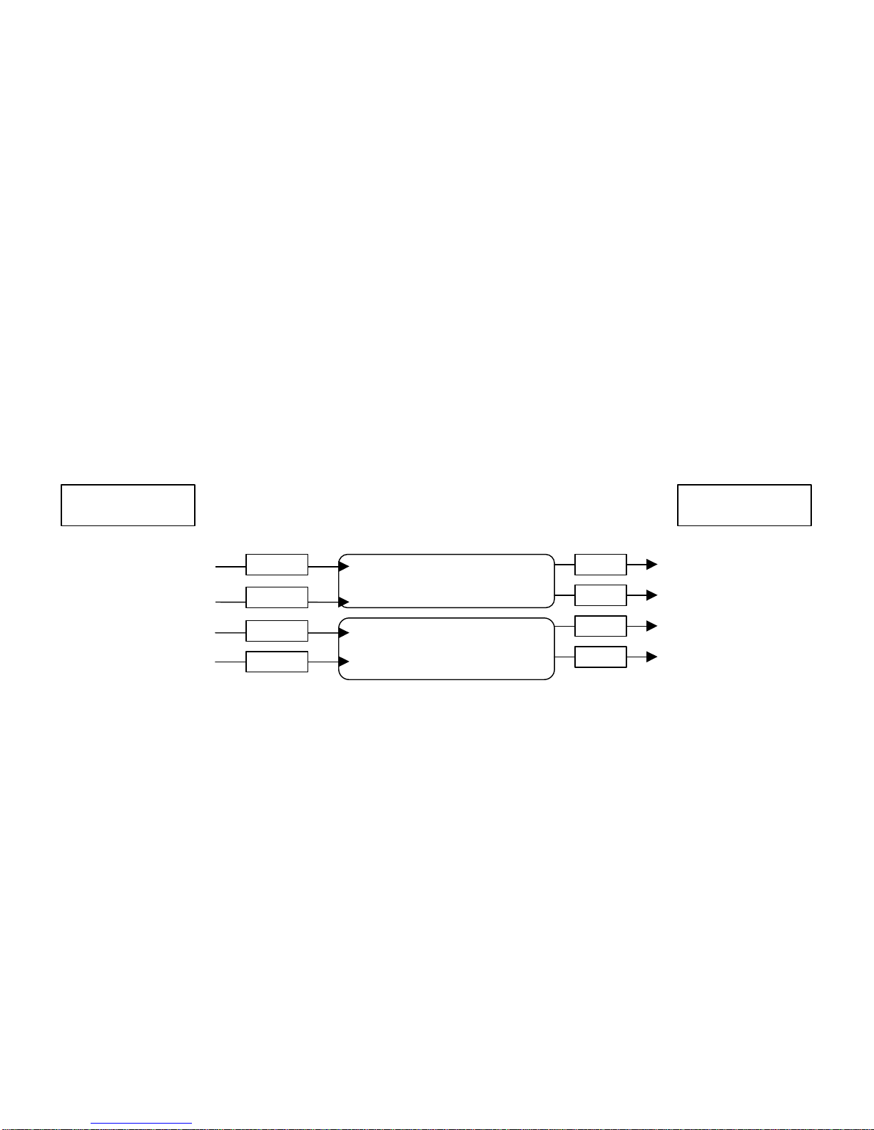
Wireless weather stations are equipped with spread spectrum radios and include a second spread spectrum
radio that is installed at the central control computer.
To test the radio transmission of your weather station carry the weather station to the site then attempt to
communicate with the central control computer. If obstructions in the line of sight are preventing the
weather station from communicating, try the following:
•Relocate your weather station away from obstructions
•Remove the obstructions
•Mount the computer base station antenna outside of the building by running the antenna cable
through a window or cable run
•Use a higher gain antenna (optional) at the computer site
•Install a higher gain antenna (optional) on the roof of the computer base station building and align
it above the obstructions.
Direct Connect Weather Station
Direct connect weather stations are available for installations that require the weather station be placed
more than a ½ mile line of sight from the central control computer. They can be installed as far as 20,000
feet / 6,096 m (~3.8 miles) from the central control computer.
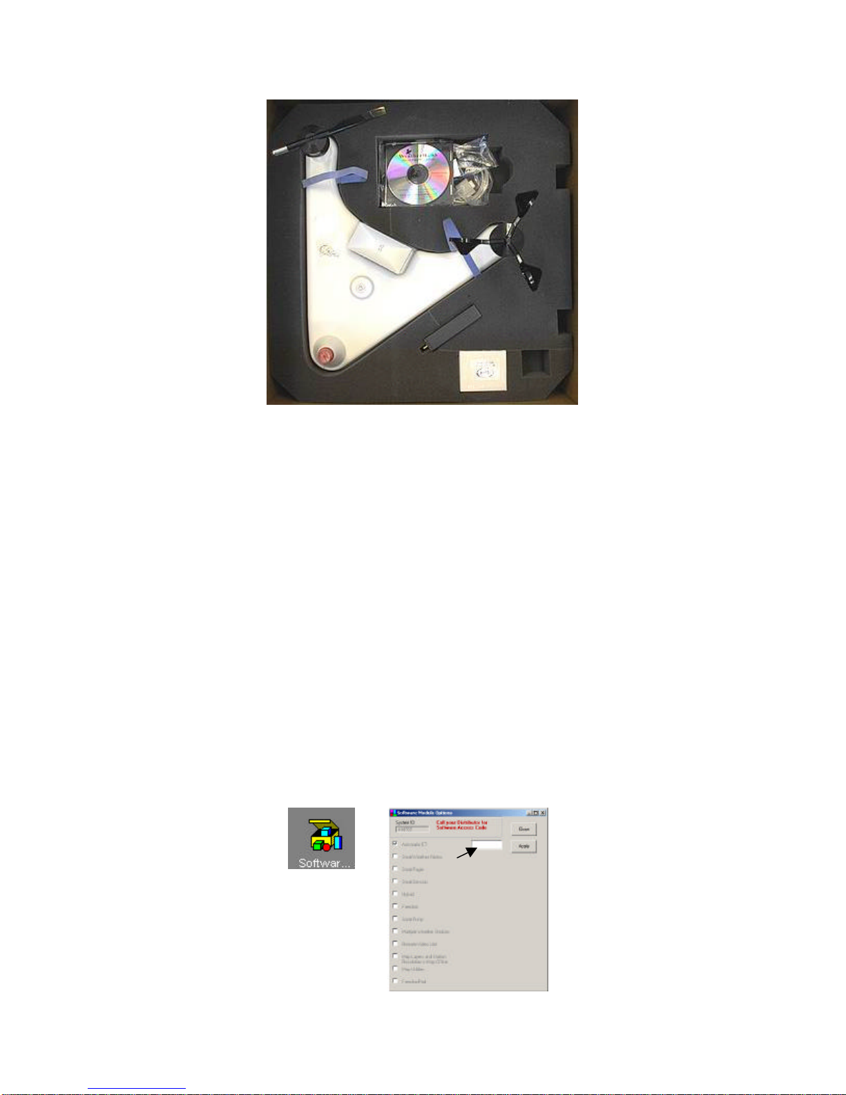
Computer Requirements
•Cirrus, NimbusII, or StratusII central control system with Automatic ET and Multiple Weather
Stations modules. Modules are optional with NimbusII and StratusII central control systems.
Note: The Multiple Weather Stations module is only required if multiple weather stations will be
connected to one central control system.
•Windows 98/2000 or XP Operating System
•Available COM Port

WS PRO LT weather station 4
Weather Station Setup
1. Remove the top foam packing from the box and verify you have all ordered equipment (see Equipment
List). Report missing or damaged equipment to your local Rain Bird distributor before installing your
system.
Equipment List
Models Direct
Connect Direct
Connect
Solar
Powered
Wireless Wireless
Solar
Powered
Wireless
2.4 GHz
Solar
Powered
1. WS PRO LT Weather
Station XXXXX
2. RS-232, serial
communications cable (9-
pin to 9-pin)
XXXXX
3. Two keys XXXXX
4. RF 400-series Spread
Spectrum Radio X X
5. RF415-series Spread
Spectrum Radio X
6. Antenna X X X (whip
antenna)
7. RFXXX AC Adapter XXX
8. Solar Panel X X X
9. Solar Panel Mounting
Hardware X X X
10. RAD Modem for
computer X X
11. RAD modem (in white
box)for weather station X X
12. Cable for connection
between weather station
and RAD modem at
weather station
X X
13. Cable for connection
between RAD modem at
weather station and MSP-
1(9720)
X X
2. Use the lift straps to remove the weather station, since removing the station by lifting on the sensors
may damage the sensors (see Figure 2)

WS PRO LT weather station 5
Figure 2Lift Straps
Note: Avoid resting the weather station on the wind speed and wind direction sensors
3. Connect the serial cable (male connector) to the weather station’s RS-232 port. Be sure to remove dust
cover from the weather station RS-232 port before connecting the cable.
4. Connect the serial cable (female connector) to computer serial COM port
5. Connect power to the weather station (i.e. solar power, user supplied DC power)
6. Turn the key to the ON position.
Weather Station Configuration
1. Request Automatic ET and Multiple Weather Stations module keycodes from Global Service Plan
(GSP) or from your local Rain Bird distributor
2. Start Rain Bird central control software (i.e. Cirrus, NimbusII or StratusII)
3. Enter your keycode by clicking on the Software Modules Options button and entering the keycode(s)
in the corresponding box (see Figure 3)
Figure 3Keycode Dialog Box

WS PRO LT weather station 6
4. Click Apply button
5. Click Close button
6. Click on Today’s ET / Weather Data button
7. Click on Weather Station Configuration button
8. Select weather station from drop down menu (see Figure 4)
Figure 4Weather Station Configuration
9. Select Station Type Rain Bird Turf-CR200
10. Enter latitude and elevation where weather station will be installed
11. Assign port by clicking on Test and Set Port (see Figure 5)
Figure 5Test and Set Port
12. Select weather station
13. Select COM Port (assign to available COM port)
14. Click Assign button
15. Click OK button
16. Enter download time
17. Repeat steps 8-16 for 2nd, 3rd, …, 5th weather stations

WS PRO LT weather station 7
18. Click OK when you have complete the setup
Verify Serial Communication with Weather Station
1. Click on Weather Program button
Note: To access Weather Program from main menu, first select Today’s ET / Weather Data button
2. Click on Monitor Current Data button
3. Monitor the sensor displays. Within a couple of minutes, numerical values should appear on the screen
and indicator lights on the bottom of the weather station, labeled Scan/Receive, will blink every ten
seconds, confirming communication between the weather station and the computer.
4. Synchronize the weather station time to the computer time by clicking on Synchronize WS Time
button
5. Close the monitoring window
6. Disconnect the serial cable from the weather station and place the dust cover back on the serial port.
Continue with Radio Setup for Wireless Weather Station or for direct connect weather stations,
refer to Communication Wiring…instructions.
Radio Setup for Wireless Weather Stations
1. Attach antenna to the radio connector labeled Antenna
2. Connect the serial cable male connector to the radio connector labeled PWR/TW RX
3. Connect the serial cable female connector to a computer serial COM port
4. Plug the RFXXX AC adapter to the RFXXX connector labeled DC Pwr input
5. Plug the other end of the RFXXX AC adapter into a grounded AC wall outlet. The red Pwr/Tx status
light should illuminate
6. Click on Weather Program button
Note: To access Weather Program from main menu, first select Today’s ET / Weather Data button
7. Click on Monitor Current Data button
8. Monitor the sensor displays. Within a couple of minutes, numerical values should appear on the screen
and indicator lights on the bottom of the weather station, labeled Scan/Receive, will blink every ten
seconds, confirming communication between the weather station and the computer.
9. If the radio is not communicating properly, you may be experiencing interference from nearby
equipment such as wireless phones, other spread spectrum radios, or another weather station. Change
the location of the weather station.
10. If your radio is working properly, close the weather software and turn the key to the off position. You
are now ready to install your weather station at a site within ½ mile from the central computer.

WS PRO LT weather station 8
Communication Wiring Setup for Direct Connect Weather Stations
1. Furnish and install a Belden #9883 Direct Burial Type, communication cable between the weather
station and the central control computer (not to exceed 20,000 ft. / 3.8 miles)
Note: The Belden cable should consist of three (3) twisted pairs of wires (20 gauge), a bare copper drain
wire and an aluminum shield. The three (3) twisted pairs shall be color coded as follows: one (1) black and
green pair, one (1) black and red pair, and one (1) black and white pair
At the weather station…
2. Connect the Black (-xmt) and Green (+xmt) pair of wires (of the communication cable) to the Black
and Red wires respectively on the Line end of the first MSP-1
3. Connect the Black and Red wires on the Equip end of the first MSP-1 to the White (-xmt) and Green
(+xmt) wires of the cable (9720) furnished with the weather station
4. Connect the Red (+rcv) and Black (-rcv) pair of wires (of the communication cable) to the Red and
Black wires respectively on the Line end of the second MSP-1
5. Connect the Red and Black wires on the Equip end of the second MSP-1 to the Red (+rcv) and Black (-
rcv) wires of the cable (9720) furnished with the weather station
6. Ground the bare copper drain wire of the Belden cable to the grounding rod using a brass ground wire
clamp.
Note: Do not ground the drain wire at the central end of the cable. Leave it unused.
7. Leave the Black and White pair of wires as spares
8. Connect the other end of the cable (9720) to the Computer connection on the white box (containing
RAD modem)
9. Connect the RS232 end of the second cable (9721) to the RS232 port of the weather station
10. Connect the other end of the cable (9721) to the WX Station connection on the white box
11. Install the white box just below the weather station using furnished U bolt
LINE MSP-1 EQUIP
LINE
MSP-1
EQUIP
Black
Red
Red
Black
Black
Red
Red
Black
White (-xmt)
Green (+xmt)
Red (+rcv)
Black (-rcv)
Black (-xmt)
Green (+xmt)
Red (+rcv)
Black (-rcv)
Communication Wire
from Central Communication Wire at
Weather Station

WS PRO LT weather station 9
At the computer…
12. Connect the black (-xmt) wire to the (-xmt) port of the RAD modem furnished with the weather
station.Use a small screw driver to open the hole, insert the wire and then tighten with the screw driver
13. Continue with the green (+xmt), red (+rcv) and black (-rcv) wires respectively
14. Connect the RAD modem to a COM port on your computer (it might be necessary to use a 9 to 25 pin
adapter)
Installation Procedure
1. Mount a mast/pole 1.25” OD and 8 to 10 feet (312 cm) high on cement base.
2. Place your weather station assembly on top of the mast/pole with the base firmly seated on the top
edge of the mast/pole of (see Figure 6)
3. Loosely tighten the U-bolt nuts so that the weather station is stable but can be rotated on the mast/pole
(Figure 7).
Figure 6Installation
at Pole
Figure 7U-Bolt Nuts

WS PRO LT weather station 10
4. As a reference, use a compass and rotate the weather station assembly until the reference line on the
wind direction sensor is aligned with the Magnetic North (see Figure 8).
5. Firmly tighten the U-Bolt nuts
6. Confirm the weather station is level by viewing the bull’s level on top of the weather station (see
Figure 9). Minor adjustments can be made by placing shims between the weather station base and the
top of the pole.
7. Connect the power source that will recharge the internal sealed rechargeable battery. For Solar
Powered weather stations, follow instructions below.
8. Remove the red cap from the solar radiation sensor (Figure 10).
Bull
’
s
level
Figure 9Bull's Level on top
of the weather station
N
N
Figure 8Wind Direction Alignment
Figure 10 Solar Radiation
Sensor

WS PRO LT weather station 11
9. Properly ground the weather station by connecting a #14 gauge wire to the earth ground lug located on
the base of the weather station. Refer to Grounding Recommendations document D31910 for
grounding recommendations.
10. Refer to Communication Wiring for direct connect weather stations.
11. Turn the key to the ON position and return to the computer site to confirm the weather station is
working properly.
Solar Panel Installation
The solar panel recharges the weather station internal battery. It has a 72 sq.inch surface area and
produces 5 watts, at a peak of 17.1 volts.
Figure 11 5W Solar Panel
1. Place the solar panel on the mast below the station to the maximum distance allowed by the
solar panel cable.
2. Loosely tighten the U-bolt so that the solar panel is stable but can be rotated on the mast or pole.
3. Use a compass to properly align the solar panel. If your site is in the northern hemisphere, the
glass surface of the panel should face south. If your site is in the southern hemisphere, the glass
surface of the panel should face north.
4. Connect the cable to the weather station connector labeled Solar Panel
5. Tighten the thumb screw and the U-bolt


Table of contents
Other Rain Bird Weather Station manuals
Popular Weather Station manuals by other brands

Thies CLIMA
Thies CLIMA 5.4033.35.Series Instructions for use

Oregon Scientific
Oregon Scientific WMR500 user manual

La Crosse Technology
La Crosse Technology WS-7095U instruction manual

Lutron Electronics
Lutron Electronics PHB-318 Operation manual

Levenhuk
Levenhuk Discovery Report WA40 quick start guide

Discovery Channel
Discovery Channel Weathertech FX6000 manual