Rainbow RCC 100 User manual

RCC 100 – Manual

Congratulations on choosing a Rainbow Colour Changers product! We thank you for your custom.
Please note that this product has been designed and made with total quality to ensure excellent
performance and best meet your expectations and requirements.
It is essential to know the information and comply with the instructions given in this manual in order
to ensure the fitting is installed, used and serviced correctly and safely.
Carefully read this instruction manual in its entirety and keep it safe
for future reference! Please hand this manual over if you sell or give this
product to somebody else.
General
Rainbow Colour Changers products are intended for professional use and should only be used by
qualified personnel or under their supervision.
Follow all cautions and warnings indicated on the unit.
After unpacking this product, please check if the device is intact. If this is not the case, please
contact the support service.
Rainbow Colour Changers
An der Talle 26-28
D-33102 Paderborn, Germany
Phone: +49 (0)52 51/14 092-28
Fax: +49 (0)52 51/14 092-90
Installation
Make sure all parts for fixing the colour changer are correct.
Make sure the fixture is stable before positioning the Colour Changer.
Do not fix this device on or near flammable surfaces.
Usage
This product is designed for indoor use only. For the fitting to operate well and reliably, it should
not be used in humid environments. The ambient temperature should not exceed 40°C (104°F) or
fall below 0°C (32°F).
Avoid any liquids or metallic items entering the unit.
Ensure adequate ventilation and do not block or cover any ventilation slots in the device – they
guarantee the reliable functioning of the unit and protect it against overheating.
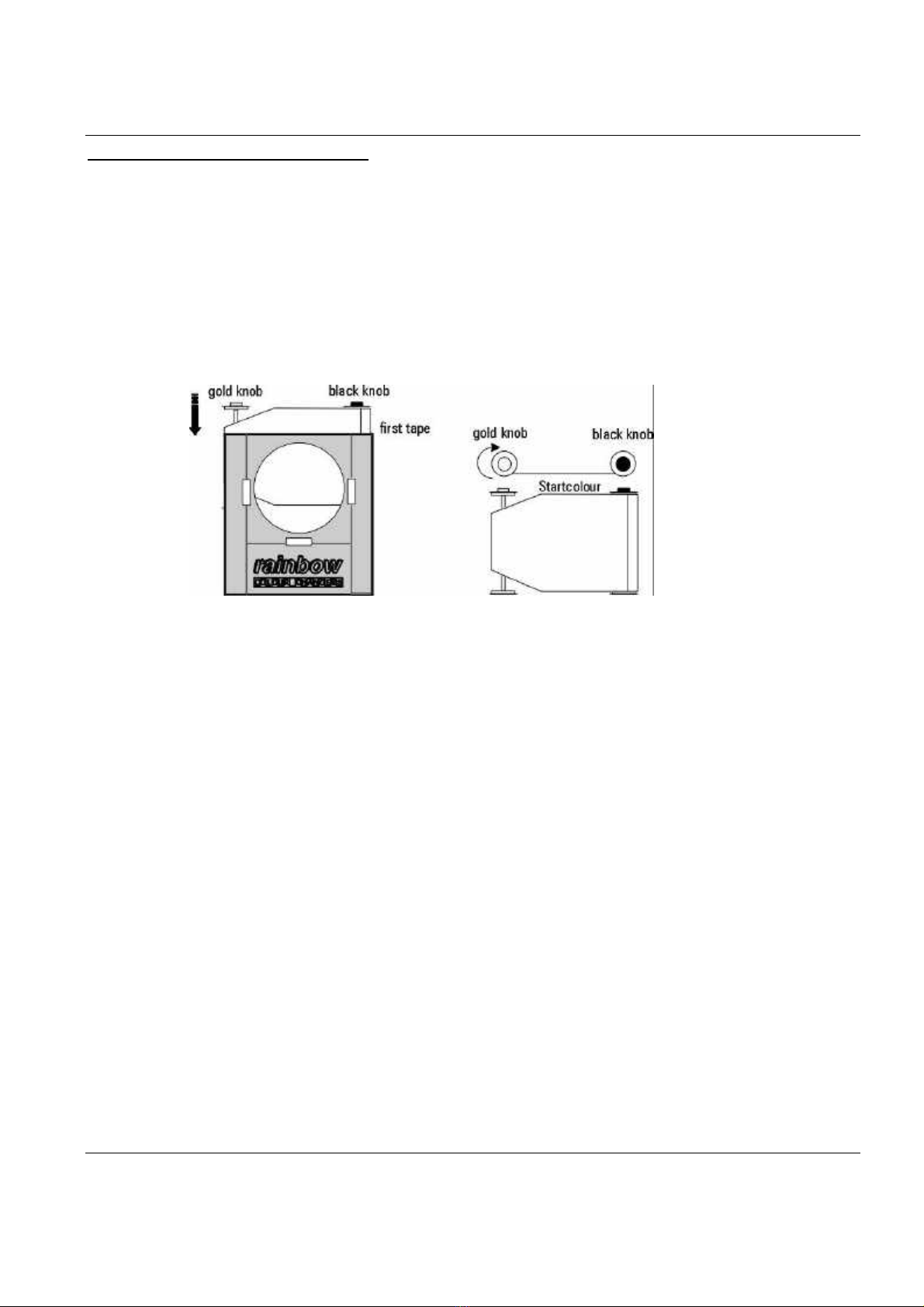
The scroller may only be used in its standard position, which is +/- 60° from horizontal.
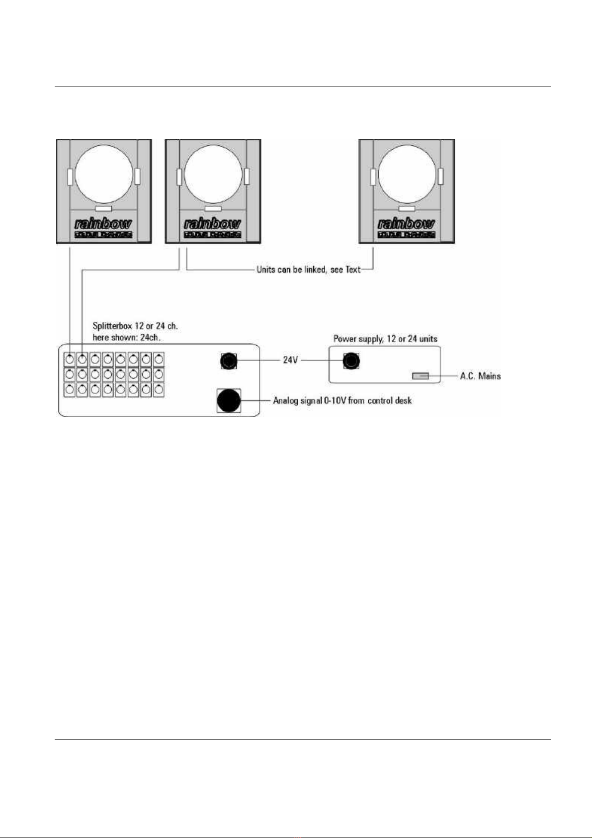
The colour changer may only be put into operation with original Rainbow Colour Changer power
supply units (PSU).
Check that the mains frequency and voltage correspond to those for which the PSU is designed as
given on the surface label of the PSU. Refer to the manual about the max. amount of scrollers to be
connected
Maintenance
All service work should be exclusively performed by qualified personnel.
Do not dismantle the scroller or modify it yourself.
Before starting any maintenance work or cleaning the scroller, remove the power from the PSU.
The surface of the device may heat up due to the luminaire used. Please let the scroller cool down
before touching it.
Rainbow Colour Changers GmbH disclaims all liability for damage to the fitting or to other property or
persons deriving from installation, use and maintenance that have not been carried out in conformity
with this instructions manual, which must always accompany the fitting.
Rainbow Colour Changers GmbH reserves the right to modify the characteristics stated in this
instructions manual at any time and without prior notice.

System introduction
Controlling the Rainbow scrollers
The Rainbow scrollers are controlled with a 0-10V Analog signal or a DMX512 digital
signal. DMX signal can only be used if the DMX option card has been fitted. The DMX
option card can be fitted at any time by your local dealer, and will still allow Analog
operation. The Analog and the Digital systems are treated seperately in this manual. There
are great advantages in using a digital system. The units can be linked and addressed
seperately, making rigging easy. The speed of a unit is directly proportional to the speed of
your control signal.
Calibrating
Contrary to most other scrollers on the market, Rainbow scrollers will remain in position at
loss of power. They will not require any form of startup process (Most other scrollers will
”learn” the Gel string at startup by running through all colours and ”remembering” the
tabs. They will also ”forget” the tabs at loss of power. This means trat they will have to run
through the Gel string after a loss of power to function properly. This procedure can take
up to 30 seconds. The Rainbow Colour Changer will find it´s position according to the
control signal as sson as it´s powered up).
This is due to the fact, trat they are run with a DC motor together with a feedback
potentiometer. Another advantage of this construction is trat you are able to position
anywhere along the Gel string and at any speed.
Mounting on instuments
There are diffrent mounting plates for mounting the units to diffrent lanterns. The
maximum aperture of the PAR scroller is 192 mm. It can be mounted to work in any
position.
Power supplies
There are Power supplies for 12 or 24 units. The power is fed to the splitter box and
distributed from there to each unit in the same as the control signal. The power supply can
be fitted with a G clamp to be mounted in the truss. The power supply is a short circuit
proof switched mode construction which allows AC mains to alter between 200/260 V or
100/130 V, (factory setting).
Splitterbox
The splitterboxes differ depending on it you are running an Analog or a Digital system. The
same power supply is used in both cases. Each type is described seperately in this manual.
General for all splitterboxes is an input for the control signal, another input for 24 V from
the power supply and several output conectors to the scrollers. The splitterboxes can be
fitted with a G- clamp to be mounted in the truss.

System introduction
Gel rolls
The gel roll construction of the units consists of two spools, one with a gold knob and the
other with a black knob. The spool with a gold knob has a build-in spring which takes care
of tensioning the gels. You can easily prepare, mount and install gel rolls following the
instructions in this manual. Changing gel rolls in a unit is done without need of any tools in
amatter of minutes.
The units are factory trimmed foe a working range of 11 colours, or a total filter lenght of
3080 mm plus a leader and a tail of 320 mm each. The standard number of colours is
eleven because it gives one colour for each 10% control signal input to a unit. You are free
to change the lenght of each colour within the total lenght of the colour string without
need for readjusting the unit. If however you wish to change the total lenght of the colour
string, you will have to re-trim the unit with the trim pot in the back of the unit. This
described later in this manual. A unit can be trimmed for 2-16 colours.
If the colour string is shorter than the range it will be ripped of the spool and if it´s too
long you won´t be able to reach the end colours.
Cooling
To lenghten the life span of the gels we have fitted each unit with an internal fan. The fan
can run at two speeds, high or low. This is set with the fan switch on each scroller. Running
on low speed will shorten the life span of the gel string and should be used only when
extremely quiet operation is needed.
Rigging a Rainbow scroller system
The units are mounted on the lighting instruments of your choice. You can mount the
splitterbox and the power unit (1 per 24 units) in the truss with G-clamps. The power is fed
into the splitterbox and distributed from there to each unit. The distribution and the
splitterbox depend on if your system is controlled digitally (DMX512) or Analog (0-10V).
The cables used for distribution to the units are of the same sort in both systems.
Standeard four pin XLR connectors are used. (seepage17 on Power/control cables).
On the base of each unit there are three LED indicators. The red LED indicates, trat power
is on. The yellow LED shows the input signal to the unit. The green LED indicates, trat the
incoming DMX data is correct. If the red LED is flashing, it indicates ”auto motor shut off” is
activated – the scroller for some reason cannot reach it´s position.

Cutting and mounting a gel string
Drawing:
Step 1
Use cutting templates provided by us or make your own as described above.
Use a razor or a sharp knife to cut the filters.
Step 2
Align filters correctly, no overlapping.
Step 3
Tape only on one side. Cut ends of exessive joining tape. Use only high temperature tape
Scotch 3M. Avaible from us.
A gel roll can have 2-16 colours and will always consist of two leaders measuring as
above and filters inbetween measuring 280 x 208 mm. You can vary the size of the gels
but the maximum total length trat a scroller can be trimmed for is 4480 mm.
Hint1:
When preparing spare rolls, take care to store rolls with the joining tape outwards and the
end colour outward. It is then easier to mount the gel string on the spool with the black
knob as described further on.
Hint2:
Dark coloured filters will react to heat and become deformed earlier than lighter coloured
filters. This can effect the positioning of the other filters if the darker filters are placed as
the last filters, thus being rolled up most of the time. Therefore it is a good idea to place
darker filters closer to the start colour than to the end colour.

Mounting gels on rolls
Drawing:
Step 1:
Attach the start and end colours to the midpart of the rolls with the heat resistant tape
(100 mm). Make sure trat the joining tape is on the outside of the gels when you wind up
the roll as described in Step 2.
Step 2:
Make sure trat the gel string is wound up counter clockwise on the roll with the black knob
(seen from the top). This makes it easier for you when you are mounting and synchronizing
the roll in the scroller.
Take care not to force the gold knob counter clockwise when tensioning the gel roll. If not
you might break the tensioning spring.

Mounting gel rolls in scroller
To trim the zero position of the gel roll in the scroller, the scroller has to be connected to a
control desk.
Step 1:
Make sure trat the signal from the control desk to the scroller is at zero level. The yellow
LED indicating input to the scroller should be off.
Drawing:
Step 2:
Make sure trat the gel string is wound up on the spool with the black knob. The tape
should join of the first filter should be aligned to the spool with the black knob as in the
figure.
Step 3:
Fit the roll with the black knob into the scroller and make sure it has locked around the
socket pin inside the scroller. Then turmn the gold knob clockwise to tension the gel string.
If your gel string has got other than 11 colours, or your control desk doesn´t give exact
values you now will have to calibrate your scroller.

Calibrating
The scrollers are factory calibrated for a gel string of 11 colours. If your gel string has other
than 11 colours, or your control desk doesn´t give exact values you now will have to
calibrate your scroller.
Drawing:
Step 1:
Use a small screwdriver at the trimpot. ”range” on the back of the scroller and turn this
pot. fully counter clockwise before power on. This pot can change the trimming range
between 2 and 16 colours, therefore you might have perform up to 15 turns to set it fully
to it´s end position, you will not feel the ends apart from a ”small klicking” sound.
Drawing
Step 2:
Set the control desk to 100%. Use the trimm pot. to trim the end colour. Your scroller is
trimmed when 100% on the control desk corresponds to the end colour. Repeat this
trimming procedure for each unit. Trimming clockwise will prolong the trimming range.

Analog system
Drawing
General:
In an Analog system 0-10V standard output signal from any type of control desk is fed into
the splitterbox together with the 24 V DC from the power supply unit. The power/control
signal is distributed from the splitterbox to a maximum of 12 or 24 individual scrollers.
Up to 6 scrollers can be linked to the same output if cable lengths do not exeed 10 meters,
but you can never exeed the capacity of the power supply unit. To power more than 24
units from one splitterbox you will have to use the option of connecting two 24 unit power
supplies in parallel.
As any analogically controlled moving unit, the Rainbow Colour Changer analog system
requires a stable analog control signal. Any variations in the signal will be noticed more or
less in the positioning of the scroller.
Hint:
If your analog control signal is passing any other equipment connected to mains (dimmers
for example), make sure trat the same mains earth is used also for this equipment. If
possible, check trat your scroller system is ”floating” against the mains earth before you
power up for the first time. This is done with an Ohm – Meter measuring between the
signal ground and the mains ground. There should be no connection between these two
whatsoever, which is indicated by infinity ohm´s on the Ohm – Meter.

DMX System
Drawing:
General:
The DMX signal from a control desk is fed into the splitterbox together with the 24V DC
from the power supply unit. The power/control signal link is distributed from the splitterbox
in 4 paralell outputs. Each output can support up to 12 individual scrollers. This makes a
possible total of 48 scrollers/splitterbox. Make sure trat you connect the return cable from
the last unit to the splitterbox to ensure reliable functioning. Each scroller is given an
address with the switches at the back of the scroller. T power more than 24 units from one
splitterbox, you will have to use the option of connecting two 24 unit power supplies in
parallel.
Return connection:
The return connection from the last scroller back to the splitterbox ensures sufficeint power
for the scrollers within the loop. It also serves the the purpose of a correct termination for
the DMX signal. You can replace the return cable with a terminator plug in the last scroller
of each output – providing the speed of the last scroller isn´t affected by not having a
return cable. A terminator plug is made of a male 4-pin XLR connector with a 100Ohm
resistor between pin 2&3.
Analog desk – DMX system:
If you want to run the scrollers in DMX mode from a control desk with an Analog output,
you will need an Analog to Digital converter. DMX gives easy patching of channels to the
scrollers.

Power Cable 24 V
Cable lengths:
Use ordinary 3 core rubber sheathed AC cable.
Cable size Cable lengths Voltage drop at full load*
1,5 mm²/16AWG 5 meters/15 feet 1V
15 meters/45 feet 4V
2,5 mm²/12AWG 8 meters/24 feet 1V
25 meters/75 feet 4V
4,0 mm²/10AWG 12 meters/36 feet 1V
40 meters/120 feet 4V
6,0 mm²/8AWG 18 meters/55 feet 1V
60 meters/180 feet 4V
•Voltage drop does not affect positioning, just the maximum speed.
Neutrik NL4 24V Connector
This is how you connect the Neutrik 24V connector:

Power supply for 12 or 24 units
The power supplies come in two sizes; for 12 or for 24 units. They can be fitted with a G-
clamp to be mounted in the truss.
PSU 24 units PSU 12 units
Heigth: 85mm/3,5”85mm/3,5”
Width: 215mm/8,25”215mm/8,25”
Depth: 330mm/13”330mm/13”
Weight: 3,8kg/8,5lbs 3,2kg/7lbs
Fuse: 5AT 6,3x32mm 4AT 6,3x32mm
Current: 230V:2,5A 230V:1,6A
115V:4,4A 115V:2,7A
Caution: The PSU must be connected to an A.C mains outlet ith mains
earth. Do not connect to a dimmer circuit.
Power: The power supply is a light weight switched mode construction
allowing mains to alter between 220-240V, or 110-120V, +/-
10% depending on the factory setup.
Parallel option: Two power supplies can be connected in parallel via the ”parallel
option” connector. This enables you to connect the max. amount
of scrollers possible to a DMX splitterbox and power them on a
single line. The option connector should not be used for other
purposes.

DMX 512 digital splitter box:
The DMX splitter box is fully buffered and re-amplifies the signal. Always connect a return
cable from the last scroller from each output to the return sockets. This improves current
feeding and DMX transmission, see page 10.
Signal Connectors:
DMX 512 Connector Power/Control cable
XLR-5p connector XLR-4p Female connector
Pin 1: Signal earth Pin 1: 24V -
Pin 2: Data –Pin 2: Data -
Pin 3: Data + Pin 3: Data +
Pin 4: 24V +
24V connector:
Neutrik NL4 connector
Pin 1- : 24V –
Pin 1+ : 24V +
Pin 2- : Mains earth (for DMX use)

DMX spiltterbox Earth selector:
Variations in the signal earth may cause problems in a system. Therefore we have
incorporated an earth selector in the DMX splitterbox, so you can seperate the earth in the
scroller system from the rest of your DMX line and the equipment connected to it. We
recommend trat you always try to seperate the signal earth of the scrollers from any other
equipment by selective use of this selector switch as described below.
There are two positions for the earth selector: LOCAL and COMMON.
Local:
The incomming signal earth will end in this splitterbox. A new earth point is created for the
DMX signal at the outputs of this splitterbox on the DMX line. If the DMX line continues
from the last splitterbox to other equipment, then set this last splitterbox to local also.
Common:
The common position will continue the incomming earth. The POWER LED on the front of
the splitterbox will indicate common earthing by flashing. This position is used for all
splitterboxes except the first and last if several are used.

Analog splitterboxes 12 or 24:
The analog splitterbox comes in two sizes: 12 channels and 24 channels. The amount of
scrollers trat can be linked to a box depends on the capacity of the power supply.
12 channels 24 channels
Heigth: 165mm/6,5”165mm/6,5”
Width: 230mm/9”230mm/9”
Depth: 60mm/2,5”60mm/2,5”
Weight: 2,2kg/5lbs 3,3kg/7,25lbs
Current: 0,0A 0,0A
Analog signal connector
The analog splitterboxes are not fitted with a standard input connector for the control
signal. The connector type is offered at request and is fitted where shown. Among the
available connectors are Socapex, AVAB KPT& D-sub 25.
Power / Control cable
Pin 1: 24V -
Pin 2: Data -
Pin 3: Data +
Pin 4: 24V +
24V connector:
Neutrik NL4 connector
Pin 1- : 24V –
Pin 1+ : 24V +
Pin 2- : Mains earth (for DMX use)

PAR scroller:
The PAR scroller can operate in analog or DMX mode. The three LED´s on the bottom of
each unit will indicate power and running status according to the text figure below.
DMX address:
Each unit in a DMX system has to be given an address. If several units have the same
address, they will respond simultaneously to incoming signals.
Analog or DMX selector:
This switch decides if the scroller works in Analog or DMX mode.
Fan:
This selector allows two fan speeds for optimum noise/cooling setting.
Range:
This is where you trim the gel range for the unit. See calibrating on page 8.

General:
It is essential that all custom made cables confirm to our specifications.
The gauge must be at least the rated one.
Cables should be screened and must not be connected to the case of the connectors. A
screen touching the case of the connector is always hazadous to the function of both
analog or digital scroller systems, because it creates an unwanted earthloop.
Insulate each pin with some kind of tubing. Any shortcircuit within the connector will ruin
the functioning of the system and might even distroy other components in the equipment.
In a DMX system a shortcircuit between pin 4 and pins 2 or 3 will destroy the output line
driver. This is because 24V will be fed back to the output of the linedriver circuit.

Safety in the system:
We have incorporated several safety features in each RCC. The following can be good to
know.
Internal fuse:
An internal reversible fuse in each scroller will protect the rest of your system from
breaking down in case of major problems in a single unit. This fuse will automatically be
reset at no overload.
Line input:
The line input of the scrollers will withstand any voltage within +/- 24V relative to the
earth (pin1) without tearing the gel string.
Feedback pot:
The feedback pot inside each scroller has no end stops and will therefore not be broken by
forcing past the zero or end position.
Motor:
The motor is protected from overload and will not burn.
Auto motor shut off circuit:
The auto motor shut off circuit in each scroller will stop the RCC if for any reason the
position cannot be reached within 10 seconds. This could be caused by a broken cable,
locked rolls or other mechanical or electrical disturbance to the servo system. This ensures
trat a scroller never will run out of control. The scroller resets at power down aund up.
DMX card:
The DMX card is equipped with a watchdog trat will reset automaticcally at any signal
disturbance.

Troubleshooting a system:
Here are some hints on troubleshooting a RCC scroller system. Remember trat the
guarantee will be void if unauthorized personell opens housing of the equipment.
All systems: Scrollers will not move at all
If motors receive less than 18V, they will automatically be shut off.
•Check the 24V LED on the PSU (Power Supply Unit) If it is off, the PSU is delivering less
than 18V.
•The lamp in the PSU mains switch indicates trat there is power to the PSU. Check fuses
at PSU back.
•Check POWER LED on the bottom of the RCC units. It will not be lit if less than 18V
reaches the unit.
•If PSU is okay and RCC POWER LED is off, check Power/control cable for short circuits
or loose leads.
•If RCC POWER LED flashes, it means trat the Auto motor shut off function is activated.
Check the scroller and gel roll. Reset by power off-on.
•In an emergency situation, you can substitute a faulty PSU with two 12V car batteries
connected in serial.
Digital system: scrollers are juddering
A corrupt DMX signal can create a juddering effect in the scrollers.
•Make sure the return connection from the last scroller is connected. If not, make sure
there is a terminator plug consists of a 100 ohm resistor between pin 2&3 in a male 4
pin XLR connector.
•If several scrollers are linked to an output, try disconnecting one or two and see if the
fault disappears.
•It might be an earth problem. See page 14 about the earth selector in the DMX
splitterbox.
•If an A/D converter is used to let a control desk with analog output control a digital
scroller system, it may cause this problem. A/D converters often create something
called bit jittering within the DMX signal due to ”noise” in the incomming analog
signal. This jittering may result in a position variation from 13 mm to half a colour in a
scroller.
Make sure trat the A/D converter is placed as close to the control desk as possible. Use
short screened cables for the analog signals to prevent noise pickup. There are converters
on the market trat take care of this problem better than others. Do not hesitate to contact
us if you run into this specific problem.

Troubleshooting:
Digital system: Speed diffrence between first and last scrollers:
•Connect the return cable from the last scroller instead of using a terminator plug.
Digital system: Scrollers stay in position but will not move:
•If DMX data is faulty or missing, the RCC will stay in it´s position until new DMX data is
received.
•Check DMX transmission cables and control desk.
Analog system: Scrollers are juddering, chasing or moving to sound:
•Check the analog control signal with an oszilloscope to see trat it is stable.
•Check trat signal earth is ”floating” against mains earth and trussing. Like this:
Disconnect the signal multicable at the control desk. Measure with an ohm meter
between signal earth in the multicable and mains earth, trussing etc. There should be
no connection al all between signal earth and the rest of the equipment. If there is,
check cables and connectors to see if screen is touching connectors or broken.
•Do not power two splitterboxes from one PSU. This will create earthloops trat mostly
cause problems.
•In scrollers version 2 and up (see serial numbers below), you may need a link in the
splitterbox between signal earth and minus 24V. There is a simple way to achieve this:
Just connect pin 1 and 2 in a male XLR 4 pin connector and insert it into a free output
in the analog splitterbox.
Serial numbers RCCversion 2 and up
1658 PAR scrollers
43 Lightcurtain 9x PAR56
8Lightcurtain 6x PAR56
56 2kw-5kw Fresnel
138 Thomas 8 lite
Analog system: Scroller goes to zero position:
•If analog control signal is missing, the scrollers will return to their zero position. There is
no position memory in the analog mode.
Table of contents