RainMaker FLUIDLOGIC User manual

DESIGNEDINCALIFORNIA/PATENTFLUIDLOGICCOM/PATENTS•RAINMAKERSOLUTIONSINCELSEGUNDOCA
FLUIDLOGICCOMANDTHECIRCUMFERENTIALBANDSAROUNDTHEFLUIDLOGICCOMQUICKCONNECTSARE
TRADEMARKSOFRAINMAKERSOLUTIONSINC•MADEINUSA•FLUIDLOGICCOM
• HASSLEFREEHYDRATIONATSPEED
Steering wheel mounted button allows you to hydrate at anytime,
anywhere while doing battle.
• HYDRATIONDELIVEREDEFFORTLESSLYTOYOURLIPS
No more reaching for a hose and sucking to get the fluid flowing. Those
days are over. Touch the button and fluid flows freely immediately and
effortlessly.
• FULLYPROGRAMMABLETOHOWYOULIKETODRINK
Program how much fluid is delivered with a single press, and how oen the
system reminds you to drink and at what strength the dose is delivered.
• EXPANDABLECONTROLOFTHESYSTEM
Manage multiple FLUIDLOGIC™Systems and customize user profiles
inside the FLUIDLOGIC™ App.
• PACETHERACEANDFINISHSTRONG
Program the system to deliver hydration on schedule, not over-drink and
ensure you have fluid throughout the race.
• FASTERANDEASIERRECOVERY
Consistent hydration is less taxing on the body. Our research shows that
small frequent doses, hydrates more effectively. Keeping the body from
overdosing and taxing the system. Recovery is more efficient and faster
overall.
From the team that brought you MAGLOCK®, the magnetic helmet connection for
forced-air systems. Introducing FLUIDLOGIC™, the world’s first, fully programmable,
high-tech and hassle-free hydration systems for motorsports applications.
With more than 3 years of testing and development, FLUIDLOGIC™ has been proven in
the toughest motorsports events in the world. From the Baja 1000, to the Brickyard of
Indy, our product development team has worked tirelessly to provide a system that has
proven itself to keep drivers hydrated at speed in the heat of battle.
On-road, off-road, open-wheel, recreational and more! No matter if you’re a professional
or an amateur driver you will enjoy the ease of use that FLUIDLOGIC™ offers.
With the simple touch of the microbutton FLUIDLOGIC™ delivers fresh fluid, to
the users lips, with programmed doses, at the desired strength. An LED light on the
Microbutton can be programmed by the user to flash at a predetermined time to
reminder the user to hydrate.
Magnetic connections, utilizing MAGLOCK® technology, allow Drivers to quickly and
safely attach hydration to their Helmets for Forced-air or open-wheel applications. In
the case of a, “Hot Extract”, when every second counts, drivers and safety personnel
can easily remove our system for the driver to exit the vehicle as quickly and safely as
possible. The fear of further injury is virtually eliminated.
The future of hydration is here with FLUIDLOGIC™ in your vehicle. Welcome to the
Hydration Nation!
INSTALLATION INSTRUCTIONS • PRODUCT SAFETY & LEGAL DISCLAIMER
DESIGNEDINCALIFORNIA/PATENTFLUIDLOGICCOM/PATENTS•RAINMAKERSOLUTIONSINCELSEGUNDOCA
FLUIDLOGICCOMANDTHECIRCUMFERENTIALBANDSAROUNDTHEFLUIDLOGICCOMQUICKCONNECTSARE
TRADEMARKSOFRAINMAKERSOLUTIONSINC•MADEINUSA•FLUIDLOGICCOM
IMPORTANT READ ALL INSTRUCTIONS CAREFULLY BEFORE INSTALLING, FAILURE TO DO SO MAY CAUSE PERSONAL INJURY OR DAMAGE TO PRODUCT AND/OR PROPERTY.
INJURY HAZARD
• Please complete a shop and tool inspection prior to beginning the installation.
• Always make sure you have a clean, dry and well lit work area.
• Always remove jewelry, loose fitting clothing and wear protective gloves and eye
protection.
• Always use extreme caution when jacking or raising a vehicle for work. Set the
emergency brake and use tire/wheel blocks and jack stands. Refer to the vehicle
manufacturer hand book. Utilize the vehicle manufacturer’s designated liing points.
• Always use appropriate and adequate care in liing parts during disassembly and
installation. Seek help in liing heavy or large items into place. Utilize jack stands and or
liing devices when liing the vehicle.
• Always ensure products are secure during disassembly and installation.
• Always wear eye protection and take steps to protect any exposed skin during the
installations. Drilling, cutting and grinding plastic and metal may create flying particles
that can cause injury.
• Always use extreme caution when drilling, cutting and or grinding on a vehicle.
Thoroughly inspect the area to be drilled, on both sides of material, prior to
modification and relocate any objects that may become damaged.
• Always assemble and tighten all fasteners per the installation instructions.
• Always route electrical cables carefully. Avoid moving parts, parts that may become
hot and rough, or sharp edges.
• Always insulate and protect all exposed wiring and electrical connections.
• Review the product packaging and contents prior to beginning the installation. Take
care when opening the packaging and removing items. If a return is necessary it is best
to return the product in its original packaging if possible.
• This instruction guide is provided as a GENERAL installation guide, some vehicles vary
dimensionally and may require additional steps. If at any time you have any concerns
about your ability to install this product please reach out to a qualified installation
specialist to provide professional installation of this product.
• Test fit the product on the vehicle prior to any third party modifications and/or
finishing. The manufacturer and/or retailer do not accept responsibility for third party
charges, labor and/or third part replacement modifications. Some modifications may
void the factory warranty.
• Exercise due-diligence when installing this product. The manufacturer and retailers
of this product do not accept any responsibility for vehicle damage or personal injury
resulting from the installation of this product. Careless installation and operation can
result in serious injury or equipment damage.
• This product is for general off-highway use. All liability for installation and use rests
with the owner/operator.
• INSTALLER: Once installation is complete, please return this guide along with other
documentation included in this product back to the consumer for future reference. The
manufacturer/retailers of this product do not guarantee this particular version will be
available at a later date.
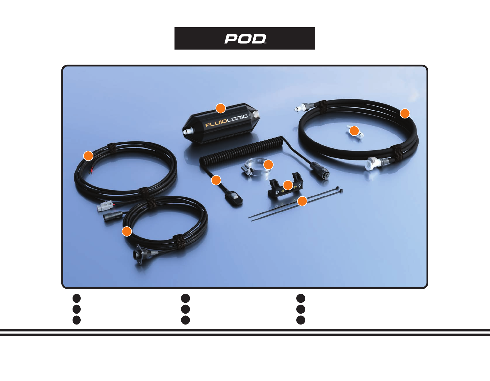
INVENTORY LIST
B
C
A
D
E
F
H
G
THE POD
12 VOLT CABLE
POD TO DASH CABLE
A
B
C
MALE CPC CONNECTOR
FLUID LINE W/CPC CONNECTORS
MICROBUTTON ZIP TIES
G
H
I
MICROBUTTON CABLE
ROLL BAR HOSE CLAMP
ROLL BAR MOUNT
D
E
F
I
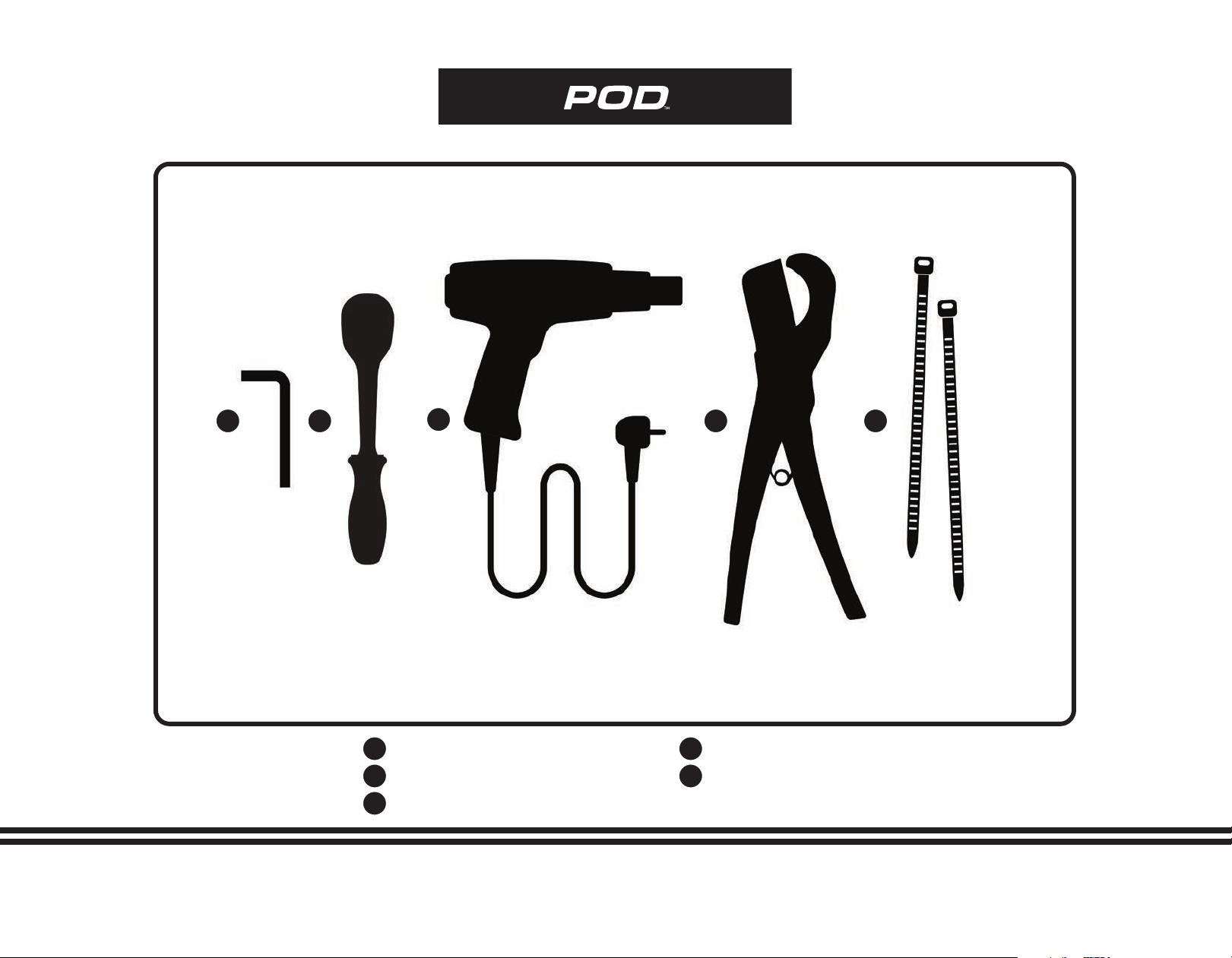
TOOLS NEEDED
BC
ADE
3MM ALLEN WRENCH
5/16” SOCKET
HEAT GUN
A
B
C
HOSE CUTTER
ZIP TIES
D
E
5/16 ”
Locate the current location of your existing fluid
reservoir. Bladders, insulated coolers or insulated
bottles are all suitable devices. FluidLogic does
not include a container with the kit as each
vehicle requires its own suitable size and location
for the reservoir.
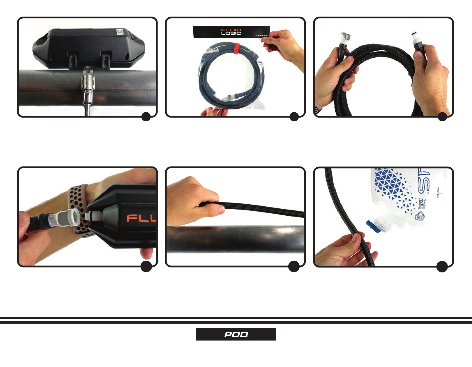
Take the Pod and install the Roll Bar Mount onto
the Pod aer identifying the correct orientation.
The water flows from the “F” of FluidLogic™logo
toward the “C” and outward to the user. Note, the
Roll Bar Mount can be placed on the top or the
bottom of the Pod depending on your preference.
123
Using a 3mm Hex Key, install the Roll Bar Mount
to the Pod. Please note, that the Mount also has
threaded inserts so that it can be mounted to a
plate or bulkhead in the vehicle.
Locate the Roll Bar Hose Clamp in the Pod to
Dash Cable Bag. Fully open the included Roll Bar
Hose Clamp using a 5/16” socket or driver.
Pass the Roll Bar Hose Clamp through the Roll
Bar Mount and the Pod.
456
Select a safe location in the vehicle that is clear of
impacts, foreign debris, heat, exhaust fumes etc.
INSTALLATION INSTRUCTIONS • 4
INSTALLATION INSTRUCTIONS • 5
Using a 5/16” socket or driver, tighten the Hose
Clamp around the bar and securely mount the
Pod inside the vehicle.
Locate the 1/4” Fluid Line.
789
Disconnect the CPC Connectors and take note
of the male and female connectors and unwind
the Fluid Line.
Connect the female connector to the inlet side
of the Pod.
Once connected run the Fluid Line towards the
fluid reservoir.
11
Give the line plenty of slack to assure that once
connected to the fluid reservoir there is no
restrictions. Measure twice!
12 13

INSTALLATION INSTRUCTIONS • 6
Insert the male CPC Connector into the cut end
of the Fluid Line. Once seated into position, slide
the Heat Shrink over the end of the connection.
Make sure to slide the Heat Shrink half-way onto
the hexagonal CPC Connector end.
Once the Heat Shrink is properly aligned, heat
the material with a heat gun, being careful not to
over-heat the area.
17
Insert the CPC Connector into the Bladder and
locate it in its final storage location.
18 19
Assure the measurements are correct and cut
the Fluid Line. Keep the remaining section
of Fluid Line for use later in the installation.
(Coaxial Section #13). Insure the cut is clean, and
perpendicular to avoid any leaks, this is very
important.
Take the supplied loose male CPC Connector
and prepare to connect it to the fluid reservoir.
14
Slide the supplied Heat Shrink over the cut end
of the Fluid Line.
15 16

INSTALLATION INSTRUCTIONS • 7
Secure the 12 Volt Cable to the vehicle and run it
towards the power source. In this instance, we are
running both the 12 Volt Cable AND the Fluid Line
together for a clean, efficient look. If using Zip Ties, be
sure not to over tighten them as this may inhibit fluid
flow.
Run the 12 Volt Cable to the power source in the
vehicle and connect it to a 10 amp fuse circuit.
24
Locate the Pod to Dash Cable.
25 26
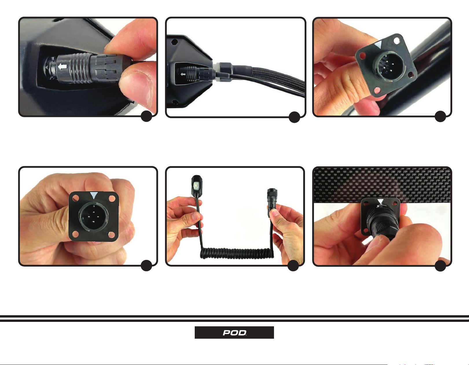
Locate the 12 Volt Cable. Take the installed Gray Deutsch Connector and
insert it into the rear inlet side of the Pod.
21
Make sure that when you insert the Gray Deutsch
Connector you hear a secure, “Click” to assure
that the part is inserted correctly.
22 23
INSTALLATION INSTRUCTIONS • 8
Once the Pod to Dash Cable is run, note the
arrow. Mount the arrow upward so that it is easily
seen by the user.
Locate the Microbutton Cable.
30
Take the connector and align the arrows. Push
and rotate the collar counter-clockwise into the
locking position. Route the Cable to the desired
side of the steering wheel.
31 32
Align the arrow of the connector with the Pod
and carefully connect the two. Once installed
correctly, the connector will “Click” to confirm it
is attached correctly.
Route the Pod to Dash Cable through the vehicle,
working towards the dash, within the vicinity of
the steering wheel.
27
Take the Pod to Dash Cable and mount the dash
end directly to a secure area on or behind the
dash or to the steering column, making sure to
secure the Cable away from any moving parts that
may damage or detach the Cable. An opening of
20mm will assure proper connection.
28 29
INSTALLATION INSTRUCTIONS • 9
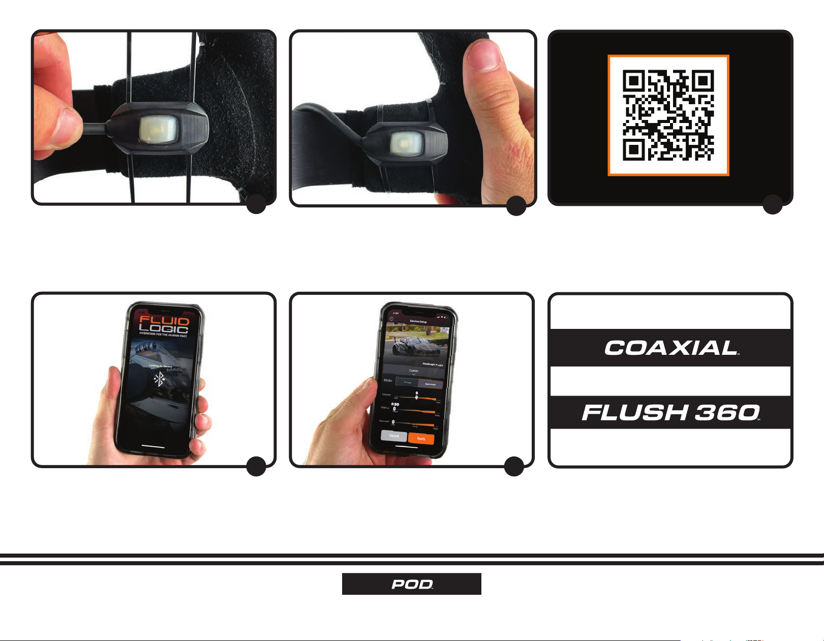
Power the vehicle/Pod and open the FluidLogic™
app to pair the device with your phone. You
should be within a reasonable distance in order to
pair the device successfully, using the QR Code
located on the underside of the Pod packaging
box lid or on the bottom side of the Pod itself.
Once paired, adjust the parameters and test the
pump by pressing the Microbutton. No fluid is
needed to test the system. Once the Microbutton
is pressed, the pump will make an audible noise
indicating it is operating.
36 37
Find a location on the steering wheel face for
the Microbutton. The location should be within
thumbs reach and easily accessible while driving.
Secure the Microbutton using the supplied Zip
Ties to the steering wheel. Cut off the excess Zip
Tie material, rotate the wheel from lock to lock
to assure the Cable does not interfere with the
operation of the vehicle.
33
Download the FluidLogic™application from the
Apple App Store. Scan the above code to do so.
34 35
INSTALLATION INSTRUCTIONS
–OR–
NEXT STEP
INSTALLATION INSTRUCTIONS
This manual suits for next models
1
Table of contents


