Ramsa Ramsa WR-DA7 User manual

SPECIFICATIONS
General
Power requirement : AC 220 – 240 V 50 Hz
Power consumption : 105 W (with options)
Frequency response : 20 Hz - 20 kHz, +1 dB - –2 dB
T.H.D. (total harmonic distortion) : Less than 0.1 % (input = +10 dB/1 kHz, output = +4 dB/RL 600 Ω)
Equivalent input noise : –128 dB (Rs = 150 ΩInput sensitivity = –60 dB typical)
Residual noise : –93 dB typical
Maximum voltage gain : 84 dB: MIC/LINE(1-16) in to BUS out
84 dB: MIC/LINE(1-16) in to MASTER out
84 dB: MIC/LINE(1-16) in to AUX out
Common Mode Rejection Ratio : More than 80 dB (1kHz)
Crosstalk : 90 dB typical (1kHz)
Dynamic Range (Fs = 48kHz, DIN audio filter) : 113 dB typical : DA converter (digital in to analog out)
112 dB typical : AD converter (analog in to digital out)
110 dB typical : AD + DA (analog in to analog out)
AD Converter : 24 bit, 64 times oversampling (input 1 to 16)
20 bit, 64 times oversampling (aux returns 3 to 6)
DA Converter : 24 bit, 64 times oversampling (MASTER, MONITOR A)
24 bit, 128 times oversampling (MONITOR B)
20 bit, 128 times oversampling (aux returns 3 to 6)
Internal signal processing : 32 bit (Dynamic range 192 dB)
Sampling Frequency (Fs) : Internal: 44.1 kHz and 48 kHz
External: 44.1 kHz ± 6 % and 48 kHz ± 6 %
Signal delay : Less than 2.5 ms, MIC/LINE input to MASTER out
Audio Mixer
WR-DA7
ORDER NO. AVS9807114C8
C1998 Matsushita Communication Industrial Co., Ltd.
All rights reserved. Unauthorized copying and
distribution is a violation of law.
The Meter Bridge shown in photo is one of the optional accessories.

This service information is designed for experienced repair technicians only and is not designed for use by the
general public.
It does not contain warnings or cautions to advise non-technical individuals of potential dangers in attempting to
service a product.
Products powered by electricity should be serviced or repaired only by experienced professional technicians. Any
attempt to service or repair the product or products dealt with in this service information by anyone else could
result in serious injury or death.
!WARNING
CAUTION
RISK OF ELECTRIC SHOCK
DO NOT OPEN
CAUTION:
TO REDUCE THE RISK OF ELECTRIC SHOCK,
DO NOT REMOVE COVER (OR BACK). NO USER
SERVICEABLE PARTS INSIDE.
REFER SERVICING TO QUALIFIED SERVICE
PERSONNEL.
This symbol warns the user that uninsulated voltage within
the unit may have sufficient magnitude to cause electric
shock. Therefore, it is dangerous to make any kind of contact
with any inside part of this unit.
This symbol alerts the user that impotant literature concerning
the operation and maintenance of this has been included.
Therefore, it should be read carefully in order to avoid
any problems.
There are special components used in this equipment which are important for safety. These parts are indicated
by the ”Y” mark on the schematic diagram and the replacement parts list. It is essential that these critical
parts should be replaced with manufacturer's specified parts to prevent shock, fire, or other hazards.
Do not modify the original design without permission of manufacture.
IMPORTANT SAFETY NOTICE
Dynamics
Compressor
Threshold : –40 dB - 0 dB (1 dB/step)
Ratio : 1.0, 1.1, 1.3, 1.5, 1.7, 2.0, 2.5, 3.0, 3.5, 4.0, 5.0, 6.0, 8.0, 10, 20, ∞(16 points)
Attack time : 0 ms - 250 ms (1 ms/step)
Release time : 5 ms - 2000 ms (5 ms/step)
Gain : 0 dB - +12 dB (0.5 dB/step)
GateThreshold : –80 dB - –15 dB (1 dB/step)
Attack Time : 0 ms - 250 ms (1 ms/step)
Release time : 5 ms - 2000 ms (5 ms/step)
Expander
Threshold : –80dB - –15dB (1dB/step)
Ratio : 1.0, 2.0, 3.0, 4.0, 5.0, 6.0, ∞
Attack time : 0 ms - 250 ms (1 ms/step)
Release time : 5 ms - 2000 ms (5 ms/step)
Range : 0 dB - +40 dB (0.5 dB/step)
Equalizer
LOW band PEQ (parametric equalizer) type: Q = 0.5 - 50 (41 steps)
F = 20 Hz - 20 kHz (1/12 oct step)
G = ± 15 dB (0.5 dB/step)
LOW band SHL (shelving low) type : F = 20 Hz - 1.6 kHz (1/12 oct step)
G = ± 15 dB (0.5dB/step)
LOW band HPF (high-pass) type : F = 20 Hz - 1.6 kHz (1/12 oct step)
LOW-MID band PEQ type : Q = 0.5 - 50 (41 steps)
F = 20 Hz - 20 kHz (1/12 oct step)
G = ± 15dB (0.5dB/step)
HIGH-MID band PEQ type : Q = 0.5 - 50 (41 steps)
F = 50 Hz - 20 kHz (1/12 oct step)
G = ± 15 dB (0.5 dB/step)
HIGH band PEQ type : Q = 0.5 - 50 (41 steps)
F = 50 Hz - 20 kHz (1/12 oct step)
G = ± 15 dB (0.5 dB/step)
HIGH band SHH (shelving high) type : F = 1 kHz - 20 kHz (1/12 oct step)
G = ± 15 dB (0.5 dB/step)
HIGH band LPF (low-pass) type: 1 kHz - 20 kHz (1/12 oct step)

Delay : 0 - 14,400 samples/0 - 300 ms (Fs = 48 kHz), 0 - 326 ms (Fs = 44.1 kHz)
Phase : normal/reverse (switchable)
Stereo meter : Bar graph type LED, Left and Right, 20 points for each
VU or PPM (selectable), Peak hold on/off, ∞
Fader : 100 mm motor fader ( x 21), +10 db - –90 dB –∞dB
Display : LCD, 320 x 240 dot, with backlight
Memory : SCENE MEMORY (Snapshot) 50 registers
CHANNEL library 50 registers
EQUALIZER library 50 registers
DYNAMICS library 50 registers
AUTOMATION 4 mix
Ambient operating temperature : 0 °C - 40 °C (32 °F - 104 °F)
Dimensions (mm) : 698 (W) x 244 (H) x 549.5 (D)
Weight (without options) : 23kg (51lbs)
Finish : ABS resin (Top Panel), Blue black
Standard Accessories : Power Cord, Users’ Guide, Warranty Card, Registration Card
Dimensions and weights indicated are approximate.
Specifications are subject to change without notice.
Digital In and Out
2TR IN (INPUT 15,16) :
In/Out : In
Format : IEC 958 Professional (AES/EBU) or Consumer (S/PDIF) switchable
Level : RS-422 (AES/EBU) or 0.5 V [pp]/75 Ω(S/PDIF)
Connector : XLR 3-31
REC OUT :
In/Out : Out
Format : IEC 958 Professional (AES/EBU) or Consumer (S/PDIF) switchable
Level: RS-422 (AES/EBU) or 0.5 V[pp]/75 Ω(S/PDIF)
Connector : XLR 3-32
AUX RETURN 1/2 :
In/Out : In
Format : IEC 958 Consumer (S/PDIF)
Level : 0.5 V [pp]/75 Ω
Connector : RCA pin jack
Input Type Source Impedance Signal Level (Nominal-before clipping) Connector Type
CH input 1-8 5 kΩmics, 50 Ω- 600 Ω–60 dB - –46 dB XLR 3-31 (bal)
lines, 600 Ω+10 dB - +24 dB XLR 3-31 (bal)
CH input 9-16 5 kΩmics, 50 W - 600 Ω–60 dB - –46 dB TRS phone jack (bal)
lines, 600 Ω+10 dB - +24 dB TRS phone jack (bal)
CH Insertion Returns
1-16 10 kΩlines, 600 Ω+4 dB - +18 dB TRS phone jack (unbal)
2TR B IN (analog) 10 kΩlines, 600 Ω+4 dB - +18 dB TRS phone jack (bal)
AUX returns 3-6 10 kΩlines, 600 Ω+4 dB - +18 dB TRS phone jack (unbal)
Input Type Output Impedance Adapted Load Impedance Signal Level (Nominal-before clipping) Connector Type
MASTER L/R 5 kΩ150 Ωlines 600 Ω+4 dB - +18 dB XLR 3-32 (bal)
AUX sends 3 - 6 75 Ωlines 10 kΩ+4 dB - +18 dB TRS phone jack (unbal)
INSERTION 1 - 16 10 Ωlines 10 kΩ+4 dB - +18 dB TRS phone jack (unbal)
REC OUT L/R (analog) 150 Ωlines 10 kΩ+4 dB - +18 dB TRS phone jack (bal)
MONITOR A out L/R 150 Ωlines 600 Ω+4 dB - +18 dB TRS phone jack (bal)
MONITOR B out L/R 150 Ωlines 600 Ω+4 dB - +18 dB TRS phone jack (bal)
Headphones 8 Ωphones 40 Ω/8 Ω400 mW/100mW Stereo phone jack (unbal)
Analog Inputs (0 dB = 0.775 Vrms, 0 dBV = 1 Vrms)
Analog Outputs (0 dB = 0.775 Vrms, 0 dBV = 1 Vrms)

AUX SEND 1/2 :
In/Out : Out
Format : IEC 958 Consumer (S/PDIF)
Level : 0.5 V [pp]/75 Ω
Connector : RCA pin jack
WORD CLOCK IN :
In/Out : In
Level : TTL/75Ωswitchable
Connector : BNC
WORD CLOCK OUT/THROUGH :
In/Out : Out
Level : TTL/75 Ω, Pass-through (75 ΩOFF) or termination (75 ΩON)
Connector : BNC
MIDI IN :
In/Out : In
Format : MIDI
Connector : DIN Connector 5P
MIDI OUT :
In/Out : Out
Format : MIDI
Connector : DIN Connector 5P
TO PC :
In/Out : In and Out
Connector : Mini-DIN Connector 8P
RS422/485 :
In/Out : In and Out
Connector : D-sub 9P
FOOT SWITCH :
In/Out : In
Level : TTL level, Normally Open (Unlatch type)
Connector : Phone jack
Optional Accessories
Meter Bridge :
Type : Bargraph LED, 26 channels, 15 points for each
Format : RAMSA original Level NET II
Power : DC 7 V
Connector : D-sub 15P
WR-ADTA (ADAT Interface card (8 in / 8 out))
Type : ADAT (DIRECT OUT / BUS / AUX / MASTER, Input 9-32)
In/Out : In and Out
Connector : Optical
WR-TDIF (TDIF Card (8 in / 8 out))
Type : TDIF (DIRECT OUT / BUS / AUX / MASTER, Input 9-32)
In/Out : In and Out
Format : TDIF-1
Connector : D-sub 25P (in and out)
WR-AESS (AES/EBU Card (8 in / 8 out))
Type : AES/EBU/SPDIF
Signal type : RS422
Connector : D-sub 25P (in and out)

WR-ADDA (A-D/D-A Card (8 in / 8 out))
Input 1 - 8 (balanced)
Indicated impedance : 10kΩ
Nominal source impedance : 50Ω~ 600Ω
Nominal input level : +4dB (1.23V)
Maximum input level before clipping : +18dB (6.15V)
Connector type : D-sub 25P
Output 1 - 8 (balanced)
Indicated impedance : 10kΩ
Nominal source impedance : 150Ω
Nominal input level : +4dB (1.23V)
Maximum input level before clipping : +18dB (6.15V)
Connector type : D-sub 25P
WR-SMPT (SMPTE/V SYNC Card)
SMPTE IN
In/Out : In
Format : SMPTE (LTC)
Signal type : nominal -10dBV / 10kΩ
Connector : XLR
V SYNC
In/Out : In
Format : NTSC (B/W or color) / PAL
Signal type : 75Ω, termination
Connector : BNC
WR-TNDM (TANDEM Card (for running two
DA7
mixers simultaneously))
Type : TANDEM connection
In/Out : In and Out
Format : RAMSA SSA
Signal type : RS422
Connector : D-sub 25P

CONTENTS
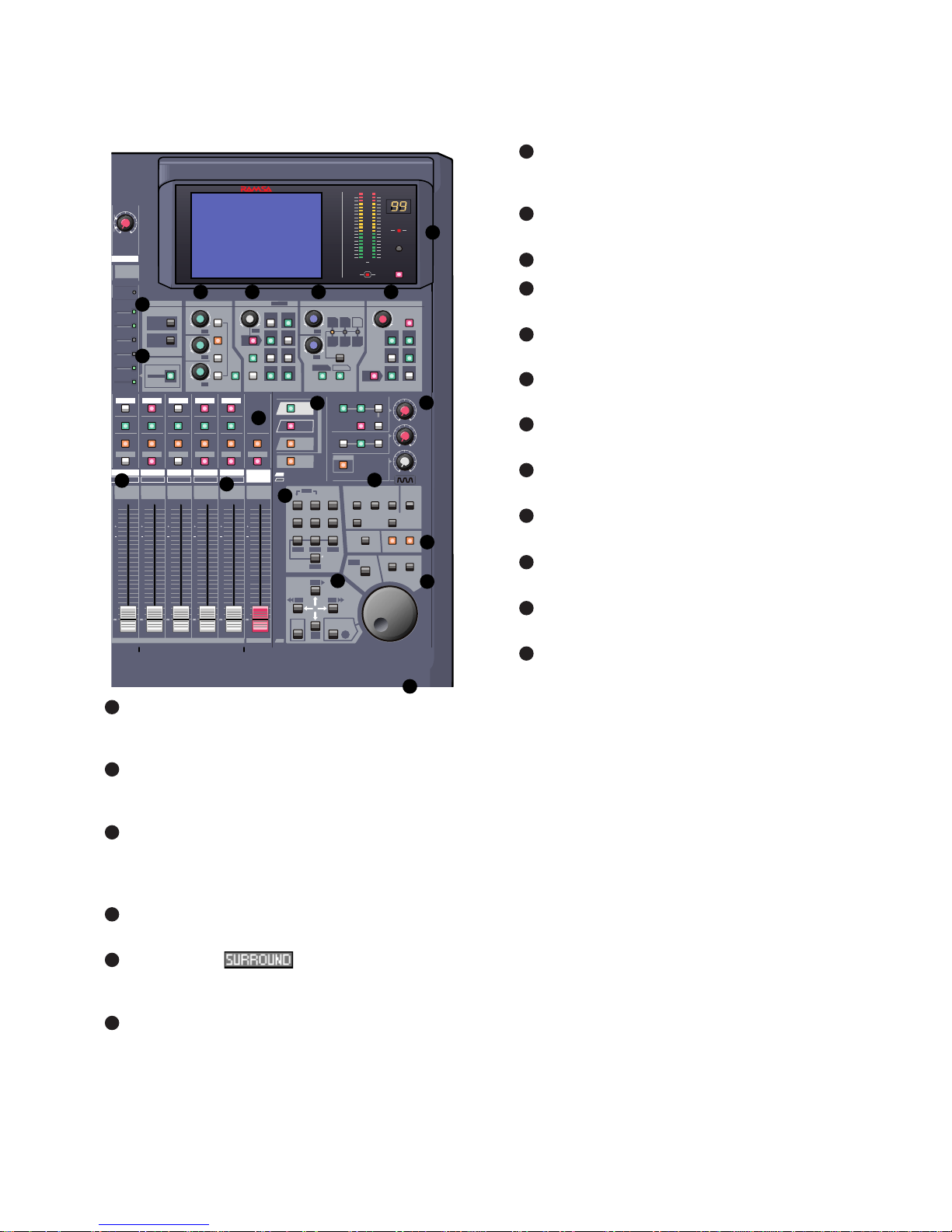
Major Operating Controls and Their Functions...................................................................................................... 1
Self Check Procedure.............................................................................................................................. 13
Wiring Diagram .......................................................................................................................................................... 21
Block Diagram
Overall Block Diagram.............................................................................................................................................. 22
Main Board (CPU Section) ....................................................................................................................................... 23
Main Board (Panel Control CPU Section)................................................................................................................. 24
Main Board (DSP Section-1) .................................................................................................................................... 25
Main Board (DSP Section-2) .................................................................................................................................... 26
Main Board (Audio Interface Section)....................................................................................................................... 27
AD/DA Board (1/2).................................................................................................................................................... 28
AD/DA Board (2/2).................................................................................................................................................... 29
Fader Drive Board (1/2)............................................................................................................................................ 30
Input Switch Board/Fader Drive Board (2/2)............................................................................................................. 31
HA Board and INS Board.......................................................................................................................................... 32
Monitor VR/HP/TB Boards........................................................................................................................................ 33
EFX Board ................................................................................................................................................................ 34
Block Diagram .......................................................................................................................................................... 35
Level Diagram........................................................................................................................................................... 36
Schematic Diagram
Monitor VR/HP/TB Boards........................................................................................................................................ 38
Bus Relay Board....................................................................................................................................................... 39
Power-1/Power-2 Boards.......................................................................................................................................... 41
HA Board and INS Board.......................................................................................................................................... 44
EFX/Meter Board...................................................................................................................................................... 45
Fader Drive Board .................................................................................................................................................... 47
Input Switch Board.................................................................................................................................................... 50
AD/DA Board (2/3).................................................................................................................................................... 52
AD/DA Board (3/3).................................................................................................................................................... 53
AD/DA Board (1/3).................................................................................................................................................... 54
Main Board (1/4)....................................................................................................................................................... 55
Main Board (2/4)....................................................................................................................................................... 56
Main Board (3/4)....................................................................................................................................................... 57
Main Board (4/4)....................................................................................................................................................... 58
WR-MTBR ................................................................................................................................................................ 59
WR-TNDM ................................................................................................................................................................ 62
WR-TDIF................................................................................................................................................................... 63
WR-SMPT................................................................................................................................................................. 66
WR-AESS................................................................................................................................................................. 67
WR-ADAT................................................................................................................................................................. 70
Conductor View
Monitor VR/HP/TB Boards........................................................................................................................................ 37
Bus Relay Board....................................................................................................................................................... 40
Power-1/Power-2 Boards.......................................................................................................................................... 42
HA Board and INS Board.......................................................................................................................................... 43
EFX/Meter Board...................................................................................................................................................... 46
Fader Drive Board .................................................................................................................................................... 48
Input Switch Board.................................................................................................................................................... 49
AD/DA Board ............................................................................................................................................................ 51
Main Board ............................................................................................................................................................... 57
WR-MTBR ................................................................................................................................................................ 60
WR-TNDM ................................................................................................................................................................ 61
WR-TDIF................................................................................................................................................................... 64
WR-SMPT................................................................................................................................................................. 65
WR-AESS................................................................................................................................................................. 68
WR-ADAT................................................................................................................................................................. 69
Exploded View
WR-DA7.................................................................................................................................................................... 71
WR-MTBR ................................................................................................................................................................ 72
WR-TNDM ................................................................................................................................................................ 73
WR-TDIF................................................................................................................................................................... 74
WR-SMPT................................................................................................................................................................. 75
WR-AESS................................................................................................................................................................. 76
WR-ADAT................................................................................................................................................................. 77
Replacement Parts List............................................................................................................................................. 78

– 1 –
MAJOR OPERATING CONTROLS AND THEIR FUNCTIONS
/CURSOR
16
BUS 2BUS 4BUS 6BUS 8
32
MONITOR A
MONITOR B
SOLO
MONITOR
2TR A
L/R
MONITOR A
L/R
2TR B
AUX
AUX
MONO
LEVEL
PRE
ON / OFF
FADER
CONTROL
12
56
34
BUS ASSIGN
PAN
12
7
4
3
6
8
DIRECT
L/R
ON
ON
5
PAN /ASSIGN / AUX
DYNAMICS / DELAY
EQUALIZERMASTER DISPLAY
H
HM
LM
ON
LEQ
Q
FREQ
GAIN
R
L+-
+-
+-
+-
+-
+-
ON
ON
PARAMETER SELECT
DYNAMICS
DELAY
BUS 1BUS 3 BUS 5BUS 7MASTER
L/R
16
BUS 4 BUS 6 BUS 7 BUS 8BUS 5 MASTER L/R
RATIO
ATK
RLS GAIN
DLY
THL
INPUT
1-16
INPUT
17-32
AUX
/ BUS
CUSTOM
/ MIDI
SURROUND
SUB
SL
LCR
SR
AUTO-
MATION
AUX
RED
GREEN
AUX 2
AUX 3
AUX 4
AUX 5
AUX 6
AUX 1
MMC
PLAY
REW FF
STOP
REC
12
45
78
0
3
6
9WRITE
UNDO/REDO READ
STORE RECALL
ABC DEF
JKLGHI MNO
TUV
PQRS WXYZ
UTILITY MIDI D-I/O
GROUP
AUTOMATION
SOLO SOLO SOLO SOLO SOLO
FLIP FLIP FLIP FLIP FLIP
ON ON ON ON ON ON
SELECT SELECT SELECT SELECT SELECT SELECT
0
10
10
40
30
20
0
10
10
40
30
20
0
10
10
40
30
20
0
10
10
40
30
20
0
10
10
40
30
20
0
10
10
40
30
20
INPUT
MIC/LINE
PEAK /
SIGNAL
+10 -60
010
010
010
T. B.
LEVEL
LIBRARY
SET UP
SHIFT
LOCATE
SET
REPLAY
LOOP
LOOP
SCENE MEMORY
PARAMETER
MONITOR
B LEVEL
MONITOR
A LEVEL
MIC
METER
CHANNEL
Digital Mixer WR - DA7
L R
50
35
25
OL
20
15
10
8
6
4
2
MEMORY
MULTI-
CH VIEW
CONTRAST
CONSOLE
LOCK
SOLO
CURSOR
MODE
TALK BACK
FADER
CH
EQ
PAN/SURR
LIBRARY
SEL/MAN
ENTER
ON
-10
+4
10
1
2
34 5 7
8
6
9
11 12
13
14
15
16
17
18
Illustrated Guide
Channel Strip – input gain controls with channel
control and status indicators. Also called a Channel
Fader Strip.
AUTOMATION/AUX LED button – selects the display
mode of the Channel Strip LED field indicators, and
arms the AUTOMATION system.
MASTER DISPLAY section – the METER and
CHANNEL buttons are direct buttons to the respective
LCD screen windows. These should be considered as
"home base" for the LCD display.
EQUALIZER section – controls for setting the
equalization parameters for a selected channel.
PAN/ASSIGN/ , BUS ASSIGN section –
controls for setting the pan and bus assignments for a
selected channel.
DYNAMICS/DELAY section – controls for setting the
onboard dynamics processing parameters for a
selected channel.
AUX section – controls for routing channels to outboard
sources and for defining the signal path as either pre-
fader or post-fader.
Display Bridge – contains the LCD screen, L/R meter
display, and primary mixer display status indicators.
BUS Fader Strip – controls for output BUSes.
MASTER L/R Fader Strip – controls for L/R MASTER
output.
Fader Layer Controls section – selects the current
fader layer to be displayed.
MONITOR section – volume and selection controls for
monitoring.
SETUP section – mixer function, or display control
buttons.
SCENE MEMORY section – buttons for writing and
reading the 50 mixer scene memories.
LIBRARY section – buttons for storing and recalling
Channel, EQ and Dynamics libraries.
Keypad – alphanumeric keys for entering numbers or
text.
Cursor Control section – buttons and controls for
defining the cursor actions.
Headset Control section – the location of the headset
connector and level control of the DA7 is immediately
below the right front edge of the Top Panel.
1
2
3
4
5
6
7
8
9
10
11
12
13
14
15
16
17
18

– 2 –
Fader
MIC/LINE INPUT knob
PEAK/SIGNAL LED
LED field indicators for AUX 1-6,
and automation parameters, CH,
EQ, PANASSIGN/SURR, LIBRARY
and SEL/MAN
SOLO LED button
FLIP LED button
SELECT LED button
On LED button
Channel Fader Strip
AUX/BUS Layer
function
Channel Fader Strip
1
Channel numbers
There are sixteen Channel Fader Strips on the
DA7
.
Depending on the selection of the four Fader Layer
controls, each strip directly controls (1) INPUT 1-16, (2)
INPUT 17-32, (3) AUX/BUS (indicated on the bottom of the
strip), and (4) a user CUSTOM/MIDI function.
The MIC/LINE INPUT knob varies the channel input gain
volume and adjusts for either a mic or line-level input. Due to
the high quality design of this circuit, there is no pad switch
necessary; the input knob range sets the input level. This
knob only affects the analog inputs 1-16.
The
PEAK/SIGNAL LED
indicates when an input signal is
present (
green
), and when the input signal level is too high
(
red
).
The LED field indicators reflect the auxiliary (AUX) routing
assignments and automation parameters. The LED color
signifies the AUTOMATION/AUX button selection; AUX
(
green
), AUTOMATION (
red
).
The SOLO LED button toggles on (
red
) or off. When on, the
channel output will be routed to the MONITOR A speakers
(overriding the MONITOR A input), and to the headphones.
The FLIP LED button flips the control of the Channel Fader
Strip from one input layer to the other. The LED color
indicates the current input selection and matches the Fader
Layer control LED button colors, INPUTS 1-16 (
green
) or
INPUTS 17-32 (
red
).
The SELECT LED button, when on (
orange
), identifies the
channel as the current channel selected. Only one Fader
Strip can be selected at a time (unless it’s in stereo or link
mode).
For more detail, see Chapter 5, Channel, Library, and
Meter Windows in the Users' Guide.
The ON LED button toggles on (
red
) and off. When on, the
channel output is active.
There are two channel numbers for each strip, indicating the
INPUT connections on the Rear Panel of the
DA7
.
The AUX/BUS label at the bottom of a Channel Fader Strip
indicates its function when the AUX/BUS Fader Layer
control is selected.
See Chapter 6, Fader Layers and Channel Strips in the
Users' Guide for additional information.
AUTOMATION/AUX LED Button
The AUTOMATION/AUX LED button toggles the display of
the Channel Fader Strips LED field indicators. The LED
color indicates the current selection.
See Chapter 14, Automation and Chapter 10, AUX in the
Users' Guide for additional information.
MASTER DISPLAY Section
Pressing the METER button will display the [METER]
window group on the LCD screen in the Display Bridge.
Pressing the METER button again will cycle the three
window selections: [METER INPUTS 1-32], [BUS/AUX],
[SLOT].
Pressing the CHANNEL button will display the [CHANNEL]
window group on the LCD screen in the Display Bridge.
The window displayed will show the current mixer strip
selected.
See Chapter 5, Channel, Library, and Meter Windows in
the Users' Guide for additional information.
AUTOMATION/AUX LED Button
2
METER button
CHANNEL button
MASTER DISPLAY Section
3

– 3 –
EQUALIZER Section
EQUALIZER Section
There are three parameter knobs and four frequency range
LED buttons in the EQUALIZER section, which are used to
change the EQ settings of the currently selected channel.
The EQ ON LED button toggles the EQUALIZER on (green)
and off. When the controls are active, adjustments can be
made to the currently selected channel.
The three knobs are labeled Q(quality), FREQ (frequency),
and GAIN (gain). The additional labeling of (left),
(surround left), and (surround subwoofer) indicate the
surround sound parameters that are controlled by the knobs
when the [SURROUND] mixing area is activated. Surround
sound capabilities are discussed in Chapter 8.
The four frequency band LED buttons can be selected one
at a time, and turn on (
orange
) to show which band is
operating. They are labeled H(high), HM (high-mid), LM
(low-mid), and L(low).
Pressing the GAIN knob displays the [EQUALIZER] window
on the LCD screen. Once the [EQUALIZER] is displayed in
the LCD window, these buttons perform other shortcut
functions.
The EQUALIZER section is detailed in Chapter 7 in the
Users' Guide.
PAN/ASSIGN/ , BUS ASSIGN
Section
PAN/ASSIGN/ , BUS ASSIGN Section
SUB SL
L
Pan, bus assignment, and surround sound parameters for
the selected channel is set within this area. The pan control
is always active for the L/R bus, so you do not need to
activate the ON button to pan across the Master L/R out.
However, if you wish to pan between odd/even buses, you
must push the ON button. Assignment to the DIRECT output
is not affected by the pan control.
The additional labeling of (center) indicates the
surround sound parameter that is controlled by the knob
when the [SURROUND] mixing area is activated.
The L/R, the DIRECT, and the BUS ASSIGN LED buttons
toggle on (
green
) and off. In addition to the eight bus
selections, labeled 1 - 8, selections for L/R (master L/R)
output and DIRECT output are available. The DIRECT
output works in conjunction with the option cards installed in
the
DA7
Rear Panel, routing signals directly to the cards.
The DIRECT output is detailed in Chapter 12, D-I/O (Digital
Input/Output) in the Users' Guide.
Pressing the PAN knob displays the [SURROUND] window
on the LCD screen.
The PAN/ASSIGN/ , BUS ASSIGN section of the
Top Panel is detailed in Chapter 8 in the Users' Guide.
DYNAMICS/DELAY Section
DYNAMICS and/or DELAY processing can be added to
each of the
DA7
Channels. Pressing the PARAMETER
SELECT button cycles the current parameter selections,
which are grouped in pairs. The top knob adjusts the top
parameter selection in the pair, and the bottom knob adjusts
the bottom parameter selection in the pair. The DYNAMICS
ON LED button toggles the dynamics processing on (
green
)
and off for the selected channel, and the DELAY ON LED
button toggles the delay on (
green
) and off.
The additional labeling of (right) and (surround
right) indicates the surround sound parameters that are
controlled by the knobs when the [SURROUND SOUND]
mixing area is activated. The surround sound function is
activated in the [SURROUND] window of the [SURROUND]
window group.
SR
R
C
EQUALIZER
H
HM
LM
ON
LEQ
Q
FREQ
GAIN +-
+-
+-
SUB
SL
L
Q (quality) parameter
knob or left surround
sound attenuator
FREQ (frequency)
parameter knob or
surround left surround
sound attenuator
GAIN parameter knob
or subwoofer surround
sound attenuator
Frequency band
LED buttons
EQ ON LED
button
4
PAN parameter
knob or center
surround sound
attenuator
PAN ON LED button
MASTER L/R LED
button
DIRECT LED button
BUS
ASSIGN
LED
buttons
5
THL (threshold),
ATK(attack), DLY
(delay) parameter knob
or right surround sound
attenuator
RATIO, RLS (release),
GAIN parameter knob
or surround right
surround sound
attenuator
DYNAMICS ON LED
button
PARAMETER
SELECT
LEDs
PARAMETER
SELECT
button
DELAY ON
LED button
6

– 4 –
See Chapter 8 in the Users' Guide for more information on
surround sound.
Pressing the bottom knob displays the [DYNAMICS] window
group on the LCD screen.
For more information on the DYNAMICS/DELAY section of
the Top Panel, see Chapter 9 in the Users' Guide.
AUX Section
AUX Section
This section of the Top Panel contains controls for routing
selected channels from/to outboard sources. These six aux
routes are independent of the channel input connecters on
the Rear Panel of the
DA7
and greatly expand the flexibility
of the mixer. They can be used as six mono sends, or in
stereo pairs (such as 1&2, 3&4, 5&6), and six mono returns
or stereo pairs. There are two digital aux routes, AUX 1/2,
and four analog aux routes, AUX 3/4 and AUX 5/6. These
are paired for convenience on the Rear Panel connectors. If
you wish to use them as Mono channels, connect a standard
audio “Y” cable (available at your dealer) to split the audio
channels.
Display Bridge
With a channel selected, press an AUX 1-6 LED button
(green) to select which aux route you wish to assign for the
channel. The LEVEL knob performs two functions. By
pressing the knob, you will assign the channel to the
selected aux route, and by turning the knob, you can adjust
the individual channel output to the aux selection. The LED
field of the Channel Fader Strips will reflect the aux
assignments for the channels.
Aux routing is defaulted to a post-fader condition for the
selected channel. Press the PRE LED button to select it
(
red
) and change the aux routing function to a pre-fader
condition.
Press the FADER CONTROL LED button to select it (red)
and display the [FADER CONTROL] window group on the
LCD screen. The window displayed will be determined by
the current AUX 1-6 LED button selection. The channel
fader status of the 32 input channels for the aux selected will
be reflected in the [FADER CONTROL] window, and the
Channel Faders will reset to their respective level positions
for the aux selected.
The AUX/BUS designations at the bottom of the Channel
Fader Strips identify the strip functions when the Fader
Layer AUX/BUS LED button is pressed.
For more information on the AUX section of the Top Panel
see Chapter 10 in the Users' Guide.
7
Send LEVEL
volume and assign
ON/OFF knob
FADER CONTROL
mode LED button
PRE LED button
AUX 1-6 select
LED buttons
LCD screen
L/R Meter display
MEMORY numeric readout
CONSOLE LOCK LED status indicator
LCD CONTRAST control knob
MULTI-CH VIEW LED button
SOLO LED status indicator
Display Bridge Section
The Display Bridge contains the information for the current status of the
DA7
and the LCD screen. The various windows for the
functions and features of the mixer are displayed on the LCD screen.
8

– 5 –
BUS Fader Strip
BUS Fader Strip
There are four BUS Fader Strips on the
DA7
. In
conjunction with the Fader Layer controls, each strip directly
controls the BUS outputs, or the AUX/BUS functions which
are indicated on the bottom of the strip or a user
CUSTOM/MIDI function.
The SOLO LED button toggles on
(red)
or off. When on, the
selected bus output will be routed to the MONITOR A
speakers and headphones, overriding the previous input.
There are two bus numbers for each strip, indicating the
BUS ASSIGN selections that can be controlled by the strip.
The FLIP LED button flips the BUS Fader Strip from
controlling one bus to controlling the other bus for the strip.
The LED color
(red
or
green)
indicates the current bus
selection.
The SELECT LED button, when on
(orange)
, identifies the
bus strip as the current bus strip selected. Only one BUS
Fader Strip can be selected at a time unless they are paired
for LINK or STEREO operation.
The ON LED button toggles on
(red)
and off. When on, the
bus output is active.
The AUX/BUS indication at the bottom of the BUS Fader
Strip indicates the strip function when the AUX/BUS Fader
Layer control is selected.
See Chapter 6, Fader Layers and Channel Strips in the
Users' Guide for additional information.
MASTER L/R Fader Strip
The MASTER L/R Fader Strip controls the
DA7
master L/R
output.
The SELECT LED button, when on
(orange)
, identifies the
strip as the current fader strip selection.
The ON LED button toggles on
(red)
and off. When on, the
master output is active.
See Chapter 6, Fader Layers and Channel Strips in the
Users' Guide for additional information.
Fader Layer Controls Section
The Fader Layer controls significantly expand the flexibility
of the
DA7
mixer. The LED button selections define the
current function for the fader strips.
LED buttons for the Fader Layer controls assist you in
determining or checking the current channel and bus fader
settings on the mixer.
INPUT 1-16, when selected
(green)
, resets the fader strips
to control channel inputs 1 through 16, and buses 1, 3, 5,
and 7. When selected, the faders move to the positions
reflecting the current settings for the layer, unless previously
flipped. To reset a flipped Channel Fader Strip, press the
FLIP button. To reset all the currently flipped Channel
Fader Strips, press the INPUT 1-16 Fader Layer control
button and hold it or two seconds. This will set all faders to
the selected layer.
Fader
AUX/BUS Layer function
SOLO LED button
FLIP LED button
SELECT LED button
ON LED button
Bus Assign
numbers
9
Fader
AUX/BUS Layer function
SELECT LED button
ON LED button
10
11
INPUT 1-16 LED
button
(green)
INPUT 17-32 LED
button
(red)
AUX/BUS LED button
(orange)
CUSTOM/MIDI LED
button
(orange)

– 6 –
INPUT 17-32, when selected
(red)
, resets the fader strips to
control channel inputs 17 through 32, and buses 2, 4, 6, and
8. When selected, the faders move to the positions reflecting
the current settings for the layer, unless previously flipped.
To reset a flipped Channel Fader Strip, press the FLIP
button. To reset all the currently flipped Channel Fader
Strips, press the INPUT 17-32 Fader Layer control button
and hold it for two seconds. This will set all faders to the
selected layer.
AUX/BUS, when selected
(orange)
, resets the fader strips to
control the aux sends, aux returns, and bus outputs, while
the faders move to the positions reflecting the current fader
settings for the layer.
CUSTOM/MIDI is a user-definable Fader Layer control,
where the functions are selectable.
See Chapter 11, MIDI for more information on the
DA7
MIDI
feature, and Chapter 6, Fader Layers and Channel Strips
in the Users' Guide for additional information.
MONITOR Section
MONITOR Section
The
DA7
provides controls for two monitor outputs and a
talkback circuit. There are source selection LED buttons for
the MONITOR A and MONITOR B outputs, and LEVEL
knobs for both of the monitor outputs and the talkback
circuit.
MONITOR A Controls
The MONITOR A selection LED buttons route the input
selected
(green)
to the MONITOR A OUTPUT (CR) (Control
Room) connections on the Rear Panel of the mixer and to
the headphones. The selections are:
8L/R routes the MASTER L/R output to the monitors.
82TR A routes the device that is connected to 2TR A IN
on the Rear Panel to the monitors.
82TR B routes the device that is connected to 2TR B IN
on the Rear Panel to the monitors.
8AUX routes the AUX SEND outputs to the monitors.
Press the AUX LED button to monitor the selections,
beginning with AUX SEND 1/2, followed by AUX SEND
3/4, and AUX SEND 5/6. The MEMORY numeric
readout on the Display Bridge will momentarily display
the AUX SEND selections.
The MONO button, when on
(red)
, sums the selected input
and sends a monaural signal to the monitors. This will not
affect the 2TR B output stereo signal.
MONITOR B Controls
The MONITOR B selection LED buttons route the input
selected
(green)
to the MONITOR B OUTPUT (STUDIO)
connections on the Rear Panel of the mixer. The selections
are:
8MONITOR A routes the current MONITOR A selection
to the studio monitors.
8AUX routes the AUX SEND outputs to the monitors.
Press the AUX LED button to monitor the selections
beginning with AUX SEND 1/2, followed by AUX SEND
3/4, and AUX SEND 5/6. The MEMORY numeric
readout on the Display Bridge will momentarily display
the AUX SEND selections.
TALKBACK
The TALKBACK ON button controls the talkback
microphone installed in the Top Panel of the
DA7
. When on
(orange)
, the MIC is active and the MONITOR A speakers
will be dimmed. This can be either a “push-to-talk”
momentary interrupt type button, or a “push on/push off”
type button. This is selected in the [UTILITY] window.
Talkback routing is selected in the [SOLO MONITOR]
window. There is also a phone jack on the Rear Panel that
allows for remote Talk back operation.
For additional information on the talkback, see Chapter 16,
Utility and Solo monitor in the Users' Guide.
SETUP Section
SETUP Section
These are direct-action buttons that will display the selected
windows in the LCD screen of the Display Bridge.
12
MONITOR A
MONITOR B
2TR A
L/R
MONITOR A
L/R
2TR B
AUX
AUX
MONO
010
010
010
T. B.
LEVEL
MONITOR
B LEVEL
MONITOR
A LEVEL
MIC
TALK BACK
ON
MONITOR A
source selection
buttons
MONITOR B
source selection
buttons
Talkback ON LED
button
LEVEL
knobs
SOLO
MONITOR
UTILITY MIDI D-I/O
GROUP
AUTOMATION
SET UP
MIDI button
UTILITY
button
GROUP
button
D-I/O button
SOLO MONITOR
button
AUTOMATION
button
13

– 7 –
UTILITY Button
Pressing the UTILITY button will display the [UTILITY]
window group on the LCD screen in the Display Bridge.
The window displayed will be determined by the window
selection buttons at the bottom of the window. Pressing the
UTILITY button again will cycle the window selections:
[OSC_BATT], [CONFIGuration], [USER CuSToM].
See Chapter 16, Utility and Solo Monitor in the Users'
Guide for additional information.
MIDI Button
Pressing the MIDI button will display the [MIDI] window
group on the LCD screen in the Display Bridge. Pressing
the MIDI button again will cycle the window selections:
[SETUP], [PRoGram ASsiGN], [ConTRoL ASsiGN],
[BULK], [REMOTE].
See Chapter 11, MIDI for additional information.
D-I/O Button
Pressing the D-I/O button will display the [D-I/O] (Digital
Input/Output) window group on the LCD screen in the
Display Bridge. Pressing the D-I/O button again will cycle
the window selections: [INPUT SET], [TO SLOT],
[DITHER].
See Chapter 12, D-I/O for additional information.
GROUP Button
Pressing the GROUP button will display the [GROUP]
window selections on the LCD screen in the Display
Bridge. Pressing the GROUP button again will cycle the
window selections: [FADER GRouP], [MUTE GRouP],
[LINK/STR].
See Chapter 13, Group for additional information.
AUTOMATION Button
Pressing the AUTOMATION button will display the
[AUTOMATION] window group on the LCD screen in the
Display Bridge. Pressing the AUTOMATION button again
will cycle the window selections: [SETUP], [EXECUTE],
[EVenT EDIT] .
See Chapter 14, Automation for more information.
SOLO MONITOR Button
This button displays Solo Monitor mode, Talk back
assignment and Surround Monitor.
See Chapter 16, Utility and Solo Monitor in the Users'
Guide for additional information.
SCENE MEMORY Section
SCENE MEMORY allows you to store and recall complete
mixer setups and functions. There are fifty registers,
numbered 01 through 50, available for storage of mixer
settings. Memory 00 is reserved for Automation.
Press either the WRITE LED button or the READ LED
button
(orange)
to select it and display the [ReaD/WriTe]
window of the [SCENE MEMORY] window group on the
LCD screen of the Display Bridge.
There are two windows in the group: [RD/WT], [XFADE].
The [RD/WT] window is always the initial window displayed
when either button is selected. To change to the [XFADE]
window, use the ARROW buttons to navigate to the
respective window selection button and then press the
ENTER button, or press either the WRITE or READ LED
buttons a second time.
When the [RD/WT] window is displayed, the JogDial is
enabled to scroll the [SCENE MEMORY] list area of the
window. This allows you to quickly access a previously
stored scene, locate an empty scene memory, or locate a
scene memory to be overwritten. By pressing the ENTER
button after a scene has been located, the mixer will
immediately assume the setting for the stored scene.
The MEMORY readout display will flash the memory number
that is selected until it is recalled. The selected memory will
be displayed without flashing once it has been recalled.
While the [RD/WT] window is displayed, pressing the
ENTER button will immediately overwrite the current scene
memory with the settings on the mixer at the moment the
ENTER button is pressed, unless the register is write-
protected. See Chapter 15, Scene Memory in the Users'
Guide for additional information.
LIBRARY Section
LIBRARY Section
There are three mixer functions with associated libraries:
CHANNEL, EQUALIZER, DYNAMICS/DELAY. The library
feature allows you to store and recall individual function
parameters to a separate library. There are fifty registers for
each library, numbered 01 through 50.
WRITE LED button READ LED button
14
15
STORE LED button RECALL LED button

– 8 –
The RECALL button opens the library window for the
selected function. What this means is that if the [CHANNEL]
window was displayed when you pressed the RECALL
button, the CHANNEL library will be displayed. The same
goes for the EQUALIZER AND DYNAMICS/DELAY
libraries. Once selected, the parameter knob will allow you
to scroll through the stored memories. After you have
chosen a memory, press the RECALL button again and the
selected memory will be recalled to the currently selected
function. You will also automatically return to the main
screen for the selected function.
While the library is displayed, pressing the STORE button
will immediately store the current function settings to the
current memory location, unless the memory location is
write-protected.
See Chapter 5, Library in the Users' Guide for additional
information.
Keypad and Cursor Control Section
Keypad
Display Bridge
Cursor Control Section
Details on the Keypad, UNDO/REDO button,
MMC/CURSOR button, ARROW buttons, ENTER button,
CURSOR MODE button, and JogDial elements of the
DA7
Top Panel are provided in Chapter 4 in the Users' Guide.
Headset Control Section
A stereo headset connector and headset volume control are
located under the right front edge of the Top Panel of the
DA7
. The current MONITOR A selection is always routed to
the headset connector.
16
17
12
45
78
0
3
6
9
ABC DEF
JKLGHI MNO
TUV
PQRS WXYZ
SHIFT
LOCATE
SET
REPLAY
LOOP
LOOP
ARROW buttons
ENTER button
CURSOR
MODE button
JogDial
UNDO/REDO button
MMC/CURSOR button
18
Display Bridge Section
The Display Bridge for the
DA7
is your “window” to the mixer functions and features. The elements comprising the Display Bridge
are the LCD screen, the L/R meter display, the MEMORY numeric readout, the CONSOLE LOCK LED status indicator, the
CONTRAST control knob, the MULTI-CH VIEW (multi-channel) LED button, and the SOLO LED status indicator.
LCD screen
L/R meter display
MEMORY numeric readout
CONSOLE LOCK LED status
indicator
LCD CONTRAST control knob
MULTI-CH VIEW LED button
SOLO LED status indicator

– 9 –
LCD Screen
Taskbar
Sample Window Display (CHANNEL window displayed)
Function area
Window selection buttons
The LCD screen is the 320x240 backlit liquid-crystal display (LCD) element of the Display Bridge. The screen displays the various
windows that show the functions and status of the
DA7
. The windows contain areas and items that can be accessed with the cursor
control or JogDial.
There are three general areas for the windows displayed on the LCD screen: the [taskbar] area, the [function] area, the [windows
selection buttons] area.
Taskbar Area
Channel type field Current window SCENE MEMORY field
name
Channel selection field Window group name Communication Timecode field
status indicator
Taskbar Area
The [taskbar] area of a window contains information about
the current window and the most recent mixer selections.
Several of the items in the [taskbar] will remain unaffected
when you change to another window, depending on the new
window selection.
Channel Selection Field
This field shows the currently selected Channel, BUS, or
MASTER L/R strip selection. When channels or buses are
paired, the field will display both numbers. The field will
change when you press a different SELECT LED button on
the Top Panel.
Channel Type Field
This field shows the most recently selected channel type.
The field will change when you press a SELECT LED button
on the Top Panel.
Window Group Name
The current window group name is displayed in this field.
Current Window Name
The name of the current window is displayed in this field.
Communication Status Indicator
This area of the [taskbar] displays the current
communication status as configured in the [MIDI>SETUP]
window. The selections are either [TO PC], [S I/O], or
[MIDI].
Timecode Field
This field displays the most recent time code value received
by the mixer, as defined by the settings in the
[AUTOMATION>EXECUTE] window.
SCENE Field
This field displays the most recently read SCENE MEMORY
number and name.

– 10 –
Function Area
The [function] area of a window contains the various
controls, buttons, settings, and values for the current
window.
Window Selection Buttons Area
This area of a window contains the buttons for the windows
that comprise the current window group. The button for the
current window will be highlighted.
L/R Meter Display
This meter reflects the current MASTER L/R (left/right)
output of the
DA7
, unless SOLO has been activated for a
channel. If a SOLO LED button is selected on the mixer, the
meter reflects the level of the solo’d channel(s) only.
In the [METER>SLOT] window, the [RESPONSE] area lets
you select between [VU] (Volume Units) and [PPM] (Pulse
Position Modulation). When [VU] is selected, the L/R Meter
Display will show the mixer output in Volume Units, and
when [PPM] is selected, the Meter reflects the mixer output
as Pulse Position Modulation.
SOLO LED Status Indicator
Located below the L/R meter display, the SOLO LED status
indicator will light and flash
(red)
when SOLO has been
activated for any channel on the mixer.
MEMORY Numeric Readout
The two-digit numeric readout displays the most recently
accessed SCENE MEMORY. Whenever an AUX monitoring
selection button is activated for either MONITOR A or
MONITOR B, the numeric display will momentarily display
the AUX selections.
CONSOLE LOCK LED Status Indicator
When illuminated
(red)
, the password protection for an area
or function of the mixer is engaged, and selected mixer
operations cannot be performed.
See Section 16-3, [UTILITY>CONFIG] Window for more
information.
CONTRAST Control Knob
This knob controls the contrast value of the LCD screen.
Rotate the knob to adjust the contrast value of the LCD
screen for optimum viewing and to suit the operating
environment.
MULTI-CH VIEW LED Button
Press this LED button to activate the multi-channel viewing
mode for the LCD screen. When on (red), the LCD screen
will display the currently selected Channel Fader and one of
other sources that can be used to compare or copy
information from the current selection.
See Chapter 5, Channel, Library, and Meter Windows in
the Users' Guide for more information.
L/R Meter Display
SOLO LED status indicator
SOLO
SOLO LED Status Indicator
MEMORY
MEMORY Numeric Readout
CONSOLE
LOCK
CONTRAST
MULTI-
CH VIEW

– 11 –
Rear Panel
Everything that goes in, out, and through the
DA7
happens
on the Rear Panel, with the exception of the headphone
connector. The
DA7
provides multiple ways for doing many
things, so let your creativity be your guide.
The rear of the
DA7
is configured in four rows. The top row
contains analog INPUTS 1-16 (inputs 1-8 are balanced XLR
connectors and inputs 9-16 are balanced TRS (tip-ring-
sleeve) phone plug connectors).
Row 2 contains analog INS 1-16 (inserts) with (TRS) phone
plug connectors. Row 3 contains outputs for MASTER OUT,
REC OUT analog, MONITORS A&B, and AUX returns and
sends 1 through 6. The bottom row contains the METER
BRIDGE connection, MIDI IN/OUT, SERIAL PORT (for
direct connection to a PC or a Macintosh computer), WORD
CLOCK IN/OUT, DIGITAL IN/OUT, and a REMOTE SW
connector.
THIS EQUIPMENT COMPLIES WITH THE REQUIREMENTS FOR
A CLASS A COMPUTING DEVICE IN FCC RULES PART 15
SUBPART J. OPERATION OF THIS DEVICE IN A RESIDENTIAL
AREA MAY CAUSE HARMFULL INTERFERENCE REQUIRING THE
USER TO TAKE WHATEVER STEPS MAY BE NECESSARY TO
CORRECT THE INTERFERNCE.
WARNIG
- TO REDUCE THE RISK
OF FIRE OR ELECTRIC
SHOCK. DO NOT EXPOSE
THIS APPLIANCE TO
RAIN OR MOISTURE.
CAUTION
- TO REDUCE
THE RISK OF ELECTRIC SHOCK,
DO NOT REMOVE COVER. NO USER SERVICEABLE PARTS
INSIDE. REFER SERVICING TO QUALIFIED SERVICE
PERSONNEL.
CAUTION
- MAKE SURE THE POWER OF THE UNIT IS TURNED OFF
WHEN INSERTING OPTION CARDS INTO THE SLOTS OF THE UNIT.
OTHERWISE THE UNIT MAY BE DAMAGED.
RING
SLEEVE
METER BRIDGE I/F MIDI SERIAL PORT WORD CLOCK
AC IN
POWER
SIGNAL
GND
TIP
CONNECTION
INPUT/OUTPUT
NO 1:GND
NO 2:HOT
NO 3:COLD
INS
TIP:SEND
RING:RETURN
SLEEVE:GND
AUX
TIP:ODD
RING:EVEN
SLEEVE:GND
OdB is referenced to 0.775Vrms
CH17–24/SLOT 1
CH25–32/SLOT 2
TANDEM/
CH9-16
/BUS & AUX INSERT/SLOT3
ON
OFF
OUT
TO PC OUT
/THRU
REC OUT 2TR A IN / INPUT15.16
IN
IN RS422 / 485 110
OFF ON
75
OFF ON
DIGITAL IN / OUT
AUX2TR B IN (ANALOG)
MONITOR A OUT
(CR)
MONITOR B OUT
(STUDIO)
REC OUT
(ANALOG)
MASTER OUT
RETURN
5/6RL
RLRLRL
RL
3/4 5/6 3/4 1/2 1/2
RETURN SEND
SEND
+4dB 10k (UNBAL) (S/PDIF)
+4dB 10k (BAL)
–60dB to +10dB 5k (BAL/UNBAL)
+4dB 10k (UNBAL)
+4dB 10k (BAL)
+4dB 600 (BAL/UNBAL)
SMPTE & V SYNC
+4dB 600
(BAL)
+4dB 600
(BAL)
REMOTE SW
AES/EBU
S/PDIF
Talk on/off
Rec on/off
INS16 INS15 INS14 INS13 INS12 INS11 INS10 INS9
INPUT16 INPUT15 INPUT14 INPUT13 INPUT12 INPUT11 INPUT10 INPUT9 INPUT8 INPUT7 INPUT6 INPUT5 INPUT4 INPUT3 INPUT2 INPUT1
INS8 INS7 INS6 INS5 INS4 INS3 INS2 INS1
DA7 Rear Panel
Signal Gnd (signal ground)
AC Inlet
Power switch
Power Switch
Turns the power on and off to the
DA7
.
AC Inlet
Plug the AC power cord here.
Signal Ground [SIGNAL GND]
Connect to a grounded source to stabilize the voltage levels of the connected devices, and to prevent hum and buzz created by
ungrounded sources.
Rows 1 & 2 Connectors
Inputs 9-16 (TRS). Use these for
balanced -60 to +10 signals Inputs 1-8 (XLR). Use these for balanced
-60 to +10 signals. Phantom powered
Channel 1-16 Inserts. These are TRS send and return connectors.
Cutaway of DA7 Rear Panel (Rows 1 and 2) Input and Insert Connectors
INPUTS 1-8
These inputs are designed for XLR connectors. The input
range is from -60dB to +10dB, 5k ΩBAL. Use the MIC/LINE
INPUT knobs on the Channel Strips for adjustment of the
incoming level. From the [CHANNEL] window, the +48V
phantom power can be individually turned on or off for each
channel via the screen.
INPUTS 9-16
Use these inputs with a 1/4” TRS (tip-ring-sleeve) phone
plug connector. Use the MIC/LINE INPUT knob to adjust the
input level. The input range is from -60dB to +10dB, 5k Ω
BAL. There is no +48V phantom power. Microphones used
on these inputs must be externally powered if required.

– 12 –
INSERTS 1-16
These inserts are used for creating an effects loop. A 1/4”
TRS phone plug, with a level of +4 dB, 10k ΩUNBAL,
provides an output (tip) send to effects, or an input (ring) return
from an outboard effects device.
Monitor B Out
These terminals are 1/4” TRS dual phono plugs at a level of
+4dB, 600ΩBAL, and connect the output of the MONITOR
Bsource selection to an external amplifier for monitoring in
the studio.
Row 4 Connectors
[REC OUT] Record Output
Use 1/4” TRS phone plugs, at a level of +4dB, 10kΩBAL, to
output signals for recording.
Master Output
Female XLR connectors send the MASTER L/R analog
program output to external speakers and/or a recording
device of +4 dB, 600ΩBAL.
Meter Bridge
connector
(Option).
MIDI In and Out connectors
Serial I/O
connectors
Wordclock In and Out /
Thru connectors
2TR Input Digital (XLR)
Format select switch
Remote switch connector for Talkback
ON/OFF and automation REC ON/OFF
Cutaway of DA7 Rear Panel Row (4) Digital and Serial Connectors
Record Out Digital(XLR)
RS terminating
switch
Clock terminating &
OUT / Thru switch
Remote SW [Switch]
Connect a momentary or press-to-talk switch with a 1/4” TS
phone plug for Talk Back or automation record functions.
Parameters are assignable in the [UTILITY>CONFIG]
window.
Digital Input [AES/EBU]
An XLR connector inputs an audio signal from a DAT or
other digital source. Assignments can be made from the [D-
I/O>INPUT SET] window.
Row 3 Connectors
This incoming source can be monitored by selecting the 2TR
ALED button as the MONITOR A source selection, or, on
Channel Faders 15 and 16, when 2TR A is assigned in the
[D-I/O>INPUT SET] window. The signal can also be directly
assigned to the MASTER L/R program output.
Digital Record Output [AES/EBU]
XLR connections of the MASTER L/R digital output are for
use in recording by a digital device with AES/EBU digital
input capabilities.
Master L/R outputs
(Analog XLR balanced)
Record L/R outputs
(Analog TRS balanced)
Monitor B outputs
(Analog TRS balanced)
Monitor A outputs
(Analog TRS balanced)
2TR B input connectors
(Analog TRS balanced)
Aux Returns 3/4 and
5/6 (Analog TRS)
Aux Sends 3/4 and 5/6
(Analog TRS)
Aux 1/2 send and return
(Digital RCA, S/PDIF)
Cutaway of DA7 Rear Panel (Row 3) Output Connectors

– 13 –
AUX SEND 1/2
Use RCA connectors to attach a digital effects device or
another S/PDIF device to the AUX SEND 1/2 and AUX
RETURN 1/2 digital terminals. AUX/BUS Fader Layer
faders control the AUX 1/2 SEND and RETURN. These
connections are not analog signals.
AUX SEND 3/4, 5/6
These terminals are 1/4” TRS phone plug connectors, at a
level of +4dB, 10kΩUNBAL. They can be used for
connecting outboard signal processing devices, or for a
studio headphone feed, or as part of a multitrack output
setup. The possibilities are limited only by your imagination.
The AUX/BUS Fader Layer is the fader control for these
connections.
AUX RETURN 3/4, 5/6
These terminals are 1/4” TRS phone plug connectors, at a
level of +4dB, 10kΩUNBAL. The AUX/BUS Fader Layer is
the fader control for these feeds.
2-Track B Input
This is used to connect an analog source strictly for
monitoring purposes, as it does not appear as an input to
the mixer. Connect a 1/4” TRS phone plug to the output
signal from a cassette deck, for example. The input signals
are sent to the 2 TR B IN LED button in the monitor section.
The level is +4dB, 10kΩBAL.
Monitor A Out
These terminals are 1/4” TRS dual phone plugs at a level of
+4dB, 600ΩBAL, and connect the output of the MONITOR
Ato an external amplifier (or powered speaker) for
monitoring in the control room (CR).
Format Select Switch
This switch is used to select the signal format of the
connected device, either AES/EBU or S/PDIF. The digital
input and output are both switched. For S/PDIF usage, an
optional adapter is required. You must make certain that the
adapter connects pin #1 and #3 together.
Clock Terminating 75 ΩON/OFF & Out / Thru
Switch
Next to the WORD CLOCK IN BNC connection, this switch
should be set to 75 ΩOFF and Thru position if the
DA7
is
being used to pass the wordclock signal to other devices in
the chain.
Set the switch to 75 ΩON and OUT for terminating the
wordclock, if the
DA7
is slaved and located at the end of the
wordclock chain. The 75 ΩON and OUT position should
also be selected when the
DA7
is being used to slave other
devices to the
DA7’s
wordclock. See Chapter 12, D-I/O in
the Users' Guide for more information.
Clock Input
This is used to synchronize the
DA7
to an external word
clock source. This allows the
DA7
’s internal clock to slave to
another reference, such as a digital multi-track deck or other
device. Use a BNC connection to attach an external
wordclock source.
Clock Output
This is used to slave an external device, such as a digital
multi-track machine, to the
DA7
internal clock. It can also be
used to relay an external wordclock that is being used to
synchronize the
DA7
to an external device. Using a BNC
connector, other devices can synchronize to the
DA7
wordclock.
Serial Terminating Switch
Set the switch to ON if the
DA7
is the termination point of
the RS-422/485 serial transmission path. The 110Ωswitch
turns this function OFF/ON.
Serial Port [RS-422/485]
Use this serial port to connect an IBM compatible computer
having an RS-422/485 port. Connect to the
DA7
with a D-
SUB 9-pin connector. Optional remote control software for
your computer can be used to control the
DA7
, thus
expanding the features and capabilities of the mixer.
Serial Port [TO PC]
Use this serial port to connect with a Macintosh computer. If
the computer is an IBM compatible, you may need a
conversion cable that changes a Mini-DIN 8 pin (for TO PC)
to a D-sub 9 pin(for RS-232C), available at nearest dealer.
Optional remote control software for your computer can be
used to control the
DA7
, thus expanding the features and
capabilities of the mixer.
MIDI IN
This connector is used to receive signals from peripheral
MIDI devices.
MIDI OUT
This connector is used to send signals to peripheral MIDI
devices. The
DA7
can be used as a MIDI controller. See
Chapter 11, MIDI in the Users' Guide for details.
METER BRIDGE Connector
This is used to connect the optional Meter Bridge for the
DA7
.
See Chapter 17, Options in the Users' Guide for more
details.

– 14 –
Option Card Slots
There are three slots for the optional audio Input/Output
cards, plus one dedicated slot for the SMPTE/V SYNC card.
The space for the SMPTE/V SYNC card is located directly
under the MASTER OUT XLR connectors. Audio option
cards are next to the power switch. The audio option cards
can be used in any of the audio slots, but for TANDEM
operation, the TANDEM card MUST be used in Slot 3.
Video Sync Input [V SYNC]
This is used to connect a vertical synchronizing signal from
a video device.
See Chapter 17, Options in the Users' Guide for more
about SMPTE/V SYNC.
Digital I/O Slot 1 [CH17-24/SLOT 1]
When an option card is inserted into Slot 1, the output of the
connected device appears on Channel Faders 17 through
24, and is controlled by the Fader Layer Inputs 17-32.
Digital I/O Slot 2 [CH25-32/SLOT 2]
When an option card is inserted into Slot 2, the output of the
connected device appears on Channel Faders 25 through
32, and is controlled by the Fader Layer Inputs 17-32.
Digital I/O Slot 3 [CH9-16/SLOT 3]
When an option card is inserted into Slot 3, the output of the
connected device appears on Channel Faders 9 through
16, and is controlled by the Fader Layer Inputs 1-16. This
connection REPLACES the analog inputs 1-16 with
whatever is connected to the option card in Slot 3.
For more information regarding optional slots, see Chapter
12, D-I/O and Chapter 17, Options in the Users' Guide.
Slot 1
Slot 2
Slot 3 SMPTE/V SYNC
card slot
Option Card Slots
SELF CHECK FUNCTION
8The Self Check Function is incorporated in the Digital
Audio Mixer WR-DA7.
1. Test Equipment Required
8The following Test Jigs are required for Self Check and
Service of the WR-DA7.
8AD EXTD-1 (Part Number : YWA0EA1196AN) between
the Power-2 Board and AD/DA Board as shown in fig. 1-1.
Fig. 1-1
8SLOT EXTD (Part Number : YWA0EA1198AN) for the
optional Board as shown in fig. 1-2.
Fig. 1-2
8AD EXTD-2 (Part Number : YWA0EA1199AN) between
the Main Board and AD/DA Board as shown in fig. 1-3.
Fig. 1-3
8PC RTN (Part Number : YWA0EA1200AN) for the PC
Connector as shown in fig. 1-4.
Fig. 1-4
Table of contents
Other Ramsa Music Mixer manuals
Popular Music Mixer manuals by other brands

Crest Audio
Crest Audio CENTURY LMX manual

Pioneer
Pioneer DJM-2000 Firmware update manual

STK Professional Audio
STK Professional Audio SM-16S DDR PowerPlus owner's manual

HZ Sound Systems
HZ Sound Systems Qmix owner's manual

Zoom
Zoom LiveTrak L-20 Operation manual

Euphonix
Euphonix System 5 installation guide