LAWO ruby User manual


Copyright
All rights reserved. Permission to reprint or electronically reproduce any document or graphic in whole
or in part for any reason is expressly prohibited, unless prior written consent is obtained fromthe Lawo
AG.
All trademarks and registered trademarks belong to their respective owners. It cannot be guaranteed that
all product names, products, trademarks, requisitions, regulations, guidelines, specifications and norms
are free from trade mark rights of third parties.
All entries in this document have been thoroughly checked; however no guarantee for correctness can
be given. Lawo AG cannot be held responsible for any misleading or incorrect information provided
throughout this manual.
Lawo AGreserves the right to change specifications at any time without notice.
© Lawo AG, 2021

3/78
Table of Contents
ruby User Manual Version: 6.6.0/1
Table of Contents
1. Introduction ......................................................................................................................................... 4
2. Important Safety Instructions ................................................................................................................ 5
3. The Hardware ..................................................................................................................................... 6
4. Installation ......................................................................................................................................... 14
5. SystemSetup .................................................................................................................................... 22
6. Operation .......................................................................................................................................... 28
7. Maintenance ..................................................................................................................................... 60
8. Troubleshooting ................................................................................................................................. 67
9. Appendices ....................................................................................................................................... 70

ruby User ManualVersion: 6.6.0/14/78
1. Introduction
1. Introduction
Welcome to ruby.
About this Manual
This document describes all aspects of the ruby control surface, including its hardware components, installation,
connections, operation and maintenance.
The surface requires a DSP Core such as Power Core and, optionally, may run with a VisTool MK2 touch-
screen interface. You can find more information on these products in the relevant manuals.
Look out for the following which indicate:
Notes - points of clarification.
Tips - useful tips and short cuts.
Attention - alert you when an action should always be observed.
Further Information
Mechanical drawings and data sheets (including weights and dimensions) are available from the Download-
Center (after login).
Lawo User Registration
For access to the Downloads area and to receive regular product updates, please register at:
www.lawo.com/registration.

ruby User Manual Version: 6.6.0/1 5/78
2. Important Safety Instructions
2. Important Safety Instructions
Please observe all of the instructions provided in the "General Safety Information for Lawo Equipment" booklet
delivered with your devices. Double-click here to open the information as a pdf.

ruby User Manual Version: 6.6.0/1 7/78
3. The Hardware
3.1 System Components
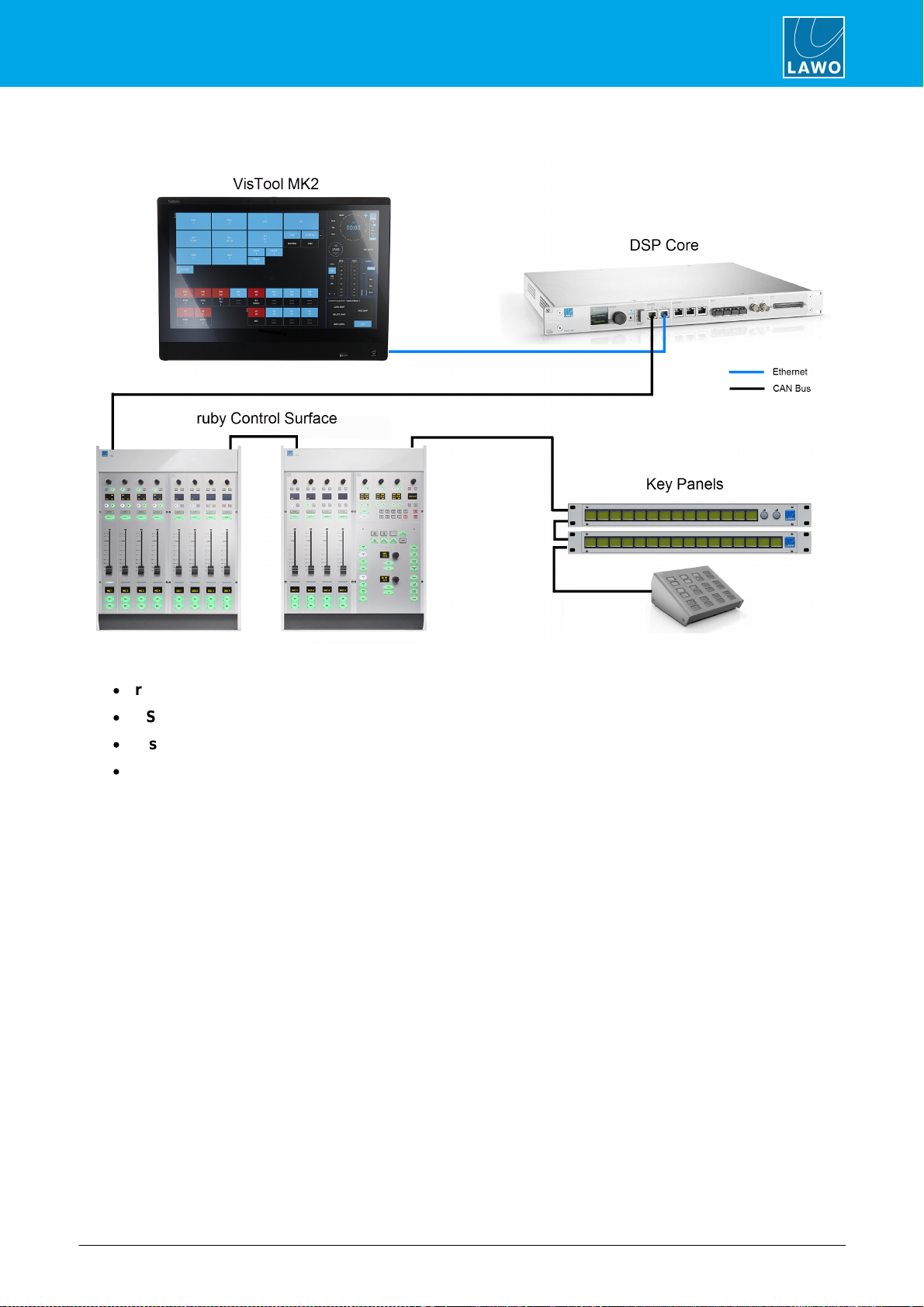
A complete system consists of up to four components:
·
ruby Control Surface (essential) – available in single or split-frame configurations.
·
DSP Core (essential) – all audio interfacing, routing, control and signal processing.
·
VisTool MK2 (optional) – runs on an external PC to provide real-time displays and touch-screen control.
·
Key Panels (optional) – a range of panels offering additional keys and talkback control.
This document describes the ruby control surface.
For more information on other components, such as the DSP Core or VisTool MK2, please refer to the manuals
for those products.
ruby User ManualVersion: 6.6.0/18/78
3. The Hardware
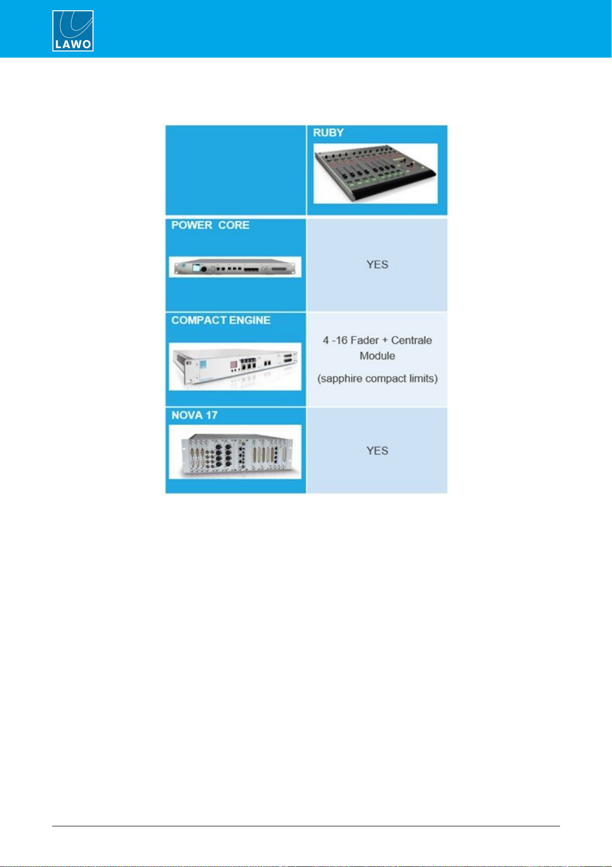
3.2 DSP Core Compatibility
The ruby control surface is compatible with the following DSP Core products:

ruby User Manual Version: 6.6.0/1 9/78
3. The Hardware
3.3 Controls Overview
Each control surface consists of at least one Fader Module (with 4 fader strips) and one Central Module (running
in full mode).
Some of the control functionality is fixed (system-defined), while some is programmable by the configuration.
3.3.1 Fader Module (954/45)
Fader Module
Each Fader Module provides four identical fader strips, each with an ACCESS key, 100mm motorised fader,
backlight and label display.
The upper section includes a rotary control and four small MF Keys (1, 1a, 2, 2b). Their functions are labeled by
the OLED displays.
There are then three large MF Keys (3, 4, 5) with foil-printed labels.
All MF Keys are defined by the configuration.
ruby User ManualVersion: 6.6.0/110/78
3. The Hardware
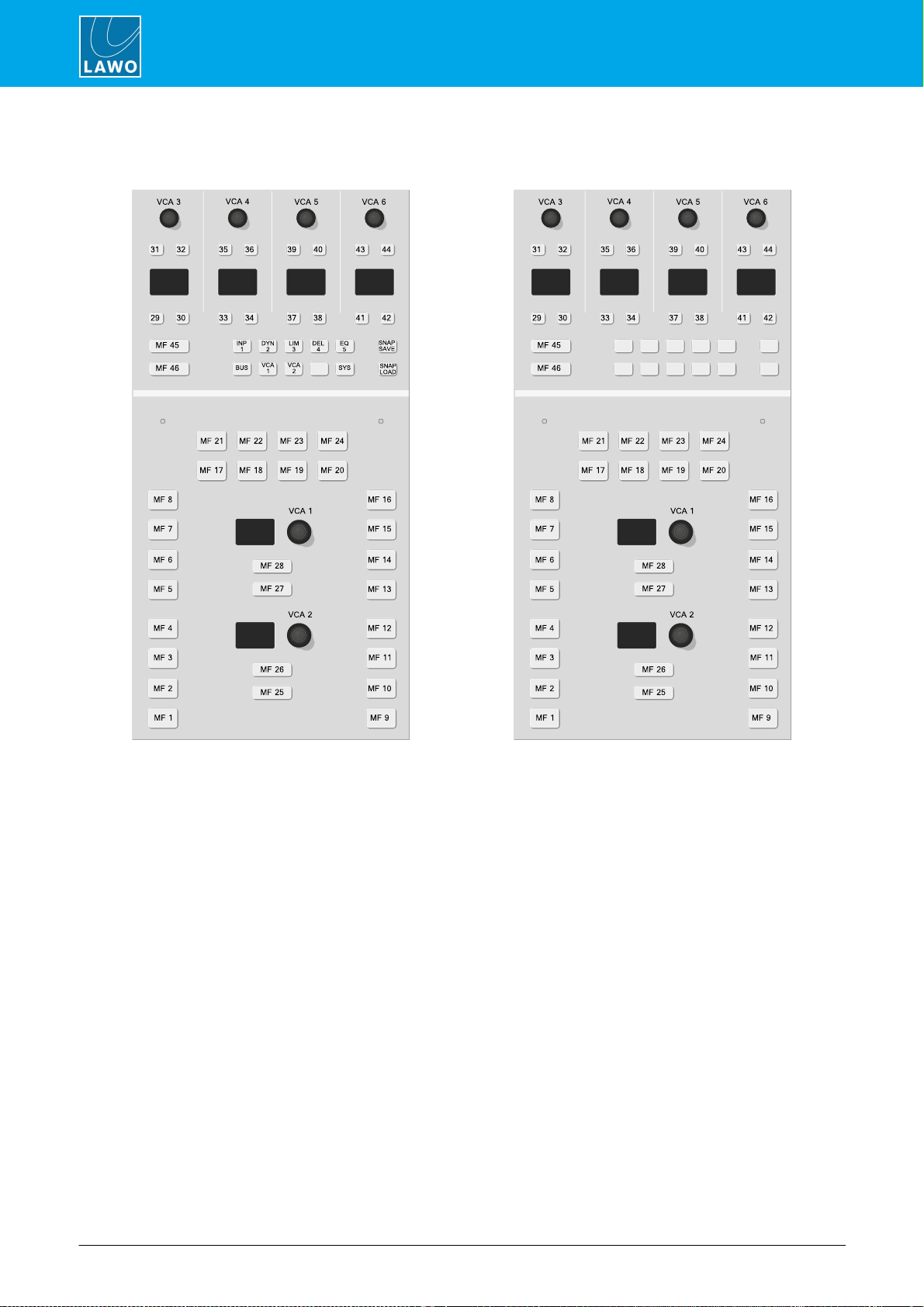
3.3.2 Central Module (954/50)
Central Module (full mode)
Central Module (monitor mode)
Central Module (full mode)
The upper section includes four sets of rotary encoders and small MF Keys which interact with the 12 Function
Buttons: INP, DYN,LIM, etc. Their functions are labeled by the OLED displays. When none of the Function
Buttons are active, the controls are defined by the configuration (MF Keys 29 to 42 and VCAs 3 to 6). When a
Function Button is pressed, then the controls provide DSP parameter control, bus assign, system options and
snapshots. To the left are two large MF Keys (45 & 46) with foil-printed labels.
In the lower section are more large MF Keys (1 to 28) with foil-printed labels, and two rotary encoders (VCAs1,
2) which are labeled by the displays.
All MF Keys and VCAs are defined by the configuration.
Central Modules (monitor mode)
Physically, these modules are identical to the full mode Central Module, but in the upper section the 12 Function
Buttons are NOT supported. This means that there is no access to DSP parameters, bus assign, system options
and snapshots.
All MF Keys and VCAs are defined by the configuration. Note that the 12 Function Buttons cannot be
reprogramed by the configuration and, therefore, will remain blank.

ruby User Manual Version: 6.6.0/1 11/78
3. The Hardware
3.3.3 Programmable Functions
Programmable controls, such as MF Keys and VCA encoders, are defined by the configuration stored on the
DSP Core. They can be edited using the ON-AIR Designer software, allowing you to change the operation as
required.
In most cases, the large MF Keys are labeled by foil-printed labels and, by default, the control surface ships with
the labels for the standard template functions. If you change the MF Key functionality, then you will need to
exchange the foil-printed labels. Printed sheets with the most common labels are included with each control
surface frame.
ruby User ManualVersion: 6.6.0/112/78
3. The Hardware
3.4 Control Surface Variants
8-fader single frame
12-fader split-frame
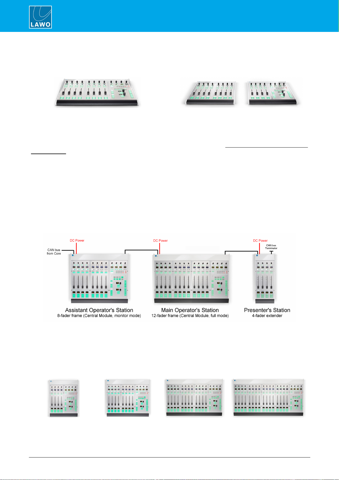
ruby can exist as a single or multi-frame control surface.
A choice of four main and five extender frames are available. Frames can be combined to increase the fader
count or create a split-frame surface.
In total, the control surface can include any number of frames as long as the maximum number of faders does
not exceed 60.
When connected to a standard DSP Core, the control surface must include a Central Module but this can exist
only once. Thus, any additional Central Modules run in "monitor mode". In this instance, the surface supports
up to 60 faders, a single Central Module (full mode) and up to 6 Central Modules (monitor mode).
If the DSP Core is a Power Core Max, then up to four full mode Central Modules are supported. In this
instance, the surface supports up to 60 faders plus any of the following full/monitor mode Central Module
combinations: 4+3; 3+4, 2+5; 1+6.
Each frame connects to the DSP Core via CAN bus, and is powered from its own 12V DC power supply
(included). All frames include CAN IN and CAN OUT connectors for easy daisy-chaining. In each case, the
CAN bus address of a module defines its functionality. Thus, frames can be wired in any order.
Split-frame Example
3.4.1 Main Frame Layouts
Each of the main frame layouts includes a Central Module.
4-fader
8-fader
12-fader
16-fader

ruby User Manual Version: 6.6.0/1 13/78
3. The Hardware
3.4.2 Extender Frame Layouts
The extender frames can be added to increase the fader count or create a split surface.
4-fader extender
8-fader extender
12-fader extender
16-fader extender
Central Module
ext.
3.4.3 Placement Options
Each frame is available in one of three versions to provide different placement options. The version must be
specified at the time of ordering; there is no possibility to convert the frame later.
Table Top
Countersunk
Countersunk Short
The differences in construction are:
·
Table Top - designed for table-top placement. This version includes a leather front buffer and stylish
side/rear profiles.
·
Countersunk - designed to fit flush within your studio furniture. This version comes with different front,
rear and side profiles.
·
Countersunk Short - the same as Countersunk but with shorter side profiles and no upper cover plate
to hide the cables (i.e. the rear panel connectors will be visible).
Table Top Surface (rear view)

ruby User Manual Version: 6.6.0/1 15/78
4. Installation
4.1 Packing List
Each control surface frame ships with the following additional items:
·
1 xexternal 12V DC power supply - to power the frame.
·
1 x2mIEC power cable (country-specific) - to connect mains to the 12V DC power supply.
·
1 x3mRJ45 cable - to connect the CAN bus fromthe surface to the DSP Core or another frame.
·
Printed sheets with "OFF" key foil printed labels (required for Button Start consoles only) - to re-label
the fader strip MF Keys.
If the surface consists of multiple frames, then you will receive one set of accessories per frame (as every
frame requires its own power, CANbus and MF Key labels).

ruby User ManualVersion: 6.6.0/116/78
4. Installation
4.2 Preparation
A single control surface can consist of one or more frames.
Unpacking
Each frame is delivered in its own box with all included accessories.
Please check the contents of the shipping boxes, and in the event of any transport damage, contact your local
Lawo representative or email support@lawo.com. A list of serial numbers for all components is included with the
shipment. Please keep this list for your records.
Dimensions and Weight
The dimensions and weight of the frame depend on its size and version: table-top, countersunk or countersunk
short. Drawings for all frame variants are available fromthe Downloads area at www.lawo.com (after Login).
Temperature and Cooling
The control surface is designed for normal studio installation and needs no special air conditioning.
Power Consumption & Electrical Voltage
Please see the 12V DC Power Supply appendix.

ruby User Manual Version: 6.6.0/1 17/78
4. Installation
4.3 Installing Countersunk Frames
Countersunk
Countersunk Short
These consoles are optimized for easy countersunk mounting.
The frame has rounded-off edges so that it will fit smoothly into holes cut by a wood milling machine.
For the countersunk (regular) version, all cables can be hidden in the cable tray and connected to the console
inlets fromthe open underside of the tray.
For the countersunk short version, the table must be designed to provide a small opening in order to properly
cable the device.
All countersunk frames have flat side parts without edges. Therefore, the installer must provide some kind of
support onto which the surface will rest.
Please see the dimension drawings for details.

ruby User ManualVersion: 6.6.0/118/78
4. Installation
4.4 Exchanging the MF Key Labels
The functions of the MF Keys are defined by the ON-AIR Designer configuration. Printed sheets with the most
common labels are shipped with each frame.
To replace a label:
1. First remove the button cap.
It helps to use a small screwdriver to lift up the button cap (as the caps are recessed). However, you must take
care not to scratch the surface.
2. Insert the foil plate between the button body and the transparent button cap.
3. Fasten the button cap back onto the button body by pressing it!
The photos beloware taken from a ruby surface, but the procedure is identical for crystal and sapphire.
Remove Button Cap
Insert Printed Foil
Label Exchange Complete

ruby User Manual Version: 6.6.0/1 19/78
4. Installation
4.5 Grounding & Power
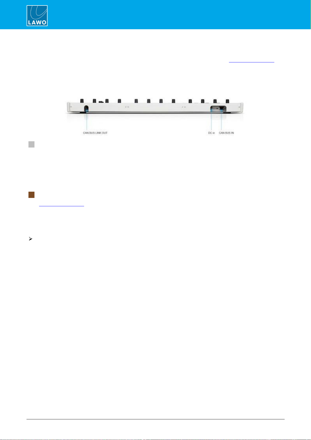
8-fader ruby Surface (rear view)
4.5.1 Grounding
Although operator protection is guaranteed, it is best to establish an additional ground for EMC reasons. On the
control surface, a grounding screwis provided beside the CAN bus connector:
1. Use the M4x8 CASE screwto fasten the grounding cable to the housing.
Each control surface frame must be on the same potential as all other system devices.
For Scandinavian countries, ALWAYS use a grounded mains connection, to prevent the device from being
grounded through Ethernet or other signal connections.
4.5.2 Power
The control surface is powered by its own external 12V DC power supply (955/50-80). This is an identical
supply to the one used by Power Core. The PSU is delivered with its own IEC power cable (country-specific).
For dimensions, weight and electrical specification, see the 12V DC Power Supply appendix.
Ø
To connect DC power to the surface:
1.Connect the 12V DC power supply to the DC IN connector on the rear panel.
2.Using the IEC cable provided, connect your AC mains to the PSU.
The device MUST be connected to the mains using the power cable supplied with the system.
The surface has no on/off switch and starts automatically when power is applied.
ruby User ManualVersion: 6.6.0/120/78
4. Installation
4.6 Wiring
Each control surface frame requires two connections: power and CAN bus. Please see Connector Pin-Outs for
pinning information.
All connectors are positioned on the rear panel, and so you must make sure that these are accessible. In the
table-top and countersunk versions, the cable tray has an open underside and rear access holes:
Table Top Surface (rear view)
1 CAN Bus (CAT 5e)
The CAN ports connect the control surface to the DSP Core and any extenders or key panels.
All CAN bus connections must be point-to-point; a switch or hub is not allowed. Use a standard (straight 1:1)
network cable: STP-CAT 5e with RJ45 connectors. Every frame is delivered with a suitable cable.
The maximumlength of the CAN bus connection is 60 meters.
The CAN bus can be hot-plugged and so the cabling can be performed while the frames are powered.
2 DC In
See Grounding & Power.
4.6.1 CAN Bus Cabling
Ø
To connect a single frame:
1.Connect the DSP Core's CAN connector directly to the control surface CAN BUS IN.
2.Fit the CAN bus terminator supplied with the system to the CAN BUS LINK OUT.
Other manuals for ruby
1
This manual suits for next models
2
Table of contents
Other LAWO Music Mixer manuals


Popular Music Mixer manuals by other brands

Precor
Precor Experience P82 Getting started guide

Pioneer
Pioneer DJM-900SRT operating instructions

Microsoft
Microsoft XBOX user guide

Etabeta electronics
Etabeta electronics NT Series operating instructions

Roland
Roland Edirol M-16DX Workshop guide

American Audio
American Audio 14MXR User guide and reference manual


