CONTENTS
..................................
MOTORCYCLE SAFE RIDING
2
Safe Riding Rules
.........................................................................
2
...........................................................................
Protective Cloths 2
Refitting ......................................................................................2
Loading and Accessories
..............................................................
3
DESCRlPTION
...................................................................
3
................................................................................
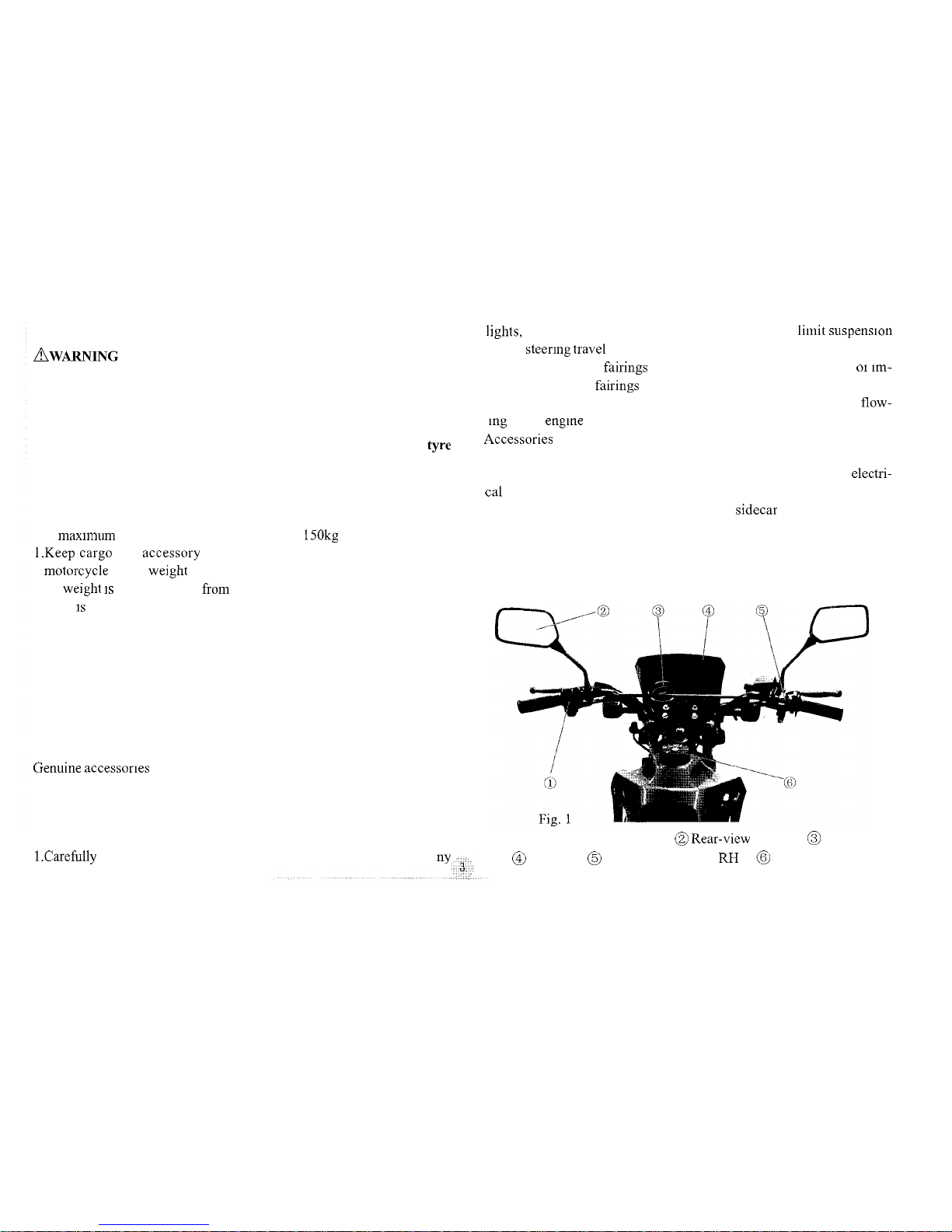
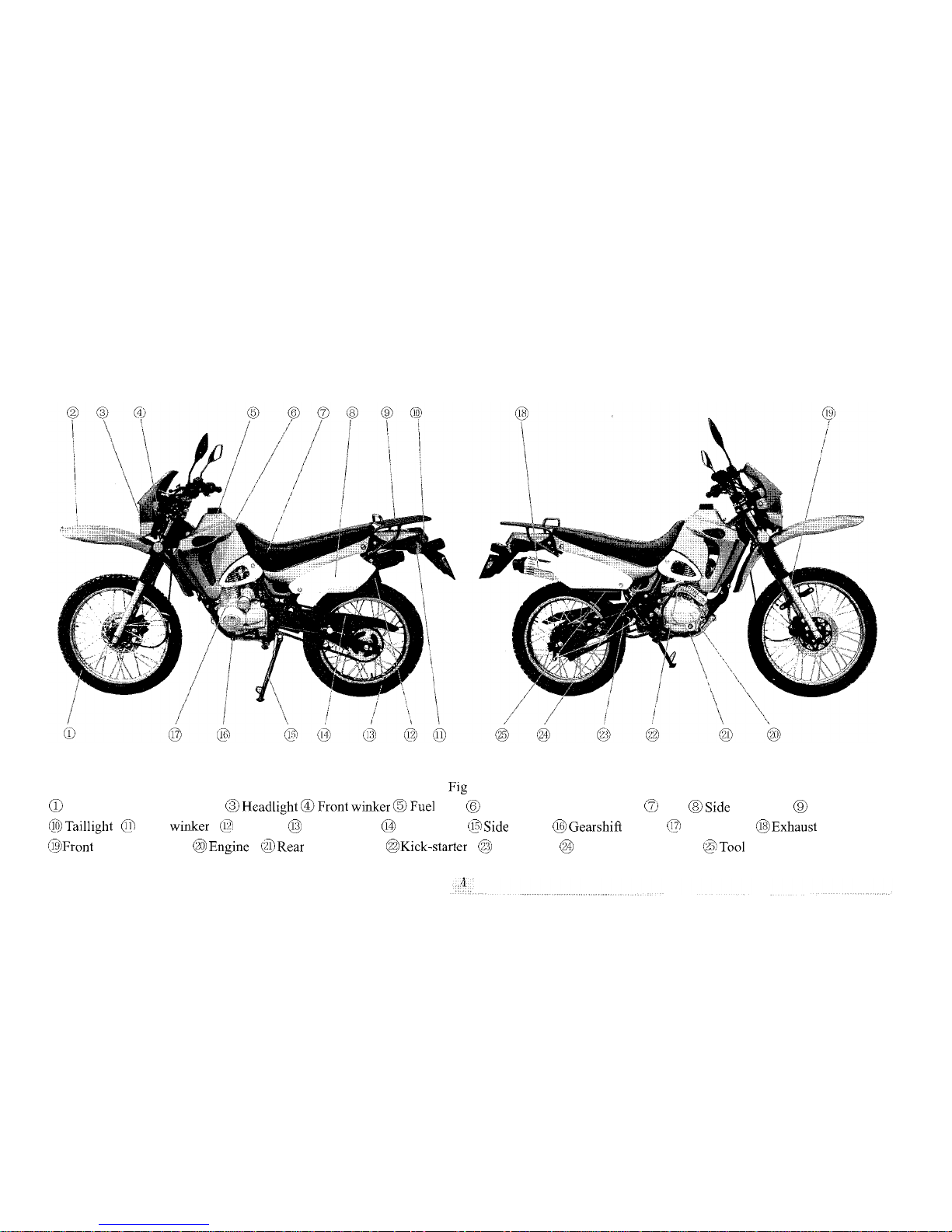
Parts Location 3
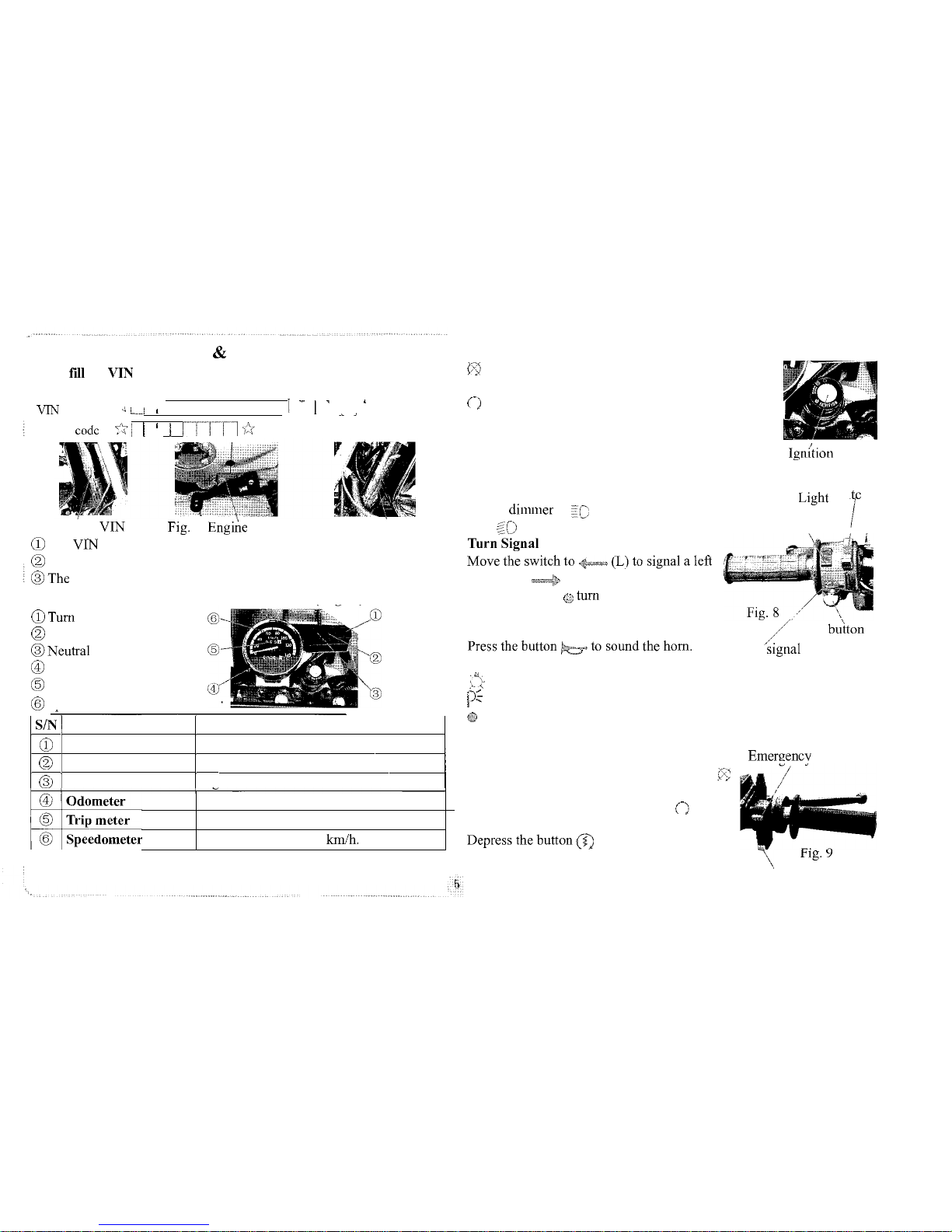
VIN
Record
...................................................................................
5
............................................................
Instruments and Indicators 5
...............................................................................
Ignition Switch 5
................................................................
Left Handlebar Controls 5
Right Handlebar Controls.........................................................5
........................................................................
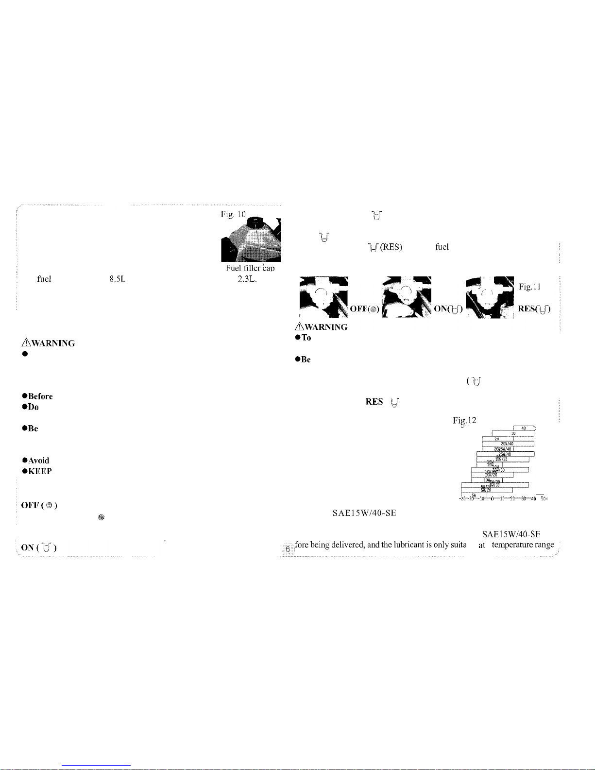
Fuel and Fuel Tank 5
Fuel Cock
......................................................................................
6
Lubricating Oil
..............................................................................
6
Tyres
..............................................................................................
7
.........................................................
OPERATIONGUIDE
7
........................................................................
Pre
-
ride Inspection 7
........................................................................
Starting the Engine
8
.
.
....................................................................................
Brealung-~n
8
Riding
............................................................................................
8
Parking
...........................................................................................
9
..................................................................
MAINTENANCE
9
...................................................................
Maintenance Schedule 9
..........................................................................................Tool Kit 10
...........................................
Check and Change of Lubricating Oil 10
.....................................................................................Spark Plug 11
...........................................................
Clear away Deposit Carbon 11
....................................................................................
Air Cleaner 11
..............................................
Check Leaks along Air Supply Line 12
.........................................................................
Throttle Operation 12
......................................................................................
Idle Speed
12
....................................................................
Adjustment of Clutch 12
...................................................................................
Drive Chain 12
....................................................
Check of Front Shock Absorber 13
.....................................................
Check of Rear Shock Absorber 13
........................................
Check and Adjustment of Front Brake 13
.............................................................
Adjustment of Rear Brake 14
Exhaust Muffler
.............................................................................
I5
Battery ...........................................................................................I5
...............................................................................................
Fuse 15
.............................................................................
Troubleshooting 15
.........................................................................................Cleaning 15
................................................................................
Storage Guide
16
...................................................................
Removal from Storage 16
..............................................................
SPECIFICATIONS
17
...................................................
ELECTRlC DIAGRAM
19