R&S EMC32 Installation and operating instructions

EMI Automotive Band
Evaluation
Application Note
Products:
|R&SEMC32
|R&SEMC32-K51
EMI Automotive Band Evaluation
extension is an on-board EMI
measurement sequence in broadband and
communications frequency bands for
automotive and aerospace applications.
This application notes shows how to
configure, run, and automatically
document tests in a sequence coming with
EMC32-K51.
EMI Automotive Band Evaluation
Hartmut A. Maier
07.2014-01.00

Table of Contents
01.00 Rohde & Schwarz EMI Automotive Band Evaluation with R&S©EMC32-K51 –1SP07- 2
Table of Contents
1Overview EMI Automotive Band Evaluation........................ 4
1.1 Test Method ..................................................................................................4
1.2 Standards related to EMI Band Evaluation................................................4
2Configuration of EMI Automotive Band Evaluation Test.... 5
2.1 Populating the Device List ..........................................................................6
2.2 EMI Automotive Test Template Editor explained......................................7
2.2.1 How to open a new EMI Automotive template in the editor.....................8
2.2.2 Configuration of an EMI Automotive radiated test template .................12
2.2.2.1 The upper part of the template editor ......................................................12
2.2.2.2 The middle part of the template editor.....................................................14
2.2.2.3 The lower part of the template editor .......................................................14
3Configuration of Test Cases in the Editor.......................... 15
3.1 Function of the mouse buttons in the editor...........................................15
3.2 Setting in Test Setup tab ...........................................................................16
3.3 Settings in Subrange tab...........................................................................20
3.4 Settings in Graphics tab............................................................................21
3.5 Settings in Data Reduction tab .................................................................22
3.6 Settings in Actions tab ..............................................................................23
3.7 Close the editor and save the template ...................................................24
4Running an EMI Band Evaluation Test............................... 25
4.1 Measurement Mode....................................................................................26
4.1.1 Start a Test..................................................................................................27
4.1.2 Screen elements:........................................................................................28
4.2 Test Control Bar .........................................................................................30
4.3 Test Results................................................................................................34
5Creating Reports.................................................................. 35
6Literature............................................................................... 41
7Additional Information......................................................... 41
7.1 Short history of EMC32-K51......................................................................41
7.2 Switching to Measurement Mode .............................................................41

Overview EMI Automotive Band Evaluation
01.00 Rohde & Schwarz EMI Automotive Band Evaluation with R&S©EMC32-K51 –1SP07- 4
1Overview EMI Automotive Band Evaluation
EMI Automotive is the solution for a special measurement task. EMI disturbance
signals generated from car components have to be measured with on-board
communication antennas in their frequency bands. The frequency bands as well as the
bandwidth of the antennas may overlap in the frequency domain. This short description
shows why the task is not solvable by a standard EMI Scan, EMI Sweep or EMI Auto
Test template.
Sequenced definition of frequency sub ranges in hardware setups and Scan/Sweep
templates cannot overlap. This task is EMC32 Sequencer related.
EMI Automotive Band Evaluation Test Template now is optimized to generate the
particular kind of test demanded by the standards with extreme flexibility in
configuration of the test and the related test report without usage of the EMC32
Sequencer.
EMI Automotive Band Evaluation Test Template
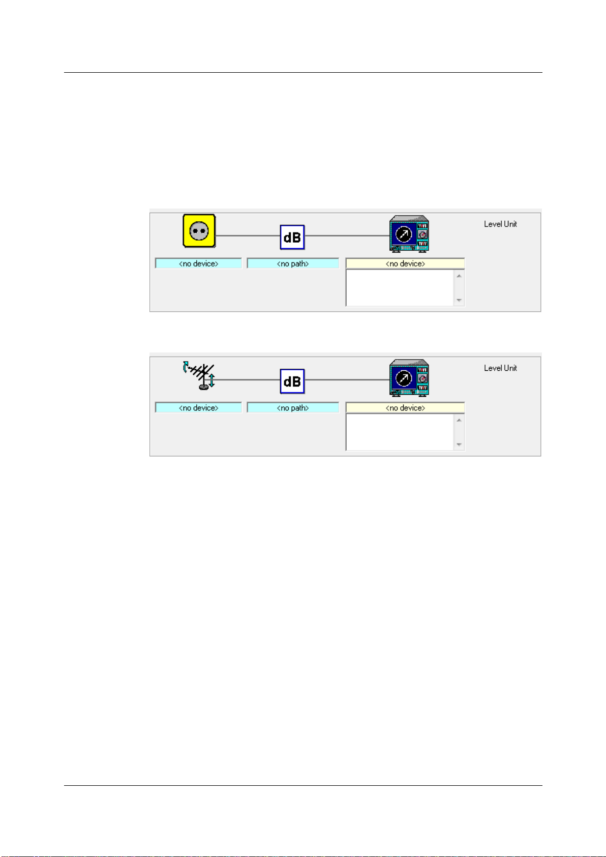
defines sub ranges correspondent to the Band related frequency definition and
uses the appropriate antenna specified for this Band per sub range in a
dedicates hardware setup called Test Setup;
includes a simplified data reduction from auto test to find maxima, and
extends the report to show a separate graphic for each sub range.
The extension “EMI Automotive Band Evaluation”or short “EMI Automotive” therefore
matches two different demands:
it is closely related to automotive and avionic needs, and
it is a kind of sequencer for EMI Tests.
The standard applications are on-board EMI measurement sequences in broadband
and communications frequency bands for automotive and aerospace applications.
1.1 Test Method
The tests are intended to provide protection for receivers installed in a vehicle from
disturbances produced by components/modules in the same vehicle.
The receiver types to be protected are, for example, broadcast receivers (sound and
television), land mobile radio, radio telephone, amateur, citizens' radio, Satellite
Navigation (GPS, etc.) and Bluetooth. The test method is described in CISPR 25 in
chapter 5: “Measurement of emissions received by an antenna on the same vehicle”.
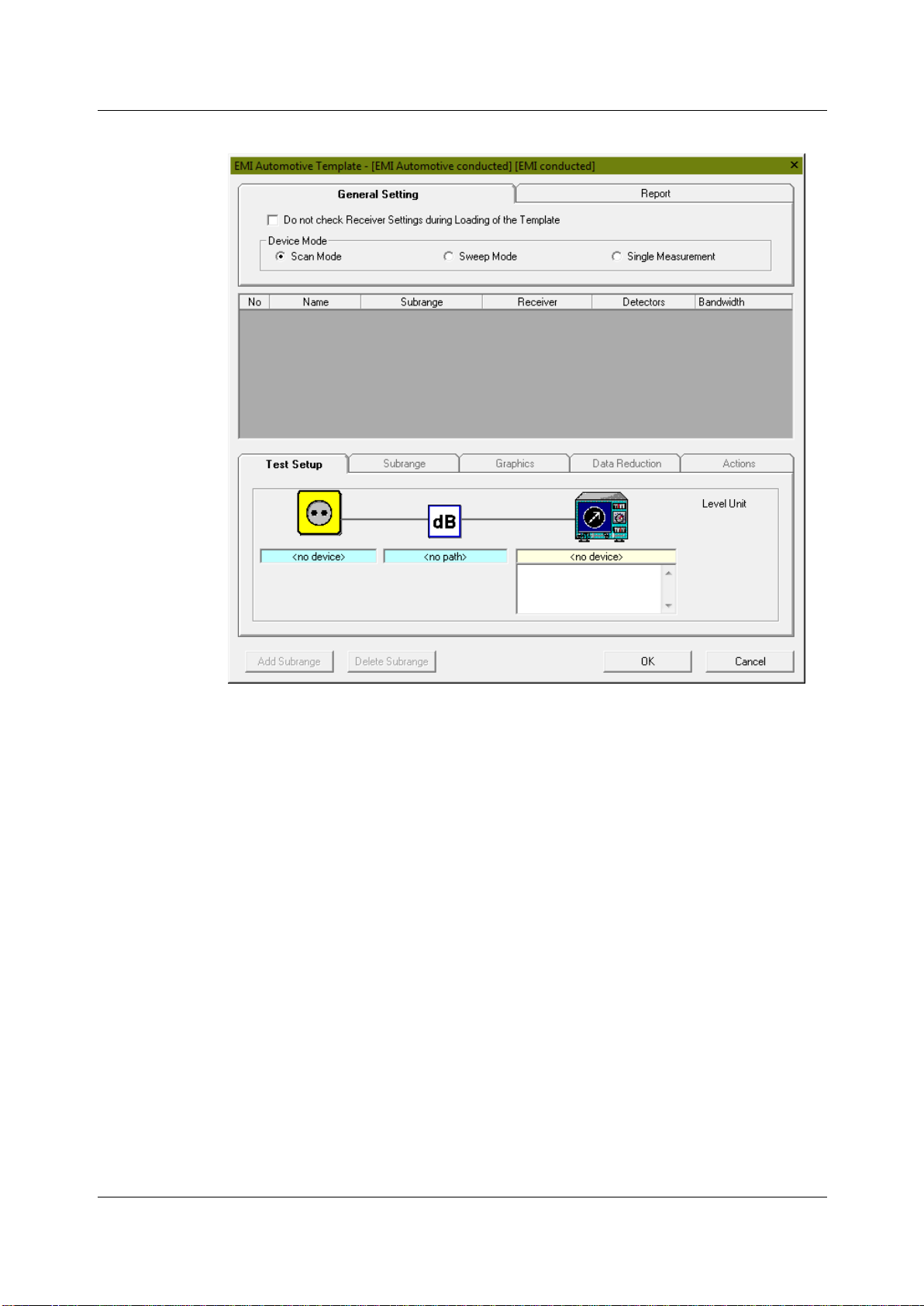
EMI Automotive Test is based on devices in the Device List and an EMI Automotive
Test Template. To achieve a maximum in flexibility the test template editor allows all
kinds of settings and changings which in all other tests are subject to the Hardware-
Setup. EMI Automotive test template works comparable to a test sequence, so it is
possible to do sub ranges with overlapping frequency ranges.
1.2 Standards related to EMI Band Evaluation
CISPR 25: “Vehicles, boats and internal combustion engines –Radio disturbance
characteristics –Limits and methods of measurement for the protection of on-board
receivers”; Edition 3.0 2008-03. CISPR 25 describes the test method and gives a set of
limit lines.

Configuration of EMI Automotive Band Evaluation Test
01.00 Rohde & Schwarz EMI Automotive Band Evaluation with R&S©EMC32-K51 –1SP07- 5
Figure 1: Antenna types
Figure 2: Example for limits of disturbance –Complete vehicle; CISPR 25
EMV-Anforderungen: Erstellt von AUDI, BMW, Daimler (Mercedes-Benz Cars),
Porsche und VW; Edition V1.01: 2009-04-07
GMW3097: General Specification for Electrical / Electronic Components and
Subsystems, Electromagnetic Compatibility (EMC); February 2004
Ford Motor Company, Component and Subsystem, Electromagnetic Compatibility:
Worldwide Requirements and Test Procedures, ES-XW7T-1A278-AC; Date Issued:
October 10 2003
2Configuration of EMI Automotive Band
Evaluation Test
The above referenced standards define several test methods to prove EMC to be
compliant with the standards:
Conducted emissions from components/modules:
Voltage method with Artificial Network (AN-Test)
Capacitive Voltage Method with Capacitive Coupling Clamp (CV-Test)
Current Probe Method (CP-Test, optional)
Radiated emissions from components/modules:
Radiated EMI Measurement of emissions received by an antenna on the
same vehicle
ALSE method, (Absorber Lined Shielded Enclosure)
TEM cell method (TEM-Test, optional)
Stripline method (SL-Test, optional).
Though the test procedures are divided in conducted and radiated emissions we can
concentrate on one test method to show how to use these new kinds of templates. We
select the test procedure for on-board emissions measured with build-in car antennas

Configuration of EMI Automotive Band Evaluation Test
01.00 Rohde & Schwarz EMI Automotive Band Evaluation with R&S©EMC32-K51 –1SP07- 6
(Radiated EMI Measurement of emissions received by an antenna on the same
vehicle, Figure 4). EMC32-K51 provides a conducted and a radiated emission test with
the same icons in the Test Setup as we know from other EMC32 extensions. The
difference is that the hardware setup is not found in the System folder below the sub-
folder Hardware Setups but is integrated into the EMI Automotive Test Template itself.
To configure a test we have to start as usual with the Device List, where we have to
define all devices we need for the new test. As we said we will concentrate on radiated
test
Figure 3: Hardware Setup for conducted EMI Automotive test
Figure 4: Hardware Setup for radiated EMI Automotive test
2.1 Populating the Device List
Radiated EMI Automotive tests need the following devices:
EMI Test Receiver or Spectrum Analyzer
Antennas (given as car antennas or antennas acc. Figure 1)
Switch Unit to connect automatically the band related antenna with the
receiver.
Signal Paths between antennas and the receiver.
The Device List opens via Menu: “Extras > Device List …” or function key “F9”. An
example of a properly filled Device List is shown in Figure 5. Some of the devices need
further configuration. The path configurations of the switch unit have to be done in the
properties of the switch unit in the Device List itself, the settings of the EMI test
receiver are only accessible in the EMI Automotive test template editor.

Configuration of EMI Automotive Band Evaluation Test
01.00 Rohde & Schwarz EMI Automotive Band Evaluation with R&S©EMC32-K51 –1SP07- 7
Figure 5: Device List with example devices used in this App Note
The switch unit (Figure 6) should have all paths needed prepared It depends on the
switch unit whether the user can edit the paths directly or he has to import them, like
OSP. After that we can use them in the hardware setup placed behind the tab “Test
Setup” of the EMI Automotive template editor.
Figure 6: OSP with settings for paths as an example for a switch unit
2.2 EMI Automotive Test Template Editor explained
In order to create a new test case a Template Editor shall be configured according to
the test requirement.

Configuration of EMI Automotive Band Evaluation Test
01.00 Rohde & Schwarz EMI Automotive Band Evaluation with R&S©EMC32-K51 –1SP07- 8
2.2.1 How to open a new EMI Automotive template in the editor
Follow the steps mentioned below in order to create a new EMI Automotive Test
Template.
Open an existing EMI Automotive Template Editor via the EMC32 file explorer. i.e.
System Folder >> Test Templates >> EMI Automotive:
Figure 7: A mouse click on an existing file open the template editor with this EMI
Automotive Test Template
Or create a new template by either of the following steps:
1. Create a template from the main template folder “Test Templates” in Explorer,
this is the only way to create template if the sub folder “EMI Automotive” exists
not yet (top of Figure 8).
2. Create a template from the sub template folder “EMI Automotive” in Explorer
(buttom of Figure 8).

Configuration of EMI Automotive Band Evaluation Test
01.00 Rohde & Schwarz EMI Automotive Band Evaluation with R&S©EMC32-K51 –1SP07- 9
Figure 8: Two possibilities to create a new empty test template
3. Creating template from the main Menu Tool Bar
Creating template from the main Toolbar
Figure 9: Generation a new template via icon "Test Template new/open ..."
After following the above steps a Template Editor window will be opened.

Configuration of EMI Automotive Band Evaluation Test
01.00 Rohde & Schwarz EMI Automotive Band Evaluation with R&S©EMC32-K51 –1SP07- 10
Figure 10: EMI Automotive conducted Test Template Editor

Configuration of EMI Automotive Band Evaluation Test
01.00 Rohde & Schwarz EMI Automotive Band Evaluation with R&S©EMC32-K51 –1SP07- 11
Figure 11: EMI Automotive radiated Test Template Editor

Configuration of EMI Automotive Band Evaluation Test
01.00 Rohde & Schwarz EMI Automotive Band Evaluation with R&S©EMC32-K51 –1SP07- 12
2.2.2 Configuration of an EMI Automotive radiated test template
Figure 12: The three parts of the Template editor
2.2.2.1 The upper part of the template editor
The upper part contains a tab structure in which the general settings, valid for the
whole frequency range, that means for all defined sub-ranges are done. This part
consists of two tabs; General Settings and Report.
Figure 13: General settings for all sub-ranges listed in the middle part
In the General Settings tab (Table 2-1) Receiver Check and Device Mode can be
defined. Never change the Device Mode in a given Template, otherwise all sub ranges
in the middle part of the template will be deleted. The template offers three device
modes but one of them, the “Single Measurement” mode is very specific, it is a
customer solution which description is not part of this application note.

Configuration of EMI Automotive Band Evaluation Test
01.00 Rohde & Schwarz EMI Automotive Band Evaluation with R&S©EMC32-K51 –1SP07- 13
Table 2-1: General Settings
Receiver Check
If untagged the Receiver Settings will be checked during
Loading of the Template. This improves the loading speed
but reduces the security.
Device Mode
Here the operating mode of the selected measurement
device "Test Receiver" or "Spectrum Analyzer" is chosen:
Scan Mode: In all sub-ranges the receiver is in Test
Receiver Mode
Sweep Mode: In all sub-ranges the receiver is in Spectrum
Analyzer Mode
Single measurement: This is a customer specific mode,
which expects additional requirements (customer specific
devices and / or actions referencing the frequency list) In
this mode the frequency steps are not defined by the
receiver device (like a scan mode) but by an additional
frequency list, that is not referenced in the template itself.
One measurement value will be done for every frequency of
the frequency list. In the case there is no frequency list
given this mode works like Scan Mode.
The next tab allows some setting for the report.
Figure 14: Report settings
Detailed setting like configuration of content and design are possible in the report
generator, which is described later.
Table 2-2: Report settings
EUT Information
An EUT Information file can be referenced and so included
into the Report.
Visible Columns in
the Report
The drop down list allows to select and de-select columns
of the result tables in the report. Only checked columns will
be shown.
Report Settings
A click on this icon pops up the standard setting for reports

Configuration of EMI Automotive Band Evaluation Test
01.00 Rohde & Schwarz EMI Automotive Band Evaluation with R&S©EMC32-K51 –1SP07- 14
2.2.2.2 The middle part of the template editor
The middle part contains a table, which gives an overview over all defined sub-ranges
for the EMI Automotive measurement. It is used for displaying a list of sub-ranges. The
settings of the currently selected (active) sub-range in the sub-range list can be
changed in the lower part of the editor.
Figure 15: The pop-up menu and the two buttons allow basic changes
2.2.2.3 The lower part of the template editor
The lower part is the most important one and consists of five tabs: Test Setup, Sub-
ranges, Graphics, Data Reduction and Actions. The parameters for each band related
test (here: sub-range) need to be configured with appropriate setting in all five tabs as
required by the test case.
How to configure the test cases in the lower part of the template editor is topic of
chapter 3.

Configuration of Test Cases in the Editor
01.00 Rohde & Schwarz EMI Automotive Band Evaluation with R&S©EMC32-K51 –1SP07- 15
3Configuration of Test Cases in the Editor
Now we will do all the settings in the lower part of the EMI Automotive Test Template
editor which define an individual test case. The tab structure in the lower part of the
editor is used to display the settings of the currently selected (active) sub range in the
sub range list.
The setup shown in the Test Setup shall be configured prior to the other tabs of this
sub range.
In the Test Setup tab, the following can be defined in sequence:
Define the Transducer from the available list
Define the appropriate Signal Path
Define the Receiver and it's parameters.
3.1 Function of the mouse buttons in the editor
The functionality of the mouse buttons is the same as we know from the Hardware
Setups for other test types.
A right click when the mouse pointer shows a hand symbol on a
device icon opens a selection of all available devices. The currently selected device is
marked with a tick.
A left click when the mouse pointer shows a hand symbol on the
icon opens an editor window with the properties of the device.
Stopping mouse movement in a text box when the mouse pointer
forms an insert symbol shows a pop-up with the full content of the parameter set of the
device.
The following procedure can be used to configure the device. A device is displayed by
means of an icon and a text box containing the selected device's name. If the device
has to be programmed in the context of the template, the mouse pointer changes when
passing over the device icon and a corresponding help text ("Tip Tool Text") appears
below the mouse pointer.
Clicking with the left mouse button on the icon at this point will open the device specific
Settings Dialog. Finally, closing the Settings Dialog with OK will show a summary of
the settings in the text box below the device icon. When opening the template editor
again later on, the fact that such a settings summary text is displayed will proof that
valid device settings have already been defined.

Configuration of Test Cases in the Editor
01.00 Rohde & Schwarz EMI Automotive Band Evaluation with R&S©EMC32-K51 –1SP07- 17
Table 3-1: Icons of the Test Setup tab
Transducer
Right click:
Available are all transducer and antenna devices
depending whether this is a conducted or
radiated measure.
Note: the antenna does not support polarization
settings.
Left click:
The properties editor of the transducer pops up,
the dedicated dialogs are shown in Figure 18
SignalPath
Right click:
The name of the SignalPath will be automatically
generated after choosing both a transducer and
a receiver by right-clicks of the mouse.
Alternatively an existing signal path may be
selected.Left click:
The properties editor of the SignalPath pops up
(Figure 19).
Receiver
Receiver parameters can't be configured before
defining the other devices). After selecting the
receiver, the parameters (e.g. IF BW, step
size...) of the receiver can be set here by clicking
the mouse button on the receiver.Right click:
From the pop up list of receivers an appropriate
device is chosen.Left click:
The properties of the receiver has to be set as
shown in Figure 20.
This read only icon shows the Level Unit, the
unit of the measured signal. The setting is done
in Measurement Correction tab in Figure 18

Configuration of Test Cases in the Editor
01.00 Rohde & Schwarz EMI Automotive Band Evaluation with R&S©EMC32-K51 –1SP07- 18
Figure 18: Three dialogs to define the antenna(s)
Dialog defining the switched signal path from test receiver to the antenna.

Configuration of Test Cases in the Editor
01.00 Rohde & Schwarz EMI Automotive Band Evaluation with R&S©EMC32-K51 –1SP07- 19
Figure 19: Dialog to define the signal path
Figure 20: Receiver settings according to the chosen mode

Configuration of Test Cases in the Editor
01.00 Rohde & Schwarz EMI Automotive Band Evaluation with R&S©EMC32-K51 –1SP07- 20
3.3 Settings in Subrange tab
In the Subrange tab, the following parameters can be set:
Figure 21: Settings of the Subrange tab
Table 3-2: Setting in the Subrange tab
Frequency
Start and stop frequency for this subrange. The
stop frequency must always be higher than the
start frequency.
Properties
Subrange Name:
Individual name can be defined here for the
subrange or band
Enabled:
Checked: Measurement defined in this
subrange will be carried out during test
run,
Unchecked: Measurement defined in this
subrange will be skipped during test run
Detectors
If one or both detectors should be used for this
subrange. If only one detector is selected it will
be used for this subrange automatically.
Detector
Mode
Allows to check ClearWrite and / or Maxhold
ClearWrite: New measurement value
overwrites the old one, and
MaxHold: New measurement value is
stored if it is higher than the old one
This manual suits for next models
1
Table of contents