Rane FME 15 Service manual

OPERATING/SERVICEMANUAL FME15
EQUALIZER
QUICKSTART
Formanyofyou,readinganowner’s manual isaboutasinsultingasusingtraining wheels
onyourfirsttwo-wheeler.WethereforeofferthefollowingQuickStartsectionwhichoutlines
thebasicsof theFME15 sobriefly it countsonly asfamiliarizationmaterial, nottraining.
Usingthe FME15 in aninsert loopof amixer isextremely easy.Simply connect them
togetherusinga single stereocable(¼" TRS)betweenthe mixer’sinsertloop and theFME
15’sPATCHI/O jack.Thisjackiswiredforthetip=send,ring=returnconventionused by
mixermanufacturers.
Anyonefamiliarwithother graphicequalizerswillfind thisonejustas familiar. Oneword
ofcaution:theboost/cut RANGE switchdrasticallychangesthe impactofagiven filter.Be
careful.
SettheINandOUTGAIN controls tothesamephysical positions forunitygain through
theequalizer.Thatis,movingbothsliderhandlestogether(keepingthemaligned)always
maintainsoverallunitygainfrominputtooutput.Manystrangegainstructureconditionsmay
behandled withthese controls.See theOperating Instructionson the back page for more
information.Mostapplicationsrequireonlyafew dB ofboostorcut.Startwiththe RANGE
switchinthe±6dB position,andincreaseto±12dBonly ifnecessary. Settingcurves isas easy
asitison allRanegraphicsthanks toouruniqueinterpolating constant-Q circuitry.Formore
informationonsettingupyourcurvescorrectly,again,seethebackpage.
NEVERCONNECTANYTHINGEXCEPTANAPPROVEDRANEPOWERSUP-
PLYTOTHEREDTHINGTHATLOOKSLIKEATELEPHONEJACKONTHE
REAROF THE FME 15. This is an ACinput and requiresspecial attentionif you donot have
anoperationalpowersupplyEXACTLY liketheonethatwasoriginallypackedwithyourunit.
Seethefullexplanationofthepowersupplyrequirementselsewhereinthismanual.
SYSTEMCONNECTION
WhenfirstconnectingtheFME15toothercomponents,
leavethe powersupply for last.Thisgives youa chanceto
makemistakesandcorrectthemwithoutdamagingyour
fragilespeakers,earsandnerves.
INPUTS. Allthree Inputs are wired inparallel and are
activelybalanced(allFlexmodulesfeaturetrueinstrumenta-
tionamplifierbalancedinputs).Eachworksequallywell.
Choosestrictlyfromafavoritehardwarepoint-of-view,there
willbenoperformancetrade-offs.Thewiringconvention
adherestoAmerican,BritishandInternationalstandardsof
pin 2, “+”, ortip being hot;pin 3, “–”, or ring being return;
andpin1,COMMONGND,orsleevebeingsignalground.
Unbalancedoperationinvolvesusingonlypin2,“+”,ortipas
signal;and pin1, COMMONGND, or sleeve as ground.It is
notnecessary toshort anyterminals or pins to anyothers. Due
tothe trueinstrumentation nature ofthe inputs,there is no
gain reduction if pin 3, or “–”, is left open; however, if pin 3
getsshorted, itwon’t hurt anythingeither. Usepin 1, the
shell,orthe COMMONGNDpoint ontheterminal stripfor
shieldground.(SeeRaneNote110forfurtherinformation).
OUTPUTS.TheFME15’sOutputsmimictheInputs.
Truebalancedoutputinterconnectiononlyrequirestheuseof
pin 2, “+”, or tip; and pin 3, “–”,or ring for signaltransmis-
sion.It does notrequire pin 1,or signal ground.All the signal
existsbetweenthe twobalancedleads; groundisnot in-
volved.Ground isused only for
shielding.Ifunbalancedoutputis
yourpreference, use pin2, “+”, or
tipassignal; andpin1,COMMON
GND,or sleeve as return.Leave
pin 3, “–”, or ring open. Again,
have a look at Rane Note 110 for
moredetail.
EXPANDING.Expandingand/
ordaisychainingtheinputsandoutputsnormallyusesthe¼"
jacks.Multipleparallelconnectorsallowusinganotheroutput
todriveasecondprocessororamplifierwithoutspecial
cabling.
PATCHI/O.ThePATCHI/O(Input/Output)jackmakes
connectiontomixereffectsloopinsertpointsverysimple.
Justconnectashieldedstereotip-ring-sleeve(TRS)cable
betweenthe FME15’s PATCHI/O jackand theTRS effects
loopinserton yourconsole.(Your mixermustuse the
tip=send,ring=returneffectsloopwiringconvention.)
SIGNALLEVELS. TheFME15isdesignedforallline-
levelsignals.Signallevelsfrom-10dBVto+4dBuorconsid-
erednormaland withinrange(at least16dBof headroom
existsabovetheselevels).Donotdirectlyconnectmicro-
phonesinto the FME 15. Use a micpreamp first.

FRONTPANELDESCRIPTION
1.MASTEROVERLOADINDICATOR. ThisredOLLEDmonitorstheinput,
outputandallfilterstagesforexcessivesignallevels.Itlightswheneverthese
levelsexceed4dBbelowclipping.Occasionalflickeringisnormal;however,it
shouldnotbeallowedtolightsteadily.
2.OVERALLBYPASSSWITCH&INDICATOR. Thispushbuttonswitch
activatesthe“hard-wire”bypassfunction.Whenpressedintotheengaged
position(red BYPASS LEDon), all threepins of theINPUT connectors are
directlyconnectedtothesamepinsontheOUTPUTconnectors(hard-wired).
EngagingthisswitchconvertstheFME15intoarelativelyexpensivepatchcord,
butonewithprettylights.
3.INPUTANDOUTPUTGAINCONTROLS. Theseslidecontrolssettherelative
INand OUT gain structures.The range ofeachcontrol is±12dB;however, note
that they are labelled opposite to each other, i.e., the top of the INcontrolreads
+12dBwhilethetopoftheOUT controlsreads-12dB.Configuredthisway,
whenevertheyaremoved togethertothesame spotstheoverallgain through the
FME15staysatunity.Normallysetthesecontrolsintheircenterdetentpositions.
4.FILTERLEVELCONTROLS. Thesefifteenslidecontrolssettheindividual
levelsoftheinterpolatingconstant-Qfilters.Theirrangeisselectablebetween
±6dB(usebottomor right-handscale)and±12dB (usetoporleft-hand scale). The
groundedcenter-detentdesignoftheseslidersensuresallfiltersare off when
positionedtotheircenters.
5.FILTERRANGESWITCH. Setstheoverallrangeofallslidersbetween±6dB
and±12dB.
6.POWERINDICATOR. ThisyellowLEDlightsanytimeremotepoweris
supplied from either a RS 1 or VC 18 single power supply or FRS 8 or RAP 10
multiplepowersupply(butnot in thepresenceofPopes,Queens andPresidentsas
onemightwellexpect).

REARPANELDESCRIPTION
1.3-pin INPUT Connector. Pin2 ispositive, pin3 isnegative andpin 1 is signal
ground. For unbalanced operation, use pin 2 as hot and pin 1 as return. Do not use
morethan one of theINPUT connectors on the FME 15.
2.INPUTExpandConnector. This¼"TRSconnectorparallelsthe3-pinconnector
describedinitem #1.Tipis positive, Ringisnegative andSleeveis signalground.
3.TerminalStripINPUTandOUTPUT. The“+”,“–”,andCOMMONGND
terminalsof the#6 terminalstrip parallelthe respectivepins in the 3-pin and ¼"
connectors.UsedforprimaryInputsandOutputsoradditionalpatchconnections.
Useonly oneINPUT connector:they do not sum. Youmay usemore thanone
OUTPUTconnectortosplittootherdevices.
4.OUTPUTConnector. This¼"TRSconnectorparallelsthe3-pinconnector
exposedin item #5below. As before,Tip is hot,Ring is notand Sleeve issignal
ground.
5.3-pin OUTPUT Connector. Pin2 ispositive,pin 3is negative andpin 1issignal
ground.Forunbalancedoperation,donotshortanypinstoanyothers.Active
balancedOutputsoperatedintheunbalancedmodeuse only pin2drivingtheline
andpin 1acting as thereturn. Pin3 should be left disconnected.Grounding pin 3
willnot causeany damage norwill itimpair the sound. It onlycreates extrawork
foryour audio electronsand isunnecessary. Youmay use morethan onetype of
OUTPUTconnectorsimultaneouslytodrivemultipledevices.
6.PATCHI/OConnector. This¼"TRSjackprovidesanunbalanced I(Input)on
itstip andan unbalanced O(Output)on itsring. Designedfor usewith tip=send/
ring=returneffectloopinsertsfoundonmanymixingconsoles.Thisprovidesan
easymeansforpatchingthe FME 15intoeffectloopsas painlesslyaspossible,
usingasingle¼" TRSstereopatchcable. CAUTION:USEEITHERTHEPATCH
I/OORANYOFTHEINPUTANDOUTPUTCONNECTORS—DONOTUSE
BOTHATTHESAMETIME.THESEARENOTSUMMINGINPUTS.ONLY
ONEAT A TIMEMAY BE USED.
7.GROUNDLIFTSwitch. Thisswitchprovidestheabilitytoseparatechassis
groundandsignalground.Normally,thisswitchshould be intheLIFTposition.In
somecircumstances,movingittotheoppositepositioneliminatesstubbornhum
andbuzzproblems.Werealizeascientificexplanationwouldbehelpful,unfortu-
nately science doesn’t have enoughto do with it. Ifyou are temptedto try moving
thisswitch with yourpower amplifiersturned on andup, don'tbe.alwaysturn
youramplifierlevelsdownbeforechangingyourgroundsaroundandthenbring
themup slowly.Put a speakerre-coner outof work today!
8.ChassisGroundPoint. A6-32 screw isusedforchassisgroundingpurposes. See
theCHASSISGROUNDING noteonthelastpagefordetails.
9.RemotePowerSupplyInput. Theunit issuppliedfromthe factorywithaModel
RS1RemotePowerSupplysuitableforconnectiontothisinputjack.Thepower
requirementsoftheunitcallforan18-24volt AC center-tappedtransformeronly.
ITISNOTA TELEPHONEJACK.NEVERUSE APOWERSUPPLYWITH
YOURUNITOTHERTHANTHEONESUPPLIEDORAREPLACEMENT
APPROVEDBYRANECORPORATION.Usinganyothertypeofsupplymay
damagethe unitand voidthe warranty.Two yearsparts andlabor isworth
safeguarding,don’tyouthink?

All features & specifications subject to change without notice. 520-124 JUL95Printed in the U.S.A. on Recycled Paper
©RaneCorporation1080247thAvenueWest,MukilteoWA98275-5098 TEL(206)355-6000 FAX(206)347-7757
OPERATINGINSTRUCTIONS
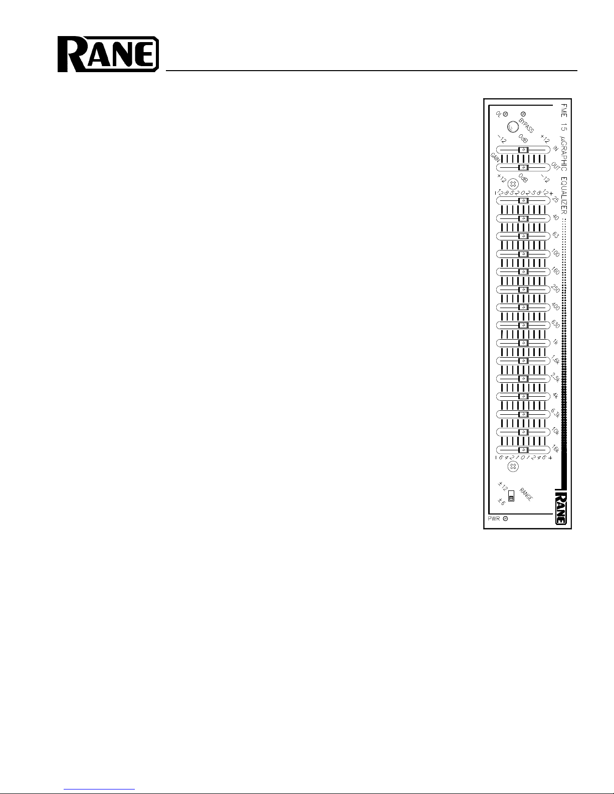
BeforeattemptinganyequalizationofaudiowiththeFME
15,itis importantto optimize theIN andOUTGAIN control
settings.Impropergaindistributionisacommoncauseof
headroomlossandincreasednoiseinaudiosystems.
TheFME15providesyouwithanoverallBYPASS
switch & indicator as well as an OL(overload)LED asuseful
toolsforoptimizingthisgainset-up.TheBYPASSswitchis
usefulformakingquickA-Bcomparisons,i.e.,comparing
equalized(BYPASSout,LEDoff)versusunequalized
(BYPASS in,LEDon)sound. Todothisfreely, without
dangerofsystemdamage,requiresyou set thelevelthrough
theFME 15to approximatelyunity. Failureto doso can
producealarmingresults,whenA-B-ing.
The input and output gain ranges of the FME 15 go from –
12dBto+12dB. TheFME 15isalways unitygain inBypass,
so if you add or reduce gain (beyond EQ make-up gain) the
leveldifferencesbetweenBYPASSin/outcanbestartling.
Thereforeyouwantto settheGAIN controls forequalin/out
loudnesslevels.
Togetstarted,makethefollowinginitialset-upadjust-
ments:
1.BYPASSswitchdepressed(equalsbypassedcondition
equalsred LEDon).
2.BothGAINcontrolscenter-detentpositions.
3.Allslidecontrolscenter-detentpositions(0dBboost/cut).
4.Apply asignal tothe system.
5. Check that the OL indicator is not on.If the OL LED is on,
movebothGAIN controls down justenough foritto go
out.TheFME 15staysunity gainfrominput tooutput
becauseyoukeptbothcontrolsatequalsettings,thus
ensuringthe input isattenuated enoughto keep itout of
overloadand the outputgain is makingup for it.For
optimumnoiseperformancealwaystakeasmuchgainas
possiblethroughtheinputstages,i.e.,positiontheIN
GAINsliderascloseto+12dB(theOUTGAINslider
toward–12dB,keepthemtogether)aspossible.IftheOL
LEDis not on, then leavethe GAIN controls intheir
center-detentpositions.Donotincreasethegainabovethis
pointuntilyoudo enoughcuttingwiththe EQcontrolsto
warrantaddingmake-upgain.
6. Release the BYPASS switch and you are readyto start
equalizingthesystem.
Sinceacousticcompensationandtonecontouringaretwo
of the most common uses for equalization, here are a few
wordsoneach:
ACOUSTICCOMPENSATION. Acousticcompensation
iscontrolled nicely with a device such asthe FME 15. The
bestway to find out whatroom acoustics are doing toyour
soundis to useeither areal time analyzeror computerized
measurementsystemssuchastimedelayspectrometryor
othersimilar devices. Thissort oftest equipment letsyou see
theresponseofthecombinationofroomandsoundsystem
andis theonly accuratemeans availablefor settingup the
FME 15 properly. If you are unable to utilize science in this
way, your ears will have to be the judge.
It is a very good idea to always start the equalization
processwith the filterRANGE switchinthe±6dBposition.It
shouldstaythereunlessyouabsolutelycannotachieveyour
goalany other way.Then and onlythen should yougo for the
±12dBposition.
UsetheBYPASS switchtocompareequalizedwith
unequalizedsound.Comparethetwoandsettheequalizeras
bestyoucan usingsourcematerial thatyouare veryfamiliar
with. Try to avoid adding too much low end. This is an area
whereequalizersarefrequentlyabused,causinglotsof
unnecessarystressonamplifiersandspeakers.Thisis
particularlyimportantwhenusinganysortofventedenclo-
surelow frequencydrivers. Toomuch levelapplied toa
wooferbelowthecutofffrequencyofitsenclosurecauses
verylargespeakerexcursionsandveryshortlife.
TONECONTOURING withtheFME15isaccom-
plishedmainly by ear. This you know howto do. Be careful,
though,nottointroduce toomuchboostto theupperbass
area(and the sub-bass area as in thelast paragraph) to prevent
youraudience from calling 911. Be aware thatthe FME 15 is
capableofboostingsignalsupto 12dB—alevelatwhich
greatcareshouldbetakentopreventseismicdisturbances.
IMPORTANTNOTE
CHASSISGROUNDING
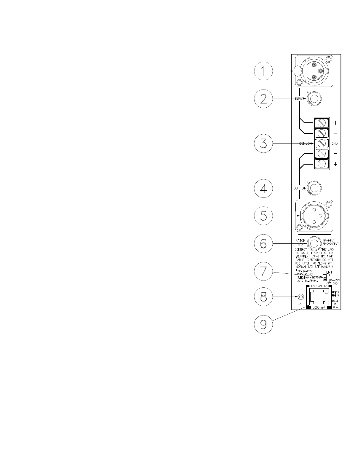
RaneFlexSeriesmodulesaresuppliedwith arear-
mountedground-liftswitch.Theunitisshippedwiththis
switchinthe“grounded”position,tyingcircuitground
tochassis ground. Ifafter hookingup yoursystem it
exhibitsexcessivehumorbuzzing,thereisanincompat-
ibilityinthegroundingconfigurationbetweenunits
somewhere.Yourmission,shouldyouacceptit,isto
discoverhowyourparticularsystemwantstobe
grounded.Herearesomethingstotry:
1.Trycombinationsofliftinggroundsonunitsthat
aresuppliedwithgroundliftswitchesorlinks.
2. If your equipment is in a rack, verify that all
chassisaretied toagood earthground,either through
theline cord grounding pinor the rack screws to another
groundedchassis.
3.Unitswithoutboardpowersuppliesdonotground
thechassisthroughthelinecord. Make surethatthese
unitsaregroundedeithertoanotherchassiswhichis
earthgrounded,ordirectlytothe grounding screwonan
AC outlet cover by means of a wire connected to a screw
onthe chassis with a star washer toguarantee proper
contact.
PleaserefertoRane Note110(suppliedwith your
productand available on requestat no charge if you lost
yourfirstone)forfurtherinformationonsystemground-
ing.
Table of contents
Other Rane Stereo Equalizer manuals
Popular Stereo Equalizer manuals by other brands

Pulsar
Pulsar Pulsar Massive user manual

Coyote Point Systems
Coyote Point Systems Equalizer Installation and administration guide

Altec Lansing
Altec Lansing 1432A SIGNAL PROCESSING Specifications

Audiovox
Audiovox AMP-772CS owner's manual

Z Systems
Z Systems z-q2 Operation manual

Altec Lansing
Altec Lansing 8553B SIGNAL PROCESSING Specifications