Rank Aldis TUTOR II Owner's manual

1AldisTutorIIService©M.Ginda08/02/2008WWW.Karillon.com
SERVICING INFORMATION
RANK ALDIS
TUTOR II
© M.Ginda 08/02/08

2AldisTutorIIService©M.Ginda08/02/2008WWW.Karillon.com
Servicing the Rank Aldis Tutor II effects projector.
This is a short guide on how to service the main component parts of the
projector.
You will need some simple tools to complete the service and some cleaning
solutions.
Tools:
Cross point screwdrivers
Flat blade screwdrivers
Snipe nose pliers
4BA nut spinner
Circlip Pliers (optional)
Cleaning Solutions:
Isopropyl Alcohol or Methylated spirit
General purpose ‘foam cleaner’ or warm soapy water
You will also need a small brush (pastry brush or similar size) and some
cleaning cloths. To clean the lens and heat filters you need a clean, preferably
lint-free cloth.
Before starting, it’s a good idea to wear vinyl or latex gloves, especially if the
projector is exceptionally dirty inside.
Please note that this document is offered as a guide. I do not accept any
responsibility for damage to equipment or persons as a result of actions
advised in this document.

3AldisTutorIIService©M.Ginda08/02/2008WWW.Karillon.com
STEP 1
Disconnect the power from the projector! VERY IMPORTANT
STEP 2
Start by removing the four screws holding the main cover in place, then
remove the cover from the projector body. The handle or carry strap
(dependant on model revision) is part of the cover, do not remove it.
STEP 3
Remove the front gate assembly from the main body by rotating the gate a
little to reveal the four xpoint securing screws. Removing the screws will
release the whole front gate assembly.
Rotate to reveal fixing screws
Remove all four screws,(one
located at each corner).
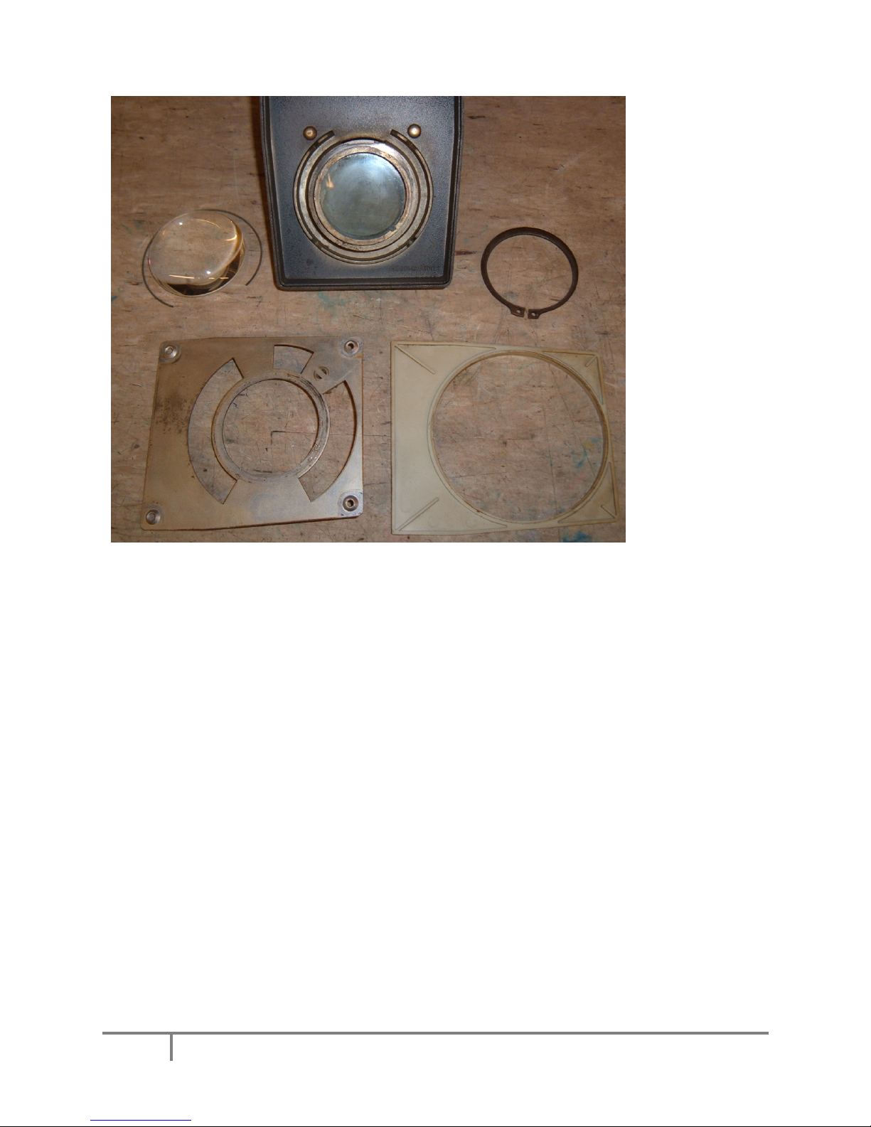
STEP 4
The front gate lens assembly can now be serviced. Start by removing the clip
holding the lens in place (looks like a piece of wire, use a small screwdriver to
lever this out), then carefully remove the lens from the housing.
Be careful not to damage the lens during this operation, and observe that the
lens has the larger domed side toward you.
You now have access to the secondary heat filter. DO NOT attempt to remove
the heat filter unless it is damaged.

4AldisTutorIIService©M.Ginda08/02/2008WWW.Karillon.com
Lens clip
Front Lens
Secondary Heat Filter
STEP 5
Turn over the front gate assembly and using circlip pliers, or a flat blade
screwdriver and snipe nose pliers, carefully remove the large circlip holding
the rotation plate in place.
Circlip Removed

5AldisTutorIIService©M.Ginda08/02/2008WWW.Karillon.com
Once the circlip is removed, the component parts of the gate head assembly
can be separated.
OK now it’s time to clean these parts.
Start by cleaning the metal parts with general cleaning solution, wipe away
any excess and dry. Clean the plastic filler with warm soapy water and dry
thoroughly. Stubborn oily deposits can be removed with spirit or alcohol.
Very carefully clean the lens and the heat filter, first with a small amount of
foam clean or soapy water. Dry thoroughly then clean both parts using some
spirit or alcohol and a clean dry lint free cloth.
Make sure both parts are thoroughly clean, avoid handling the lens with bare
fingers as finger marks if left, will eventually become permanent marks.
Double check the heat filter is clean and dry as you will have limited access
again once the components are re-assembled.

6AldisTutorIIService©M.Ginda08/02/2008WWW.Karillon.com
STEP 6
The gate head assembly can now be re-assembled.
Using a small piece of cloth, lightly oil the rear rotation mount (where the circlip
fits). You can use a standard hinge oil or clean engine oil for this.
Re-assemble the component parts in the reverse order taken for disassembly.
After fitting the lens, place the assembly to one side away from the work area.
STEP 7
Remove the four Lamp House
retaining screws from the front of
the main body.
This will partly release the lamp house assembly from the main body.

7AldisTutorIIService©M.Ginda08/02/2008WWW.Karillon.com
STEP 8
Remove the Lamp House cover, clean this item and place to one side.
If this item has paint damage, rub down and re-paint using a MATT finish black
paint.
Next remove the reflector and condenser lens plates from the lamp housing.
Carefully remove the lamp using a small plastic bag to first cover the lamp. Do
Not touch the lamp with bare fingers, if you do then clean the lamp envelope
with alcohol or spirit.
Primary heat filter
Reflector
Condenser Lens

8AldisTutorIIService©M.Ginda08/02/2008WWW.Karillon.com
Clean the condenser lens in the same manner as in STEP 4.
The reflector is chrome plated steel and should be carefully polished after
cleaning with spirit. Do not scratch the surface.
Access can now be made to the primary heat filter. This should be removed by
rotating the retention clip, and carefully pulling out the glass filter.
Clean the filter in the same manner as used for the lens. Place these items
safely away from the work area until re-assembly.
STEP 9
The lamp housing assembly, the fan unit and the fan unit baffle can now be
removed from the main projector body.
To achieve this, turn the main body on its side.
Remove the screws holding the lamp housing assembly.
Remove the screws holding the fan baffle plate.
Remove the 4BA nuts and bolts retaining the fan unit.

9AldisTutorIIService©M.Ginda08/02/2008WWW.Karillon.com
Lamp Housing screws Fan Baffle Plate screws
FanUnitBolts
NOTE:
The 4BA nuts have washers under them.
First remove the fan baffle plate, take note that the cables to the lamp and fan
pass through a grommet located at the base of this plate. This plate can now
be cleaned.
Now remove the lamp housing and Fan assembly, note that like the fan baffle,
the lamp housing has a cable grommet. Place the items on the bench top and
avoid damage to the cables.
The projector body can now be
cleaned using a brush and then
cleaning solution.
Ensure you dry this area thoroughly.
Avoid getting liquid near the
transformer and lamp holder.

10AldisTutorIIService©M.Ginda08/02/2008WWW.Karillon.com
Visually inspect the lamp holder and replace this if necessary.
STEP 10
Service the Fan unit.
Start by removing the five screws holding the cover plate.
Remove the plate and clean this, taking care not to bend it. The Case part of
the fan assembly is very fragile; take care not to damage it.
Prize off the fan blade from the motor shaft using a large screwdriver (from the
motor side). Now remove the four 4BA nuts retaining the motor and withdraw
the motor from its housing. Clean the housing and plastic fan.
Inspect the housing for damage. If evident glue cracked parts with model glue.
Holes or badly damaged areas can be fixed with epoxy glue.
The Motor can now be serviced.
Remove the four nuts and bolts holding the
rotor.

11AldisTutorIIService©M.Ginda08/02/2008WWW.Karillon.com
Both bearing plates and the rotor can be removed from the armature.
Clean any residue from the bearing plates and the motor spindle. Be careful
not to lose the two fibre washers and the steel shim.
After brushing clean the armature the spindle of the rotor can be lightly oiled
(don’t apply too much) and the motor re-assembled.
Check the motor can be spun freely by hand. Re fit the motor to the now clean
and repaired housing, take care not to over tighten the fixing nuts as this can
damage the plastic housing.
Fit the fan back to the motor, gently tapping it onto the spindle. When
positioned correctly there should be a 2 to 3mm gap between the end of the
blades and the metal cover plate. Check the fan spins without fouling on the
cover plate then fit the five screws to retain the plate.
STEP 11
Re fit the primary heat filter if you have not already done so.
Re assemble the lamp housing, fan unit and baffle plate into the main
projector body.
Remember to locate the two cable grommets into the relevant locations.
Ensure the cables are not trapped under anything before replacing the screws

12AldisTutorIIService©M.Ginda08/02/2008WWW.Karillon.com
through the base. Remember to fit the washers under the nuts securing the
fan unit.
Finally fit the four screws to retain the lamp housing at the front of the main
body (see STEP 7).
STEP 12
Replace the lens, lamp, and reflector in the lamp housing. Avoid handling the
lamp with bare fingers, use a clean cloth or plastic bag. If you do touch the
lamp, clean it with alcohol or spirit. The lamp is made from quartz not glass,
and finger grease will burn into the quartz causing a dark ‘hotspot’ resulting in
poor light, and premature lamp failure.
Got it all back together ok?
We can now do a quick test. Put the projector power switch in the ON position,
fit the power cable (unplugged from the wall socket). Keep well clear of any
exposed electrical connections. Plug the power lead into the wall socket and
turn it on.
The lamp should light and the fan should run smoothly. Turn off the power and
unplug the power cable.
If the fan runs but there is no light, check the lamp for failure.
If the lamp lights but the fan does not run, check the fan is not fouling on the
cover plate, adjust if necessary. Check the fan cables have not become
detached. If all is well proceed to final assembly and alignment.
STEP 13
You can now re fit the gate head assembly. This is a reverse of the procedure
performed in STEP 3.
Check the gate head assembly rotates freely.

13AldisTutorIIService©M.Ginda08/02/2008WWW.Karillon.com
STEP 14
Lamp alignment
To give maximum light output and even illumination the lamp position must be
set. This is achieved using two setting screws, located each side of the lamp
holder.
You will need a piece of card cut to about the size of a 35mm slide.
Make a hole in the centre of the card using a 2.5mm drill bit or ball point pen
nib, ensure the hole is clean and free from burred card edges.
Fit the card using tape over the front lens in the gate.
For ease, if you have a motor plate, you can tape it to this, then fit the motor
plate in place.
Place a piece of white paper a few inches away from the focus lens and turn
on your projector. Observe the projected pattern.
The pattern should have an image of the lamp filament with a second less
bright image of the filament immediately above it (similar to image below).

14AldisTutorIIService©M.Ginda08/02/2008WWW.Karillon.com
Using a xpoint screwdriver, adjust the two lamp holder screws to obtain the
pattern. Be careful not to undo the screws completely. Small adjustments of
the screws are all that is usually required, check the lamp is fully seated and
vertical if you have difficulty obtaining the pattern.
Once completed, the lamp cover can be fitted in place and then the main
projector outer cover can be fitted.
Check that the two front feet adjust correctly, apply a little oil to the threads,
remove the alignment card and keep it safe for further use.
Enjoy using your serviced projector.
Replace faulty lamps with type M33 24v 250w
Occasionally remove the outer cover and remove dust and dirt using a brush.
Regularly clean dirty lens parts. (Full Disassembly is not required for this).

15AldisTutorIIService©M.Ginda08/02/2008WWW.Karillon.com
Should any of the wiring have come adrift during this procedure, you can
check against the following images. One is for early production models with
IEC power inlet, the other is for later models with fixed power cord.
Fan Wires Lamp wires
Voltage selector

16AldisTutorIIService©M.Ginda08/02/2008WWW.Karillon.com
Voltage Selector wire
Fan Wires Lamp wires 12v Outlet Fuse
Table of contents