RAPIX DALI-2 DGOZ-RLY-16A-01 User manual

RAPIX DALI-2 Relay DGOZ-RLY-16A-01 / DGOZ-RLY-16A-02
Page 1 of 4
DGOZ-RLY-16A-01 / DGOZ-RLY-16A-02 - RAPIX DALI-2 Relays
Product summary and capabilities
These one and two channel DALI Relays are suitable for on/off switching of
up to 16 Amps of lighting load using DALI commands.
The on-board 240 V ac relay can switch a full 16 A of LED, incandescent,
fluorescent, and HID lighting loads, making it suitable for a wide range of
commercial and industrial building applications.
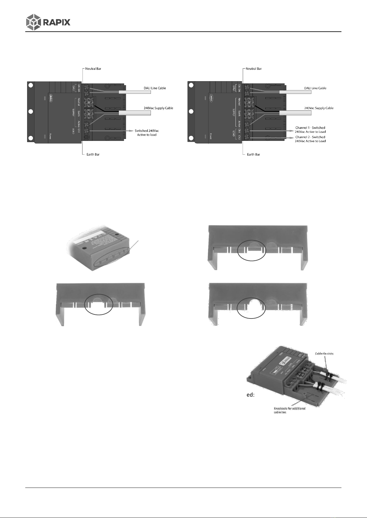
These Relays include a large area for terminating all 1.5 mm2or 2.5 mm2
double insulated cables: ac supply cables, switched load cables and DALI Line
cables.
To maximise contact life, these Relays include a proprietary zero cross turn
on feature. The load is switched on at the mains voltage zero-crossing point,
helping to reduce the effects of inrush current and maximise contact life.
Product Features
•General purpose load switching (ON and OFF) via received DALI commands.
•Capable of switching 16 AX at up to 220 - 240 V ac.
•Very high inrush current rating –500 A (2 ms).
•Includes large Neutral and Earth termination bars.
•Suitable for mounting in a ceiling void.
•Zero crossing detection to maximise relay contact life.
•Optional DIN rail mounting bracket.
•Fits through a 90 mm downlight hole.
•LED indicators (DALI and power).
•Uses a single DALI Short Address; can be including in up to 16 DALI Group Addresses and/or up to 16 DALI Scenes.
•DALI Short Address, Group Addresses and DALI Scenes are configured using RAPIX Addressing or RAPIX Integrator
software. Can also be commissioned using other DALI commissioning software that supports DALI Device Type 7.
•Complies with DALI standard IEC 62386 and Device Type 7 (Switching Function).
Important notes and safety information
WARNING –Electric shock may result in serious injury or death. Follow all warnings in this guide and on the
product. Work in accordance with the latest electrical safety practices.
•DALI system wiring is only single insulated from mains. Treat DALI wiring the same as mains wiring.
•There are no user serviceable parts inside the Relay. Do not attempt to disassemble or operate the device with any
covers removed.
•This Relay is intended for indoor use only.
Mounting
Surface Mounting
Three 6mm mounting holes are provided for mounting the device.
DIN Rail Mounting
For DIN rail mounting, use the optional DIN Rail mounting bracket (order code DGOZ-RLY-DINBKT)
Mount the optional mounting bracket onto
DIN rail. Lock into place by pushing up the
black locking pin at the bottom of the bracket
Locate the Relay device onto the two
pins at the bottom mounting bracket
Push the top of the Relay onto the
mounting bracket and clip into place
6mm Mounting holes

RAPIX DALI-2 Relay DGOZ-RLY-16A-01 / DGOZ-RLY-16A-02
Page 2 of 4
Wiring
To operate correctly, the DALI Relays must be connected to ac mains voltage and a DALI line, as shown below.
One Channel Relay
Two Channel Relay
Notes:
•The Relays are not ‘voltage-free’ type: The load (switched line) output has an internal high impedance connection to
Line input.
•The mains earth connection is optional and is not internally connected. Only the Mains Line & Neutral connections are
required. If a 3-core cable with Earth conductor is used, the included Earth bar can be used to loop the Earth wire.
•If required, the Neutral and Earth bars can be used to loop 3-core cables to the load or other parts of the circuit.
Cable entry tabs/knockouts for 1.5mm2, 2.5mm2 and 5-Core modular cables
The terminal cover includes cable entry tabs/knockouts for use with typical 1.5 mm2and 2.5 mm2Flat TPS/building cable.
Tab locations
Tab pushed backwards to accommodate 1.5mm2cable
Tab removed to accommodate 2.5mm2cable
Circular knockout removed to accommodate 5-core modular
wiring cable
Use cable ties to secure DALI mains supply and switched output cables
The base of the cable termination area has slots to tie down cables. Knockouts for
additional cable ties are also provided. Cable ties are included with the Relay.
Commissioning
To operate correctly, the DALI Relay must be programmed with the appropriate DALI
addresses. Depending on application, the following parameters may need to be configured:
•DALI Short Address;
•DALI Group Address(s);
•DALI Scene Address(s);
•Minimum Level and Maximum Level;
•Power On Level and System Failure Level;
•Fade Time and Fade Rate.
These parameters can be configured using RAPIX software, or any other DALI software which allows these standard DALI
parameters to be configured in a DALI Compliant Relay device.

RAPIX DALI-2 Relay DGOZ-RLY-16A-01 / DGOZ-RLY-16A-02
Page 3 of 4
Standards and compliance
The product is designed to meet/exceed the following Australian and International standards:
EMC and Electrical Safety Frameworks and Standards
IEC/EN 60669-2-1, AS/NZS 60669.2.1
IEC/EN 61000-3-2, -3, AS/NZS 61000-3-2, -3
IEC 61000-4-2, -3, -4, -5, -6, -8, -11, EN 61547:2009
AS/NZS CISPR 15:2011
IEC/EN 60669-2-1, AS/NZS 60669.2.1
DALI Standards and Compliance
IEC 62386-101
IEC 62386-102
IEC62386-208
EU Directives
2014/35/EU Low Voltage
2014/30/EU Electromagnetic Compatibility (EMC)
2015/863 Restriction of Hazardous Substances (RoHS) in Electrical and Electronic Equipment
Specifications
Number of Switched Outputs
DGOZ-RLY-16A-01: 1 DGOZ-RLY-16A-02: 2
Mains Supply Voltage
90 –250 V ac
Mains Frequency Range
47 –63 Hz
Electrical Isolation
4 kV (DALI to Mains)
Status Indicators
Power: Red ON DALI: Green ON
Load Rating
Resistive, Inductive, Fluorescent, LED, Capacitive: 10 A per channel
Motor: 2 A (1 HP) per channel
Inrush Current Rating
500 A (2 ms)
Relay Switch Operations
> 50 000 operations at rated load
Relay Contact Type
Bifurcated High Inrush
Zero Crossing Switching
At the zero-crossing of voltage for relay turn-on.
Standby Power
< 500 mW
DALI Line Current Draw
2 mA
DALI Device Type
Type 7
Connections
Screw terminal: up to 2 x 2.5 mm2per terminal or up to 3 x 1.5 mm2per terminal
Ambient operating temperature
0 - 50°C
Humidity
0% to 95% RH non-condensing
Ingress protection
IP20
Housing Material Type
Flame Retardant Polycarbonate, UL 94V-0
Weight
1 Channel: 155 g
2 Channel: 170 g
Mounting
Surface mount using 6 mm mounting holes, or using optional DIN rail bracket
Approvals
Indicators
DALI Green LED:
Indicator ON and fast-blink OFF once every 2 seconds
DALI OK
Indicator ON and multiple fast-blinks
DALI communications
Indicator OFF and fast-blink ON once every 2 seconds
Relay is functional, but no DALI Line voltage present
POWER Red LED:
Indicator ON
Mains power connected correctly
Indicator OFF
No mains connected

RAPIX DALI-2 Relay DGOZ-RLY-16A-01 / DGOZ-RLY-16A-02
Page 4 of 4
Dimensions
DALI Relay
Optional Mounting Bracket
Warranty
This product has a TWO YEAR warranty against manufacturing defects. The warranty applies from the date of purchase.
Refer to ozuno.com for the full conditions for warranty and returns process. A summary of the process:
1. Contact the seller of the goods, or in their absence contact Ozuno to request a return goods authorisation.
2. When a return is authorised, the goods must be returned to Ozuno at the owner’s expense for technical evaluation.
3. The warranty claim will be evaluated by Ozuno and accepted if the goods are found to be faulty, or rejected if the
fault was caused by conditions beyond the responsibility of Ozuno. Considerations of installation, removal, return,
freight and testing are not the responsibility of Ozuno.
The Australian Consumer Law requires the inclusion of the following statement with this Warranty:
Our goods come with guarantees that cannot be excluded under the Australian Consumer Law. You are entitled to a replacement
or refund for a major failure and for compensation for any other reasonably foreseeable loss or damage. You are also entitled to
have the goods repaired or replaced if the goods fail to be of acceptable quality and the failure does not amount to a major
failure.
L I G H T I N G
CONTROL SY STE M
Ozuno Trading Pty Ltd (Ozuno) reserves the right to alter the specifications, designs or other features of any items and to
discontinue any items at any time without notice and without liability. While every effort is made to ensure that all
information in this user and installation guide is correct, no warranty of accuracy is given and Ozuno shall not be liable for
any error.
Trademarks
RAPIX is a trademark of Ozuno Holdings Pty Ltd.
Identified trademarks and copyrights are the property of Ozuno Holdings Pty Ltd unless otherwise noted.
© Copyright
This guide is copyright to Ozuno Holdings Pty Ltd. Except as permitted under relevant law, no part of
this guide may be reproduced by any process without written permission and acknowledgement to
Ozuno Holdings Pty Ltd.
Sales: Ozuno Trading Pty Ltd, ABN 96 621 194 483
Contact
Technical Support: +61 (0) 400 021 462 (Australian Eastern Standard Time)
Or: support@ozuno.com
Version 1, April 2023 Item 14-22-001-001-01
This manual suits for next models
1
Table of contents