(Landline Phone Recommended)
Remote Programming
Keypad Programming
Step 1: Begin Program Mode
a. Press Enter
Step 2: Program Emergency Numbers
a. Press 1, Enter, (phone number), Stop.
To program numbers 2-5, repeat Step 2 a.
Example: To program emergency number 2, press
2, Enter, (phone number), Stop.
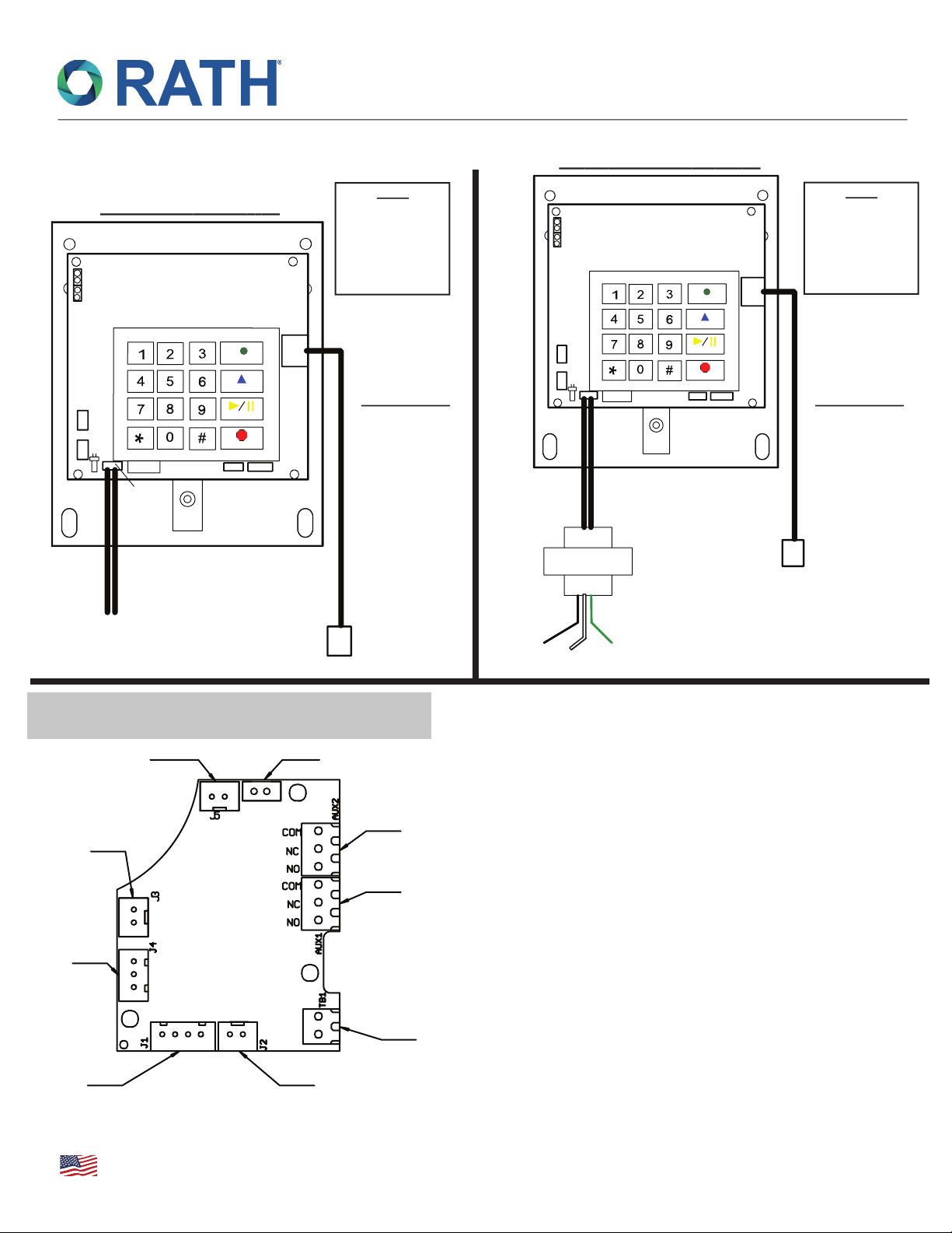
Note: If installed on a ring down line
(no dial tone) do not program phone number, press
the following: 1, 9, Enter, 2 (automatically sets the
timer for 3 minutes).
Step 3: Program Location Message
a. To turn on message press 1, 3, Enter, 2
b. Press 6, Record, wait for the “beep”, then speak
message, Stop. To replay message, press 6,
Play/Pause.
c. Program frequency of message, press
1, 3, Enter, __
0 = No message
2 = Plays message (2) times (default)
3 = Plays message until receiving party presses *
Note: Called party can replay message by pressing *,*.
Step 4: Exit Program Mode
a. Press Stop for 3 seconds
Step 1: Begin Program Mode
a. Call into phone
b. After first simulated ring, press #, #
c. Key in security code (default is 1111)
Step 2: Program Emergency Numbers
a. Press 1, *, (phone number), *, #.
To program numbers 2-5, repeat Step 2 a.
Example: To program emergency number 2, Press
2, *, (phone number), *, #. For a pause, press #, *.
Note: If installed on a ring down line (no dial tone) do
not program a phone number, press the following: 1, 9,
*, 2 (automatically sets the timer for 3 minutes).
Step 3: Program Location Message
a. To turn on message, press 1, 3, *, 2
b. Press 6, *, wait for the “beep”, then speak message,
#. To replay message, press 6, #.
c. Program frequency of message, press
1, 3, *, __
0 = No message
2 = Plays message (2) times (default)
3 = Plays message until receiving party presses *
Note: Called party can replay message by pressing *,*.
Step 4: Exit Program Mode
a. Press *, #, 0 (you will hear beep beep) *, #
Optional Programming Features
Program Talk Timer
(Default is 5 minutes, ring down is 3 minutes)
Keypad:
Press 8, Enter, (3 digit number in minutes)
Remote:
Press 8, *, (3 digit number in minutes)
Example: 2 minutes = 002
Note: After talk time expires, phone will prompt
called party to extend call for 3 minutes.
Phone Line Check: (Default is 10 minutes)
Keypad: Press 3, 4, Enter, (4 digit number
in HH:MM)
To turn off, press 23, Enter, 3, 23, Enter,
7284, 11, Enter, 2
Remote: Press 3, 4, *, (4 digit number in HH:MM)
To turn off, press 23, *, 3, 23, *, 7284, 11, *, 2
Example: 20 minutes = 0020, 10 hours = 1000
Example: 20 minutes = 0020, 10 hours = 1000
Step 1: Begin Program Mode
a. Press Enter
Step 2: Program ID Numbers for Phones 1-5
a. Press 7, Enter
b. Press *, 1-5 for corresponding elevator 1-5
Step 3: Program ID Numbers for Phones 6-10
a. Press 7, Enter
b. Press #, 1-5 for corresponding elevator 6-10
Step 4: Exit Program Mode
a. Press Stop for 3 seconds
Step 5: Confirm Consolidator Operation
a. Dial phone number connected to
SmartPhones: All phones will answer
b. To select individual phone:
Press *1 (Phone #1) Press #1 (Phone #6)
Press *2 (Phone #2) Press #2 (Phone #7)
Press *3 (Phone #3) Press #3 (Phone #8)
Press *4 (Phone #4) Press #4 (Phone #9)
Press *5 (Phone #5) Press #5 (Phone #10)
Press *0 (All Phones)
Consolidator Feature: (Allows up to (10) SmartPhones on a single
telephone line and toggle between them from an outside call)
RP8200910
Ver. 8
09/19
Detailed Programming Instructions (Standard Operations)
SmartPhone VI
N56W24720 N. Corporate Circle • Sussex, WI 53089
800-451-1460 • www.rathcommunications.com
MADE IN THE USA
3 YEAR WARRANTY