rauland TC4221 User manual

KI-1698B
TC4221 Digital Display
Installation
RAUUNDBORG
CORPORATIONl 3450 West Oakton Street, Skokie, Illinois 60076-2951 l (847) 679-0900
General Information
Description Parts Enclosed
This unit comes assembled on a
metal
baseplate. It con-
verts a standard push-button phone to a display phone that
can be used with Telecenter V, Telecenter IV, Telecenter
TCS, Telecenter System 21, or TCll00 systems. It has a
16-digit LCD readout and a “beeper” to annunciate call-ins.
The TC4221can be usedasadirect replacement for aTC4220,
but it offers a number of new features as well, notably its
capability of being individually addressedin a Telecenter V
and Telecenter System 21 system.
The following parts should come with the display:
4 1” x 21/2” double-sided foam strip, for fastening the
display to the telephone.
4 Nine-inch, six-conductor modular phone cord.
Number of Displays
The display matches the Rauland TC4204 Administrative
Telephone. It can be used with many other DTMF (dual-fre-
quency, multi-tone) desk phones, the only limitation being
aesthetics. Figure 1shows a typical placement.
Telecenter V and Telecenter System 21 systems have a
single display driver that can support up to 2,000 feet of
cabling and 16displays. Each display may beassignedits own
addresswith its DIP switch (see“Setting the DIP Switch,” the
final section of this manual).
Telecenter 1100, Telecenter IV, and Telecenter TCS sys-
tems cansupport up to 1,000feet of cabling and three displays
per display driver. Telecenter 1100systems have one display
driver, Telecenter IV systems have two display drivers, and
Telecenter TCS systems have six display drivers.
Figure 1. Typical Placement of Display
Related Manuals
Seethe appropriate system manuals for details on wiring
and programming:
Telecenter V
The main wiring diagram (KM1035) includes the wiring
for display phones. It is part of the Telecenter V drawings
manual, included in KI-1687.
Telecenter IV
The wiring diagram for display telephones (KM0684) is in
the Drawings and Glossarymanual (KI-1587), which ispart of
the main manuals (KI-1435). For programming information,
seeKI-1584, also part of the main manuals.
Telecenter TCS
The wiring diagram for display telephones (KM0837) is in
Diagnostics, Troubleshooting, and Drawings (KI-1550), which
91993
RAULAND-BORG CORPORATION.
Printed in U.S.A. Page 1 of 5
Orig. 2/92. Rev. 8/92, 9/93. 169802

TC4221 Digital Display
is part of the main manuals (KI-1579). For programming Telephone Interface Module installation manual (KI-1681).
information, seeKI-1538, also part of the main manuals. For programming information, see the 2524 programming
manual (KI-1629).
Telecenter 1100
The display module is recommended for Telecenter 1100 Telecenter System 21
systems, which include the CTLl Telephone Interface. See The wiring diagram for display phones (KM1121) is in the
drawings KM1032 and KM1033 in the CTLl ChronoCom Installation Drawings manual, KI-1767.
Installation
Right Way
Terminal side
Mechanical
Note: For Telecenter V and Telecenter System 21 systems,
set each display’s DIP switch before attaching the display to
a telephone. See“Setting the DIP Switch,” on the following
page.
Before attaching the assembly to the telephone, install the
nine-inch modular phone cord and anything elsethat might
be covered by the assembly. Use the double-sided foam to
secure the assembly to the phone. Do not cover anything
with the foam that you might need to remove in the future
(e.g.,the cord that runs from the display unit to the phone.
Caution: The foam bonds tightly to any hard surface it
touches. To assure a smooth installation, stick the foam to
the display unit first. Before touching the foam to the tele-
phone, make sure the display is properly aligned.
Wiring
This section tells the basic connections. For details, con-
sult the system manuals listed above and the manufacturer’s
manual for any other component (e.g., a special-features
telephone).
Observe Proper Polarity!
This is especially important for the display, which could
suffer damage from several minutes of exposure to reverse
polarity. To avoid damage, promptly disconnect the display
if it does not show the sign-on messagea few seconds after
you turn on the system. Check all wiring connections and
the polarity of the modular connectors on the desk cord and
the cord between the display and the phone.
The positive LCD output should beconnected to the “BK”
(“Black”) terminal, and the negative output to the “YL”
(“Yellow”) terminal of the telephone terminal block. See
Figure 2 and the wiring table.
Wrong Way
Terminal side Tab side
-d
Figure 2. Phone-Connector Polarity
Modular Cords
From a Modular Jack to the Display: For a standard
phone, useastandard four-conductor, six-position line cord.
Make sure that the modular plugs’ terminals are on the same
side of the cord (seeFigure 2).
From the Display Jack to the Telephone: Use the sup-
plied nine-inch
cord.
Connections
Use the following table or the wiring diagrams listed
earlier for the wiring connections.
Display and Telephone Connections I
Modular
Block
Terminal
Red
Green
Black (+)
Yellow (-)
Blue
White
Telephone R
T
TCIV/TCS
LLM
Terminals
R
T
LCD+
LCD-
(shield to Z)
see the
feature
phone’s
manual.
Page 2 9/93

TC4221 Digital Display
=-.
Note: (1) The display does
not
use the blue and white wires,
but simply passesthem on from its line receptacle to its
phone receptacle.
(2) Alternatively, you can wire Telecenter V display
phones to a punch block. Seethe main wiring diagram
(KM1035) in the TCV manuals. Telecenter System 21
displays can also be wired direct to the MSM port punch
blocks. See the appropriate diagram in the Telecenter
System 21 Installation Drawings manual, KI-1767.
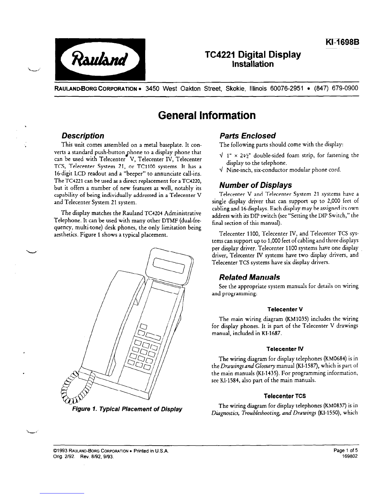
Adjusting the Display
The contrast adjustment for the display can be accessed
through the lower left hole in the back of the unit (asviewed
from the rear). Use a small, flat-blade screwdriver for the
adjustment.
Troubleshooting
Use a voltmeter to check the “Display” terminals (black
and yellow wires): during normal operation, you should get
a reading of 10 to 12 VDC. Within five seconds of being
turned on, the display should show an initial message,such
as “Vervvv DD,” where “VW” represents the software
version number, and “DD” represents the DIP-switch setting.
(Note that, the first time, you may needto adjust the contrast
to seethe message.)
Note: You can check the display apart from the system, by
using a separate power source (12 VDC, 5-10
mA).
Setting the DIPSwitch
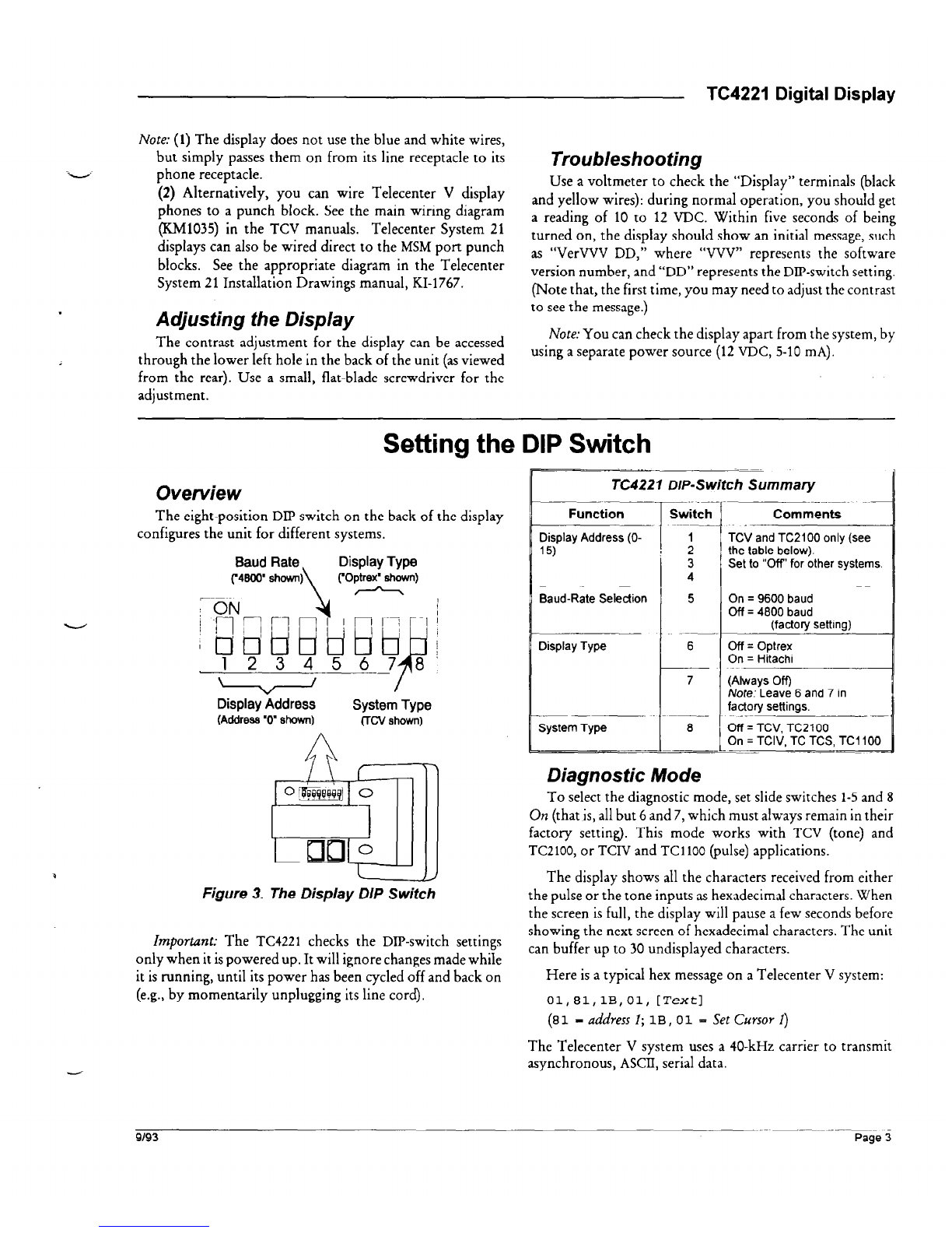
Overview
The eight-position DIP switch on the back of the display
configures the unit for different systems.
Baud Rate Display Type
("4800"’shown)
\ ("Optrex" shown)
, A
Display Address System Type
(Address ‘0” shown) (TCV shown)
Figure 3. The Display DIP Switch
Important: The
TC4221
checks the DIP-switch settings
only when it ispowered up. It will ignore changesmadewhile
it is running, until its power has been cycled off and back on
(e.g.,by momentarily unplugging its line cord).
TC4221 DIP-Switch Summary
Function
Display Address (0- 1
3
4
Baud-Rate Selection 5
Display Type 6
I
7
___.
System Type 8
.-
Comments
TCV and TC2100 only (see
the table below).
Set to “Off’ for other systems.
On = 9600 baud
Off = 4800 baud
(factory setting) -
Off = Optrex
On = Hitachi
(Always Off)
Note: Leave 6 and 7 in
factory settings.
Off = TCV, TC2100
On = TCIV, TC TCS, TC1100
Diagnostic Mode
To select the diagnostic mode, set slide switches 1-5and 8
On (that is, all but 6 and 7, which must always remain in their
factory setting). This mode works with TCV (tone) and
TC2100, or TCIV and TC1100 (pulse) applications.
The display shows all the characters received from either
the pulse or the tone inputs ashexadecimal characters. When
the screen is full, the display will pause afew seconds before
showing the next screen of hexadecimal characters. The unit
can buffer up to 30 undisplayed characters.
Here is a typical hex messageon a Telecenter V system:
01,81, 1B,01, [Text]
(81
- address 1;
1B , 01 =
SetCursor 1)
The Telecenter V system uses a 40-kHz carrier to transmit
asynchronous, ASCII, serial data.
9/93
Page 3

TC4221 Digital Display
Telecenter V & Telecenter System 21
For TCV or TC2100operation, push slide switch 8 Off and Becausethe Telecenter V and Telecenter System 21use a
single display drive, all displays receive the same messages,
5 on. However, only the unit with the corresponding addresswill
display an individual message.
Display Address
Setslide switches 1-4to give eachdisplay adifferent address
(the settings correspond to binary numbers, with the least-
significant-digit on the left):
Other Systems
For Telecenter IV, Telecenter TCS, and Telecenter 1100
operation, setslide switch 8 On and switches 1through 5 Off:
Slide-Switch Settings for Display Addresses
w=
Page4 9/93

Typical
wall-mounted
--
Schematic Detail
modular
receptacle Typical Display Conns:
B
(LCD+)
Y (LCD-)
Phone Line
T To any LLM line or
System
21 MSM port
R configured as phone
interface. See the
main TCIV, TCV, or
TCS manual for
configuration
requirements.
Also see the display-phone
wiring diagram for the TCIV
(KM0684), TCS (KM0837), or
TC2100 (KM1125) in
the
appropriate main manual.
TC4221 Digital Display
-s-----m
KM1040 H
(r&i$+j~~
SUYINK _ Printed on recycled paper using soy ink.

Table of contents
Other rauland Monitor manuals