Raven SCS 660 Manual

SCS 660
FOR GRANULAR APPLICATIONS
INSTALLATION
AND
SERVICE MANUAL


1
016-0159-572
9/97 TABLE OF CONTENTS
SYMBOL DEFINITION ............................................................................................................................................. 2
INTRODUCTION ...................................................................................................................................................... 3
INSTALLATION......................................................................................................................................................... 4
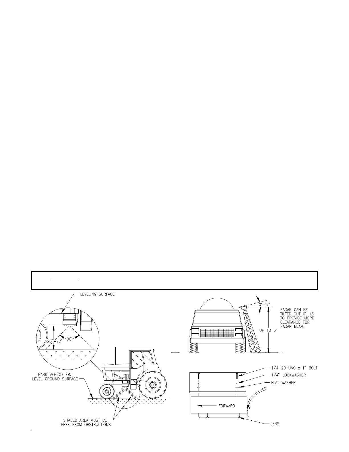
1. MOUNTING THE RAVEN RADAR SPEED SENSOR .................................... 4
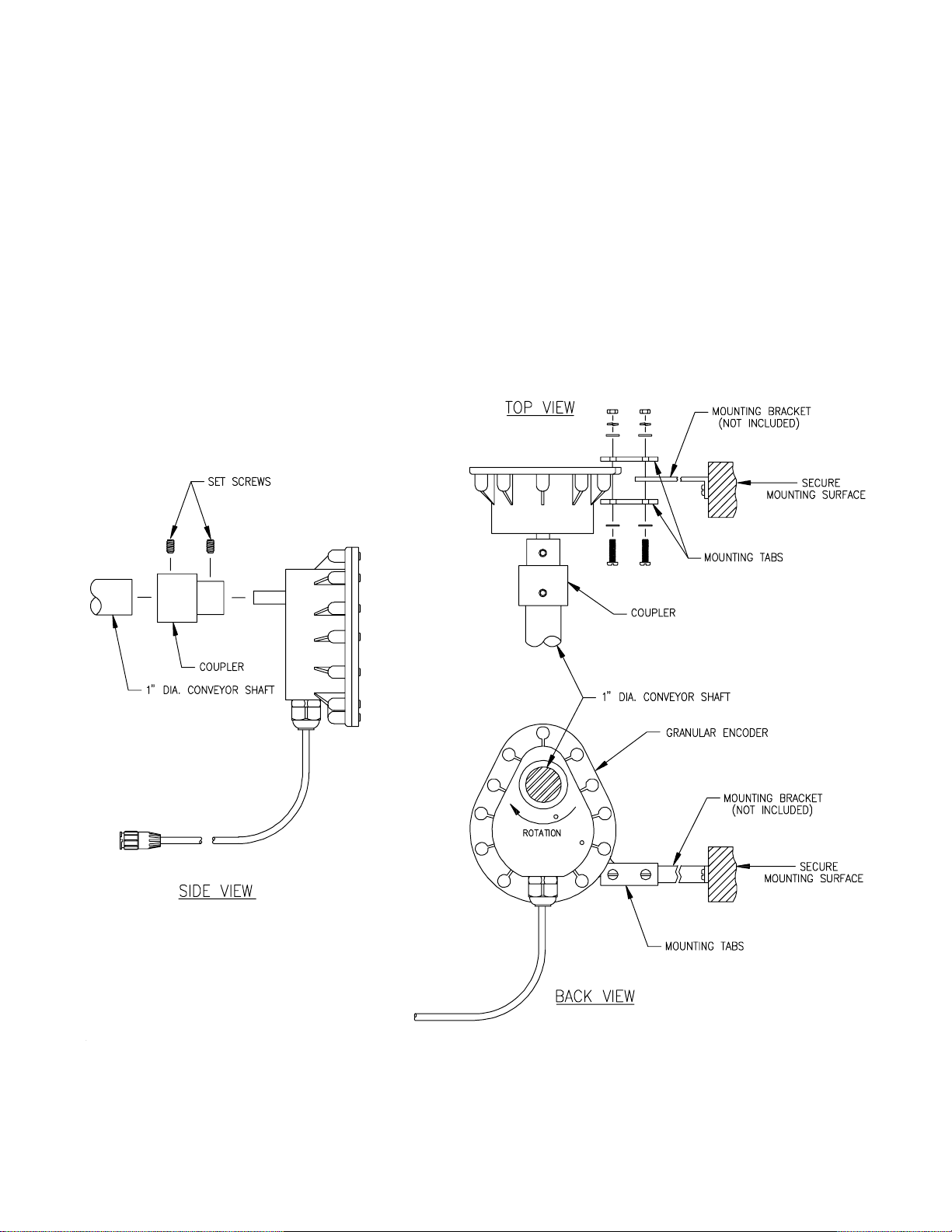
2. MOUNTING THE ENCODER ..................................................... 5
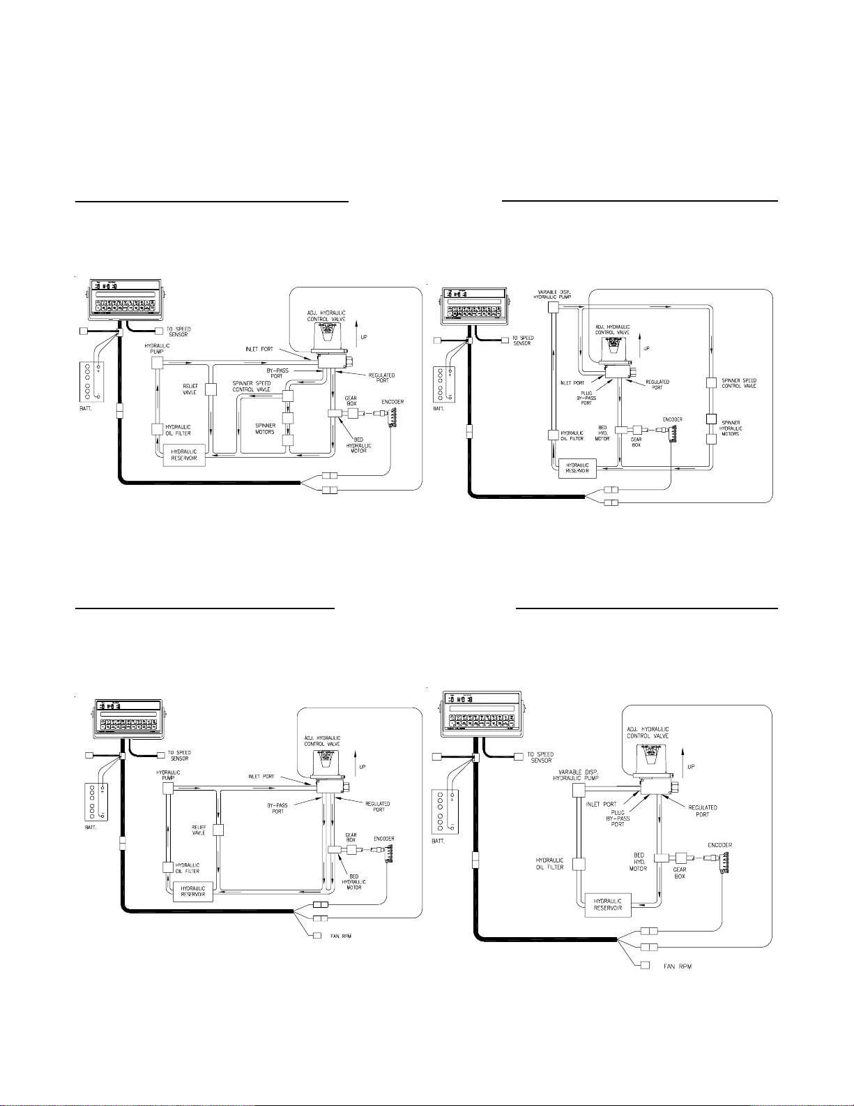
3. MOUNTING THE HYDRAULIC CONTROL VALVE ..................................... 6
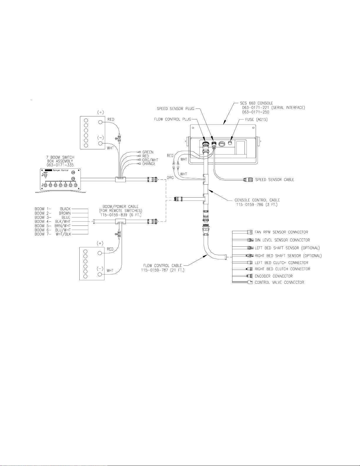
4. MOUNTING THE CONSOLE AND CABLING ......................................... 7
BATTERY CONNECTIONS...................................................................................................................................... 8
CONSOLE FEATURES ............................................................................................................................................ 9
CONSOLE CALIBRATION..................................................................................................................................... 10
1. CALCULATING "BOOM CAL" .................................................. 10
2. CALCULATING "SPEED CAL" ................................................. 10
3. CALCULATING "SPREADER CONSTANT" ......................................... 11
4. CALCULATING "METER CAL" ................................................. 11
5. CALCULATING "VALVE CAL" ................................................. 12
6. CALCULATING "RATE CAL" .................................................. 12
CONSOLE PROGRAMMING ................................................................................................................................. 13
1. INITIAL CONSOLE PROGRAMMING ............................................. 14
2. OTHER DISPLAY FEATURES .................................................. 19
3. SELF TEST FEATURE ....................................................... 20
4. VOLUME/MINUTE RATE FAULT ................................................ 20
5. VOLUME/AREA RATE ALARM .................................................. 20
6. LOW TANK FAULT ........................................................... 20
7. AUTOMATIC RATE +/- ...................................................... 21
8. CONTROL VALVE DELAY ..................................................... 21
9. SEQUENCE TO ACTIVATE DATA-LOCK .......................................... 21
10. SEQUENCE TO CHANGE DATA-LOCK ........................................... 21
11. ENTER MODE SEQUENCE WITH ACTIVATED DATA-LOCK .......................... 22
12. DATA MENU ............................................................... 22
13. DECIMAL SHIFT ........................................................... 29
INITIAL SYSTEM SET-UP...................................................................................................................................... 30
INITIAL SYSTEM FIELD TEST .............................................................................................................................. 30
TROUBLESHOOTING GUIDE............................................................................................................................... 31
APPENDIXES
1. PROCEDURE TO TEST SPEED SENSOR EXTENSION CABLES ............................................................... 33
2. PROCEDURE TO TEST ENCODER CABLES................................................................................................. 34
3. FAN RPM SENSOR INSTALLATION................................................................................................................ 35
4. BIN LEVEL SENSOR INSTALLATION.............................................................................................................. 36
5. SERIAL INTERFACE.......................................................................................................................................... 37
6. SCS 660 COMMUNICATION STRINGS........................................................................................................... 38
7. VERIFICATION OF SPREADER CONSTANT ................................................................................................. 39
8. WHEEL DRIVE SPEED SENSOR INSTALLATION ......................................................................................... 40
9. SPEEDOMETER DRIVE SPEED SENSOR INSTALLATION.......................................................................... 43
REPLACEMENT PARTS SHEETS

2
SYMBOL DEFINITION
DRY CONVERSIONS
Pound x 2.2 = Kilograms
Kilograms x .455 = Pounds
LENGTH
1 millimeter (mm) = 0.039 inch
1 centimeter (cm) = 0.393 inch
1 meter (m) = 3.281 feet
1 kilometer (km) = 0.621 mile
1 inch = 25.4 millimeters; 2.54 centimeters
1 mile = 1.609 kilometers
AREA
1 square meter = 10.764 square feet
1 hectare (ha) = 2.471 acres; 10,000 square meters
1 acre = 0.405 hectare; 43,560 square feet
1 square mile = 640 acres; 258.9 hectares
VOLUME
1 cubic meter = 1000 liters
1 cubic centimeter = 1 milliliter
PPM - Pounds per minute
kg/min - Kilograms per minute
PPA - Pounds per acre
kg/ha - Kilograms per hectare
PPK - Pounds per 1,000 sq. ft.
mm - Millimeters
cm - Centimeters
dm - Decimeters
m - Meter
MPH - Miles per hour
km - Kilometers
km/h - Kilometers per hour
US - Volume per acre
SI - Volume per hectare
TU - Volume per 1,000 sq. ft.
[] - Metric numbers
{} - 1,000 sq. ft. numbers

3
INTRODUCTION
The Raven SCS 660 (CONTROL SYSTEM) is designed to improve the uniformity of granular
applications. Its performance relies on installation and preventive maintenance of the
complete spreader. It is important that this Installation and Service Manual be reviewed
thoroughly before operating the system. This manual provides a simple step-by-step
procedure for installing and operating.
The SCS 660 consists of a Control Console, a Speed Sensor, an Encoder, and a Hydraulic
Control Valve. The Console mounts directly in the cab of the vehicle for easy operator
use. The Radar Speed Sensor is mounted to the frame of the spreader implement. (Other
Speed Sensors are also available). The Hydraulic Control Valve mounts to the framework
of the vehicle and the Encoder mounts to the conveyor drive shaft. Appropriate cabling
is furnished for field installation.
The operator sets the target weight per area to be applied and the SCS 660 automatically
maintains the application regardless of vehicle speed or gear selection. A manual
override switch allows the operator to manually control application for system check-
out and spot application. Actual weight per area being applied is displayed at all times.
The SCS 660 additionally functions as an area monitor, speed monitor, and volume
totalizer.
NOTE: The SCS 660 Control Console is designed to be used with external Boom
switches. In order for the Console to know when and which Boom is ON
or OFF, Boom signal wires are provided.

4
FIGURE 1
FIGURE 2
FIGURE 3
INSTALLATION
1. MOUNTING THE RAVEN RADAR SPEED SENSOR
See Appendix 8 for Wheel Drive Speed Sensor installation instructions.
See Appendix 9 for Speedometer Drive Speed Sensor installation instructions.
For mounting the Radar, the following guidelines will assure proper installation:
It is suggested that a large heavy mounting bracket, (P/N 107-0159-693) be attached
to the vehicle frame for mounting the Radar.
1) Park vehicle on level surface.
2) Select mounting site by considering the following:
a) The line of sight from the lens to the ground must not be obstructed by
structures or tires. Obstructions must not come closer than 20 inches to
the bottom of the Radar. See Figures 1 and 2.
b) The Radar lens must be parallel to the ground from front to back. Radar
can be tilted out 0-15 degrees to provide more clearance and miss
obstructions. See Figure 2.
c) The Radar should be mounted so that the length of the Radar is parallel with
direction of vehicle travel.
3) Use carpenters level to verify that mounting bracket is parallel to the ground.
4) Bolt mounting bracket to implement.
5) Bolt Radar to mounting bracket using mounting hardware. See Figure 3.
6) Connect Radar with Radar Interface Cable (P/N 115-0159-539) to the Console. The
Red wire should be connected to the Orange cable wire. The White wire should be
connected to the negative terminal of the battery. See Figure 10.
CAUTION: The connection of the Radar power in reverse polarity could result
in damage to the Radar.

5
2. MOUNTING THE ENCODER
1) Mount Encoder on output shaft of conveyor, or other shaft which rotates at a known
ratio to the conveyor. (See Figures 5,6,7,& 8).
2) Apply grease to Encoder shaft, conveyor shaft, and Encoder coupler (fits 1"
diameter conveyor shaft). Secure coupler to Encoder and conveyor shafts with set
screws provided.
3) Install mounting tabs to Encoder as shown in Figure 4. Connect mounting tab to
mounting bracket (not provided) to prevent Encoder from rotating. DO NOT rigidly
mount Encoder. Encoder is to be supported by coupler ONLY.
FIGURE 4

6
3. MOUNTING THE HYDRAULIC CONTROL VALVE
1) Refer to Figures 5,6,7,& 8 for typical placement of the Hydraulic Control Valve.
2) Valve is to be mounted with motor in the upright position.
PNEUMATIC SYSTEM
SPINNER SYSTEM
CLOSED HYDRAULIC SYSTEM (VARIABLE DISP. PUMP)
FIGURE 8FIGURE 7
FIGURE 6FIGURE 5
OPEN HYDRAULIC SYSTEM (FIXED DISP. PUMP) CLOSED HYDRAULIC SYSTEM (VARIABLE DISP. PUMP)
OPEN HYDRAULIC SYSTEM (FIXED DISP. PUMP)

7
4. MOUNTING THE CONSOLE AND CABLING
1) Mount the Console and Switch Box to a secure support inside the cab of the vehicle.
2) Connect the Console Control Cable to the plug in the back of the Console. (See
Figure 9). Route the Console Control Cable out of the vehicle cab and connect
with Flow Control Cable. (Extension cables are available from your Dealer).
FIGURE 9
3) Turn POWER ON/OFF switch OFF and route the Red and White battery wires to a 12-
volt battery. Attach the White battery wire to the NEGATIVE (-) terminal and the
Red battery wire directly to the POSITIVE (+) battery terminal. (See Figure 10).
(DO NOT CONNECT RED AND WHITE WIRES TO THE STARTER). Secure the battery wires
with plastic cable ties. DO NOT tie the battery wires close to the existing battery
leads or any other electrical wiring.
4) Connect the Flow Control Cable to the Encoder, Hydraulic Control Valve, and
sensors as required.
5) Connect the Speed Sensor to the plug in back of Console.
6) Secure Speed Sensor Cable and Console Control Cable with plastic cable ties.
7) Initial installation of the system is now complete.

8
BATTERY CONNECTIONS
FIGURE 10

9
POWER -Turns Console power ON or
OFF. Turning Console OFF does not
affect the data stored in the
computer.
CE -Exits ENTER mode and is also
used to select the features listed
in IMPORTANT box above.
Displays actual rate of application
and other messages.
ENTER -Used only to enter data into
the Console.
Displays function and calibration
data.
Manual override control provides
capability for spot applications.
Selects manual or fully automatic
control.
CONSOLE FEATURES
IMPORTANT:
This Console requires selection of US (acres), SI [hectares], or TU
{1,000 sq. ft.} area; SP1 (wheel drive, etc.) or SP2 (radar) speed sensor; LI
(liquid sprayer), GR1 (single bed belt), or GR2 (split bed belt); and C-Sd
(Standard Valve), C-F (Fast Valve), and C-FC (Fast Close Valve).
Console Revision can be determined by letter
stamped in REV box on label.
Console Program can be determined by letter
stamped in PGM box on label.
CALIBRATION KEYS -- Used to enter data into the
Console to calibrate the system.
BOOM CAL -- Width of Boom 1-2. Select
Boom number by using the
UP/DOWN arrow keys.
SPEED CAL -- Determined by Speed Sensor
METER CAL -- Density/Spreader Constant
VALVE CAL -- Valve Response Time
RATE 1 CAL -- Target Application Rate
RATE 2 CAL -- Target Application Rate
VOL/TANK -- Volume in Tank *
TIME -- Time/Date features
SELF TEST -- Simulates Vehicle Speed
*Volumes are displayed with both the RATE and
DATA displays when in GRANULAR mode.
063-0171-XXX
FUNCTION KEYS -- Used to Display Data
TOTAL AREA -- Total Area Applied
TOTAL VOLUME -- Total Volume Applied *
FIELD AREA -- Field Area Applied
FIELD VOLUME -- Field Volume *
DISTANCE -- Distance Traveled
SPEED -- Speed of Vehicle
VOL/MIN -- Volume Per Minute
AREA/HOUR -- Area per Hour
DATA MENU -- Various options

10
CONSOLE CALIBRATION
1. CALCULATING "BOOM CAL"
Enter the total width of the spread pattern in inches [cm] as boom length (See
"Definition of Boom Calibration keys").
2. CALCULATING "SPEED CAL"
Initial SPEED CAL is 598 [152]. Complete Steps 1 thru 6 to refine this number
after section "INITIAL CONSOLE PROGRAMMING" has been completed.
1) Set POWER switches to ON, all other switches to OFF.
2) Enter "0" in key labelled
3) Drive 1 mile [1 kilometer]. To achieve the most accurate calibration, accelerate
and decelerate slowly.
CAUTION: Do not use vehicle odometer to determine distance. Use section
lines or highway markers.
4) Read DISTANCE by depressing key labelled
DISTANCE should read a value of approximately 5280 [1000]. If it reads between
5260-5300 [990-1010], the SPEED CAL for the vehicle is 598 [152]. If the DISTANCE
display reads any other value, perform the following calculation:
EXAMPLE: Assume DISTANCE reads 5000 [980].
Corrected SPEED CAL = Old SPEED CAL x 5280
DISTANCE
ENGLISH UNITS: METRIC UNITS:
= 598 x 5280 = 631.48 = [152] x [1000] = [155]
5000 [980]
5) The number to enter for SPEED CAL is 631 [155].
6) Recheck the new SPEED CAL derived in Step 5 by repeating Steps 2 thru 5.

11
3. CALCULATING "SPREADER CONSTANT"
1) For RATE displayed in 1 lb [1 kg] increments:
L = Length in inches [centimeters], of belt travel per 1 revolution of Encoder
GH = Gate Height in inches [centimeters]
GW = Gate Width in inches [centimeters]
English (US) : Metric (SI):
Spreader Constant = 311,040 Spreader Constant = [18,000,000]
(1 lb) L x GH x GW (1 kg) [L] x [GH] x [GW]
EXAMPLE: 1) L = 13 inches [33 cm]
2) GH = 7 inches [18 cm]
3) GW = 15 inches [38 cm]
English (US):
Spreader Constant (1 lb) = 311,040
13 x 7 x 15
=311,140 = 228
1365
Metric (SI):
Spreader Constant (1 kg) = [18,000,000]
[33] x [18] x [38]
=[18,000,000] = [797]
[22,572]
NOTE: Verify Spreader Constant by performing Spreader Constant calibration
procedure in Appendix 7 before field application.
4. CALCULATING "METER CAL"
Product Density in lbs/cu.ft. [grams/liter] is entered as METER CAL.
NOTE: To increase the system accuracy when applying at low rates, use the
decimal shift feature as explained in CONSOLE PROGRAMMING.

12
5. CALCULATING "VALVE CAL"
1) The initial Control Valve calibration number is 2123 for C-Sd, or 743 for C-FC.
After operating the system, you may desire to refine this number. See definitions
below:
For FAST VALVE (C-F or C-FC):For STANDARD VALVE (C-Sd):
Valve Backlash Digit Controls the time of the first correction pulse after
a change in correction direction is detected.
(INC to DEC
-or-
DEC to INC).
Range: 1 to 9 1-Short Pulse
9-Long Pulse
Valve Speed Digit Controls response time of Control Valve motor.
CAUTION: Running the Control Valve too fast will
cause the system to oscillate.
C-Sd Valve Control Product 1 Range: 1 to 9 1-Slow
9-Fast
C-F or C-FC Valve Control Product 2-5 Ranges: 0 to 9 0-Fast
9-Slow
Brake Point Digit Sets the percent away from target rate at which the
Control Valve motor begins turning at a slower rate, so
as not to overshoot the desired rate.
Range: 0 to 9 0 = 5%
1 = 10%
9 = 90%
Dead-Band Digit Allowable difference between target and actual applica-
tion rate, where rate correction is not performed.
Range: 1 to 9 1 = 1%
9 = 9%
6. CALCULATING "RATE CAL"
The application rate in lbs/acre [kg/ha] is entered as RATE CAL. Consult the
equipment manual to insure that the selected gate opening is capable of applying
at this application rate.
NOTE: The Spreader Constant must be recalculated anytime the gate opening is
changed.

13
Depress the key in which
you wish to enter data.
Depress the ENTER key. An
"E" will illuminate in the
DATA display.
Depress the keys correspond-
ing to the number you wish to
enter (i.e. "5","7","2").
The numbers will be dis-
played as they are entered.
Complete the entry by again
depressing the ENTER key.
CONSOLE PROGRAMMING
When entering data into the Console, the entry sequence is always the same.
NOTE: DATA MUST BE ENTERED IN KEYS 3 THRU 8.

14
1. INITIAL CONSOLE PROGRAMMING
When you first turn on Console power, after all installation procedures have been
completed, the Console will flash "CAL" in the RATE display. This means you must
"calibrate", or program, the Console before it can be operated. This is a one-
time operation which does not have to be repeated. Turning OFF the POWER ON/OFF
switch does not affect the Console memory. All data is retained.
IMPORTANT:
If an entry selection error is made during Steps 1-8, place the
POWER ON/OFF switch to OFF. Depress and hold while placing
the POWER ON/OFF switch to ON. This will "reset" the Console.
The DATA display will show "US", and the RATE display will show "CAL". The
following steps must be followed:
1) Display US (acres), SI [hectares], or TU {1000 sq. ft.}.
a) Depressing momentarily steps the DATA display from US to SI.
b) Depressing momentarily steps the DATA display from SI to TU.
c) Depressing momentarily steps the DATA display from TU to US.
2) Selecting US, SI, or TU.
a) To select US, SI, or TU, step until the desired code is displayed
in DATA display.
b) Momentarily depress . The DATA display will now display SP1.
3) Display SP1 (wheel drives, etc.) or SP2 (radar sensor).
a) Depressing momentarily steps the DATA display from SP1 to SP2.
b) Depressing momentarily steps the DATA display from SP2 to SP1.
4) Selecting SP1 or SP2.
a) To select SP1 or SP2, step with until desired code is displayed in
DATA display.
b) Momentarily depress . The DATA display will now display LI.

15
5) Displaying LI (liquid sprayer), GR1 (single bed belt), or GR2 (split bed belt).
a) Depressing momentarily steps the DATA display from LI to GR1.
b) Depressing momentarily steps the DATA display from GR1 to GR2.
c) Depressing momentarily steps the DATA display from GR2 to LI.
6) Selecting LI, GR1, or GR2.
a) To select GR1, or GR2, step until desired code is displayed in the
DATA display.
NOTE: If a liquid application (LI) is desired, see the SCS 660 Liquid
Application Manual.
b) Momentarily depress . The data display will now display C-Sd.
7) Displaying C-Sd (Standard Valve), C-F (Fast Valve), or C-FC (Fast Close Valve).
a) Momentarily depressing steps the DATA display from C-Sd to C-F.
b) Momentarily depressing steps the DATA display from C-F to C-FC.
c) Momentarily depressing steps the DATA display from C-FC to C-Sd.
8) Selecting C-Sd, C-F, or C-FC.
a) To select C-Sd, C-F, or C-FC, step until desired code is displayed
in DATA display.
b) Momentarily depress . The DATA display will now display 0.

16
9) Definition of Boom Calibration keys.
Depressing this key displays selected boom number in DATA display.
EXAMPLE: Left Boom will be displayed as b-01, and Right Boom will be
displayed as b-02.
Depressing this key after selecting BOOM CAL changes the boom number.
EXAMPLE: b-01 will change to b-02.
Depressing this key after selecting BOOM CAL changes the boom number.
EXAMPLE: b-02 will change to b-01.
10) Enter Left Boom Width b-01.
a) Select boom b-01.
b) Use boom width as calculated under "CALCULATING BOOM CAL".
c) For single boom enter total boom width in inches.
For dual boom or split bed belt enter one half the total boom width
in inches.
11) Enter Right Boom Width b-02.
a) Select boom b-02.
b) Use boom width as calculated under "CALCULATING BOOM CAL".
c) For single boom enter 0.
For dual boom or split bed belt enter one half the total boom width
in inches.
12) Enter SPEED CAL as calculated under "CALCULATING SPEED CAL" in key labelled .
13) Enter METER CAL.
a) Depress and hold key for 5 seconds. When the DATA display flashes
0, enter the Spreader Constant as calculated under "CALCULATING SPREADER
CONSTANT".
b) Momentarily depress and enter Product Density.
NOTE: Verify Spreader Constant by performing Spreader Constant calibration
procedure in Appendix 7 before field application.
14) Enter VALVE CAL calibration number in key labelled .
Valve Calibration numbers: C-Sd (2123)
C-F (0743)
C-FC (0743)

17
15) Enter RATE 1 CAL (lbs/acre) [Kg/ha] target application rate in key labelled .
16) Enter RATE 2 CAL (lbs/acre) [Kg/ha] target application rate in key labelled
(If you do not use a second rate, enter the same rate as RATE 1 CAL).
YOU HAVE NOW COMPLETED PROGRAMMING THE CONSOLE
The flashing "CAL" will now extinguish. If not, repeat procedure starting at Step 9.
ENTERING ADDITIONAL DATA:
You may wish to enter data in the keys labelled and although it is not
required for the operation of the system.
1) ENTERING VOLUME:
Enter the estimated VOLUME in the TANK (lbs)[kg] in key labelled . Each
time the tank is refilled, this number must be re-entered.
IMPORTANT:
Both RATE and DATA displays windows are used to enter and view
volume totals. This enables a volume from 1 to 99,999,999 to be
entered into the Console. As information is entered, numbers move
from the DATA display window across to the RATE display window.
2) ENTERING TIME, DATE, AND POWER DOWN:
Definition of Time, Date, and Power Down Key:
Depressing this key displays selected Time features in DATA display.
EXAMPLE: RATE display will display "TInE" and DATA will display 0:00.
Depressing this key after selecting TIME toggles up through desired
features.
EXAMPLE: TIME, MONTH, DAY, YEAR, and POWER DOWN.
Depressing this key after selecting TIME toggles down through desired
features.
EXAMPLE: POWER DOWN, YEAR, DAY, MONTH and TIME.

18
1) Enter TIME
A) Select TIME
B) Enter TIME when RATE display shows "TInE".
2) Enter MONTH
A) Select MONTH
B) Enter MONTH when RATE display shows "OnTH".
3) Enter DAY
A) Select DAY
B) Enter DAY when RATE display shows "dAY"
4) Enter YEAR
A) Select YEAR
B) Enter YEAR when RATE display shows "YEAr"
5) POWER DOWN FEATURE
If the Console is not used for 10 days, it will go into a power down (low power)
mode of operation. In this mode, all data will be retained, but the time of day
clock will reset to 0:00. The delay time is initially set at 10 days, but can
be changed by the user.
A) Enter POWER DOWN
1) Select POWER DOWN
2) Enter POWER DOWN when RATE display shows "Pdn".
NOTE: This is a 24 hour clock. Therefore, all time after 12:59 p.m., add 12
hours. Thus, 8:30 a.m. is entered as 8:30, but 1:30 p.m. is entered as
13:30 in the keyboard.
Other manuals for SCS 660
1
Table of contents
Other Raven Music Mixer manuals