Raybar LINCE 150 User manual

RY-150LC
USER manual

PREFACE
Thank you for Choosing Raybar LINCE 150/RY-150LC motorcycle. We wish you a happy and reliable riding.
We are committed to customer satisfaction. We strive to provide great user experience by product innovation and excellent after
sales support.
This user manual is guide for you to understand function of various parts, riding operation, maintenance schedule and basic
maintenance of your new Raybar motorcycle. Please go through this manual to understand your motorcycle before using it.
Please contact your dealer for detailed information about the product and for after sale services.

CONTENTS
Motorcycle identification............................................................................................................................................................... 01
View and part names
Front top view...................................................................................................................................................................... 02
Right side view......................................................................................................................................................................03
Left side view........................................................................................................................................................................04
Parts function..................................................................................................................................................................................05
Inspection before riding.................................................................................................................................................................. 10
Starting engine & riding operation...................................................................................................................................................11
Maintenance schedule....................................................................................................................................................................12
General inspection & repair............................................................................................................................................................. 13
Technical specification.................................................................................................................................................................... 15
Electrical circuit diagram................................................................................................................................................................. 17

(1)
Note - Frame number and engine number is usually required for vehicle registration and insurance purpose.
Engine serial number is engraved on
crankcase assembly.
Vehicle identification number (VIN) is
stamped near main stand.
Frame number is engraved on main
tube of frame.
Engine Number VIN number Frame number
MOTORCYCLE IDENTIFICATION

FRONT TOP VIEW
(2)
1. Rear view Mirror
2. Left handle bar switches
3.
4. Right handle bar switches
5. Ignition switch
Speedometer
1
1
5
4
3
2

(3)
1. Rear grip
2. Tail lamp
3. Rear fender
4. Muffler
5. Rear tyre
6. Head lamp
7. Front fender
8. Front suspension
9. Front tyre
1
3
26
7
8
9
5
4
RIGHT SIDE VIEW

(4)
1. Indicator
2. Front disc brake
3. Front wheel
4. Seat
5. Rear wheel
6. Side stand
7. Main stand
4
5
6
7
1
2
3
LEFT SIDE VIEW

Meters and indicators
1. Odometer – Records accumulated riding distance.
2. Speedometer – Displays riding speed of motorcycle.
3. “ ” High beam indicator – Indicator turns ON when head lamp is in high beam.
4. Turn signal indicator left – Flashes when left turn signal switch is operated.
5. Turn signal indicator right – Flashes when right turn signal switch is operated.
6. Fuel Gauge – It indicates level of fuel contained in fuel tank.
7. Ignition switch –
(a) OFF position – All electrical circuits are cut off. The engine cannot be started. The key
can be removed in this position.
(b) ON position – The ignition circuit is completed. Engine can now be started. The key
cannot be removed in this position.
(c) LOCK position – To lock the steering, turn the handlebar all the way to the left. Push down the key and rotate to “LOCK”
position, let the key come up and now remove the key.
(5)
1
2
5
4
6
7
3
PARTS FUNCTION

Left handlebar control switches
1. Headlamp dimmer switch- This switch is used to change headlamp position from low
beam to high beam or vice versa.
2. Horn switch – Press the switch to operate the horn.
3. Turn signal switch – Operate the switch when turning right or left by pushing the switch
towards right or left.
(a) Turn right position – The right turning lamp and right turn signal Indicator on
instrument panel flashes.
(b) Turn left position–The left turning lamp & left turn signal indicator on instrument
panel flashes.
3
1
2
(6)

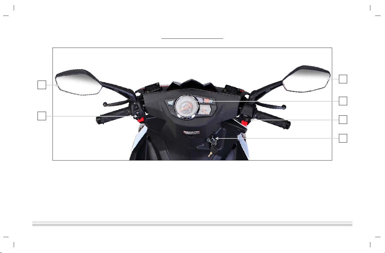
Right handlebar control switches
1. Headlamp switch –
(a) “ “ position – The headlamp , front parking light and tail lamp are turned ON.
(b) “ “ position – All lamps are turned OFF.
(c) “ “ position – Front parking lamp and tail lamp are turned ON.
2. Electric starter switch – When this switch is pressed, starter motor cranks the engine. This
switch should not be pressed over 5 seconds continuously.
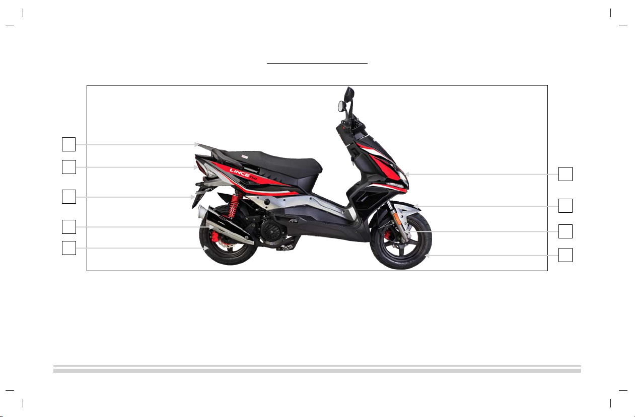
Seat
To open the seat insert the ignition key into seat lock and rotate. Then hold the seat and lift it up.
To lock the seat put it down and press downwards.
Fuel tank & Fuel tank cap
The capacity of the fuel tank is 5.5L.
(a) Position of the fuel tank – Fuel tank is mounted beneath the seat.
(b) Opening fuel tank cap –First you need to open the seat, then rotate the fuel tank cap
in anti-clockwise direction.
(c) Closing fuel tank cap - To close fuel tank cap, place the cap on fuel filling neck of fuel
tank and rotate it in clockwise direction.
1
2
(7)

Fuel filter
A fuel filter is a filter in the fuel line that screens out dirt and rust particles from the fuel.
From fuel tank, fuel goes to carburettor after passing through fuel filter.
Throttle
It controls the fuel air mixture flow from carburettor to engine. To increase the speed of the
vehicle, rotate throttle in backward direction and to decrease the speed of the vehicle, rotate
throttle in forward direction.
Tyre
Proper tyre pressure will provide maximum stability, mileage, riding comfort and tyre life.
Check tyre pressure frequently and adjust, if necessary. Select the right replacement tyres in
accordance with the tyre sizes given in table below -
(8)
Tyre Size Front 120/70-12
Tyre Size Rear 120/70-12

Starting lever or Kick
This is used to start the engine manually. To start the engine by kick, you need to place your
foot on the lever and push it downwards quickly.
Front brake lever
This is used to apply braking force on front wheels. When you want to stop the vehicle or
reduce speed, you need to pull front brake lever towards yourself. Always apply front and
rear brake together.
Rear brake lever
This is used to apply braking force on rear wheel. When you want to stop the vehicle or
reduce speed, you need to pull rear brake lever towards yourself. Always apply front and rear
brake together.
(9)

(10)
Inspection before riding
In order to ensure your safety, make a general inspection before riding according to the table given below –
No. Item Inspection Remark
1
2
3
4
5
6
7
8
9
10
11
12
13
14
For the vehicles with different riding miles
and performance, please adopt different
maintenance.
1. Elementary maintenance:
1000km~2000km riding, please lubricate
& check tyre pressure.
2. Secondary maintenance:
3000km~6000km riding, please check
wear and tear of parts and tighten
fasteners.
3. Advanced maintenance:
6000km~10000km riding, please
disassemble, inspect and do
troubleshooting.
4. Inspect and maintain your motorcycle
at professional maintenance station or
service centre.
Fuel system Check fuel capacity and fuel leakage
Carburetor Check carburettor for fuel leakage and idle speed for stability and proper
acceleration.
Lubrication oil Check luboil for quality and whether level is lower than the low scale mark.
Electrical system Check electrical system for proper functioning.
Battery Check battery for any leakage or spillage and acidic corrosion.
Front brake lever Check whether free stroke is appropriate
Rear brake lever Check whether free stroke is appropriate
Throttle lever Check throttle lever for flexibility and stroke of 2~6 mm.
Steering mechanism Check steering mechanism for flexibility and stability
Tyre/Wheel Check tyres for pressure and abrasion
Check Headlamp/Tail lamp/turning lamps for proper functioning.
Headlamp/Tail lamp/
Turning lamps
Brake Check brake disc/ brake pad/brake shoe for abrasion and proper functioning.
Main/Side stand Check whether main stand and side stand are bended or deformed and whether
they can return well.
Fasteners Check fasteners for looseness and possibility of falling.

accelerate
slow down
(11)
Starting Engine - Follow below mentioned steps to start the vehicle:
1. U nlock steering, and turn ignition key to “ON”position.
2. G rip front brake lever or rear brake lever.
3. Press kick downwards powerfully with foot or press electric starter switch with right
thumb.
4. Rotate throttle backwards to add proper volume of fuel to start motorcycle. Once
motorcycle has started, return kick lever. Preheat 3~5 minutes at idle speed
(1500±100)r/min.
Riding Operation –
1. A fter starting and preheating, return main and side stand.
2. Release the brake lever.
3. Rotate throttle slowly to accelerate.
Starting engine & riding operation

(12)
Maintenance schedule
Perform maintenance according to the odometer reading or time interval, whichever comes first.
NOTE : Inspect and clean, adjust, replace or lubricate as necessary,I=Inspect,C=Clean, R=Replace, T=Tighten.
TOOLS - To assist you in the performance of periodic maintenance, a tool kit is supplied.
Km Initial 1000 km Every 4000 km Every 8000 km
Miles 600 2400 4800
Months 5 20 40
I I -
T T -
I I -
I I -
I C R
I I -
R R -
I I -
C - C
Clean every 3,000km Replace every 12,000km
Valve clearance
Spark plug
Fuel hose Replace every four years
Engine oil and oil filter
Carburetor
Interval
Item
Fuel strainer cup
Battery ( Specific gravity of electrolyte )
Cylinder head nuts & exhaust pipe bolts
Camshaft drive chain
Air cleaner
I I -
I I -
I I -
- I I
I T -
Brake
Tyres
Steering
Front fork and rear suspension
Chassis bolts and nuts

(13)
Check and replacement of engine oil
Engine oil level check
(1) Stop the engine and park the motorcycle with main stand vertically in flat surface.
(2) Wait for one minute and then check the oil level through the engine oil level sight glass.
Replacement of engine oil
Following procedure needs to be followed to replace oil -
(1) Park the motorcycle vertically with main stand in flat surface.
(2) Remove the oil filler cap.
(3) Drain the oil by removing the drain plug located on the bottom of the engine.
(4) Once used oil is drained completely tighten the drain plug, fill engine with new engine
oil. Tighten the filler cap. Do not over tight the filler cap.
(5) Start engine in idle speed for 2~3 minutes.
(6) Stop the engine and wait for a minute. Inspect the engine oil level through the engine
oil level sight glass. Make sure that oil level is appropriate.
General inspection & repair
oil dipstick
top line bottom line

(14)
General inspection & repair
Spark plug
Check and replace
1. Disconnect the spark plug cap from the spark plug.
2. Clean any dirt from around the spark plug base. Remove the spark plug by using the plug wrench.
3. Inspect the electrodes for erosion or carbon deposit. If the erosion or deposit is heavy, replace
the plug. If there is small carbon deposit, clean carbon deposit with a plug cleaner or use a wire
brush.
4. Check the spark plug gap using a wire-type feeler gauge. The spark plug gap should be 0.6-0.7mm. If adjustment is required, bend the side
electrode carefully. Make sure the plug washer is in good condition.
5. With the plug washer attached, tighten the spark plug initially by hand to prevent cross threading and then tighten it by spark plug wrench.
6. Reconnect the spark plug cap.
Clean the air cleaner
At least once after every 4000Km, clean and immerse the air cleaner element into engine oil. If you drive your motorcycle in a dusty condition,
more frequent cleaning will be required.
Carburetor idle speed adjustment
Start up the engine and let the engine run until it warms up fully. After engine has warmed up, close the throttle and turn the idle speed adjuster
screw clockwise or anti-clockwise so that the engine may run at 1500r/min. The idle speed increases when the bolt is turned clockwise and the
idle speed decreases when the bolt is turned anti-clockwise. Idle speed of the carburetor should always be optimum. If the idle speed is not
appropriate, make sure to adjust the idle speed bolt once again.
0.6-0.7 mm

Air cooled
1
CB
Non balanced
150 CC
6. 7 kw/7500r/min
9.2N.m/6000r/min
57.4x57.8
9.5:1
Electric/ Kick start
95 KM/H
1.1L/100km
PD24J/18
Automatic
Telescopic
Spring coil type
Disc
Disc
(15)
Technical specification
Cooling
No. of cylinders
Type (CG or CB)
Balanced or Non balanced
Displacement/Capacity
Max. Power
Max. Torque
Bore x Stroke
Compression Ratio
Starting
Top speed
Mileage (Litres/100 kms)
Carburetor
Engine Specification
Clutch
Transmission & Chassis
Front
Rear
Suspension
Front Brake
Rear Brake
Brakes

3.5x12
3.5×12
120/70-12
120/70-12
Tubeless
MF-12V7AH
12V/35W
Normal
12V/3W
LED
Front 12V/1.8W, Rear 12V/2W
LED
A/C CDI
Mechanical
1825
675
1173
1293
147
5.5
117
(16)
Technical specification
Wheel Size Front
Wheel Size Rear
Tyre Size Front
Tyre Size Rear
Tyre Type (Tubeless or with Tube)
Battery
Head Lamp
Head Lamp Type (Normal/LED)
Tail/Stop Lamp
Tail Lamp Type (Normal/LED)
Turn Signal Lamp
Turn Signal Lamp Type (Normal/LED)
Ignition system
Speedometer
Length (mm)
Width (mm)
Height (mm)
Wheelbase (mm)
Ground Clearance (mm)
Fuel Tank Capacity (Litres)
Kerb Weight (kg)
Dimension
Electrical/Control System
Wheels & Tyres

www.raybarmotorcycles.com
/raybarmoto
This manual suits for next models
1
Table of contents
Other Raybar Motorcycle manuals