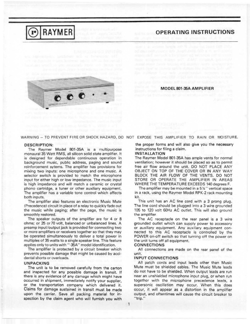
Raymer 801-35A User manual

©
RAYMER
OPERATING
INSTRUCTIONS
MODEL
801-35A
AMPLIFIER
WARNING
—
TO
PREVENT
FIRE
OR
SHOCK
HAZARD,
DO
NOT
EXPOSE
THIS
AMPLIFIER
TO
RAIN
OR
MOISTURE
DESCRIPTION:
The
Raymer
Model
801-35A
is
a
multipurpose
monaural
35
Watt
RMS,
all
silicon
solid
state
amplifier.
It
is
designed
for
dependable
continuous
operation
in
background
music,
public
address,
paging
and
sound
reinforcement
sytems.
The
amplifier
has
provisions
for
mixing
two
inputs:
one
microphone
and
one
music.
A
selector
switch
is
provided
to
match
the
microphone
input
for
either
high
or
low
impedance.
The
music
input
is
high
impedance
and
will
match
a
ceramic
or
crystal
phono
cartridge,
a
tuner
or
other
auxiliary
equipment.
The
amplifier
has
a
variable
tone
control
which
affects
both
inputs.
The
amplifier
also
features
an
electronic
Music
Mute
(Precedence)
circuit
in
place
of
a
relay
to
quickly
fade
out
the
music
while
paging;
after
the
page,
the
music
is
smoothly
restored.
The
speaker
outputs
of
the
amplifier
are
for
4
or
8
ohms;
or
25
or
70
volt,
balanced
or
unbalanced
lines.
A
preamp
input/output
jack
is
provided
for
connecting
two
or
more
amplifiers
or
receivers
together
so
that
they
may
be
operated
simultaneously
to
deliver
a
total
power
in
multiples
of
35
watts
to
a
single
speaker
line.
This
feature
applies
only
to
units
with
"-35A”
model
identification.
The
amplifier
is
protected
by
a
circuit
breaker
which
prevents
possible
damage
that
might
be
caused
by
acci¬
dental
shorts
or
overloads.
UNPACKING
The
unit
is
to
be
removed
carefully
from
the
carton
and
inspected
for
any
possible
damage
in
transit.
If
there
is
any
evidence
of
any
damage
which
might
have
occurred
in
shipment,
immediately
notify
your
supplier,
or
the
transportation
company
which
delivered
it.
Claims
for
damage
sustained
in
transit
must
be
made
upon
the
carrier.
Save
all
packing
material
for
in¬
spection
by
the
claim
agent
who
will
furnish
you
with
the
proper
forms
and
will
also
give
you
the
necessary
instructions
for
filing
a
claim.
INSTALLATION
The
Raymer
Model
801-35A
has
ample
vents
for
normal
ventilation;
however
it
should
be
placed
so
as
to
permit
free
air
flow
around
the
unit.
DO
NOT
PLACE
ANY
OBJECT
ON
TOP
OF
THE
COVER
OR
IN
ANY
WAY
BLOCK
THE
AIR
FLOW
OF
THE
VENTS.
DO
NOT
STORE
OR
OPERATE
THE
AMPLIFIER
IN
AREAS
WHERE
THE
TEMPERATURE
EXCEEDS
140
degrees
F.
The
amplifier
may
be
mounted
in
a
5%"
vertical
space
in
a
rack,
using
the
Raymer
Model
RPK-2
rack
mounting
kit.
This
unit
has
an
AC
line
cord
with
a
3
prong
plug.
The
line
cord
should
be
plugged
into
a
3
wire
grounded
105
to
120
volt
60Hz
AC
outlet.
This
will
also
ground
the
amplifier
The
AC
receptacle
on
the
rear
panel
is
a
3
wire
grounded
outlet
which
can
supply
power
to
accessory
or
auxiliary
equipment.
Any
auxiliary
equipment
con¬
nected
to
this
AC
receptacle
is
controlled
by
the
POWER
on-off
switch
so
that
turning
off
the
power
on
the
unit
turns
off
all
equipment.
CONNECTIONS
All
connections
are
made
on
the
rear
panel
of
the
unit.
INPUT
CONNECTIONS
All
patch
cords
and
input
leads
other
than
Music
Mute
must
be
shielded
cables.
The
Music
Mute
leads
do
not
have
to
be
shielded.
When
output
leads
are
run
near
an
unshielded
microphone
input
plug,
or
when
run
together
with
the
microphone
precedence
leads,
a
supersonic
oscillation
may
occur.
When
this
does
occur,
it
will
appear
as
a
distortion
in
the
amplifier
output,
and
oftentimes
will
cause
the
circuit
breaker
to
"trip."
1

INPUTS
The
Microphone
input
jacks
are
for
an
unbalanced
line
only.
If
it
is
necessary
to
use
a
balanced
input,
an
outboard
matching
transformer
such
as
Raymer
Model
LMT-150
must
be
used.
If
the
signal
source
is
a
tele¬
phone
line
or
a
500
ohm
input,
the
connection
can
be
made
to
the
amplifier
by
means
of
a
Raymer
Telephone
Matching
Adaptor
TM-2.
The
switch
alongside
each
microphone
input
selects
the
proper
input
impedance.
The
Hi-Z
position
will
match
either
crystal
or
high
impe¬
dance
dynamic
microphones;
the
Lo-Z
position
will
match
microphones
in
the
150
to
500
ohm
range.
If
it
is
desirable
to
fade
out
the
music
while
paging,
a
"dispatcher"
type
of
microphone
with
an
auxiliary
switch
having
a
pair
of
normally
open
contacts
should
be
used.
The
microphone
is
to
be
connected
as
shown
in
Figure
1.
FIGURE
U
TYPICAL
CONNECTION
FOR
A
SINGLE
MICROPHONE.
FOR
MORE
THAN
ONE
MIC
R0PH
ONE^CONNECTTHE
SWITCH
Cl
RCUITS
IN
PARALLEL.
CAUTION
To
avoid
possible
supersonic
oscillation
which
might
result
in
damage
to
the
unit,
it
is
mandatory
that
a
shielded
(metal
cover)
microphone
plug
be
used.
The
MUSIC
input
is
high
impedance
with
a
sensi¬
tivity
of
one-half
volt
and
will
accomodate
the
output
of
a
ceramic
phono
cartridge
or
the
output
from
any
pre¬
amplifier
such
as
tape,
phono,
etc.
If
the
source
into
the
MUSIC
input
is
from
leased
telephone
lines,
a
Raymer
TM-2
telephone
adaptor
is
required
to
match
the
telephone
lines
to
the
input.
The
music
channel
has
two
input
jacks
for
the
selection
of
a
desired
signal
source.
This
selection
is
controlled
by
a
slide
switch
directly
below
the
music
control.
The
Aux
input
is
high
impedance
and
is
identical
to
the
MUSIC
input.
The
Aux
input
may
be
used
in
place
of
the
MICROPHONE
3
input
by
means
of
a
selector
switch
located
directly
below
the
MIC
3/AUX
control.
OUTPUT
CONNECTIONS
The
speaker(s)
or
line
matching
transformers
are
connected
to
the
screw
terminal
board
located
on
the
rear
panel.
For
short
distances
any
ordinary
insulated
wire,
such
as
parallel
lamp
cord,
may
be
used.
Long
lines
have
an
appreciable
resistance
with
re¬
sultant
power
loss.
The
use
of
parallel
matching
trans¬
formers
on
either
25
volt
or
70
volt
lines
is
recom¬
mended
for
long
distances.
In
all
cases,
it
is
advisable
to
run
as
heavy
a
wire
as
possible
consistent
with
the
requirements.
To
avoid
inducing
hum
in
the
system,
do
not
parallel
speaker
cables
with
any
AC
line
power
cables.
70
volt
distribution
systems
often
require
the
speaker
lines
to
be
run
in
conduit.
To
determine
whether
they
should
be
run
in
conduit
check
with
local
city
codes
for
70
volt
system
requirements.
The
4
OHM
or
8
OHM
output
is
used
when
connec¬
ting
directly
to
the
speaker
voice
coils.
When
a
speaker
with
an
impedance
of
8
ohms
is
connected
to
the
amplifier,
use
the
terminals
on
the
amplifier
marked
GND
and
8
.
For
a
4
ohm
speaker
or
two
8
ohm
speakers
in
parallel,
use
GND
and
4
.
The
25
VOLT
or
70
VOLT
output
is
used
when
con¬
necting
to
speakers
which
have
line
matching
trans¬
formers.
Connecting
to
the
25
volt
or
70
volt
tap
on
the
unit
permits
the
use
of
a
number
of
speakers
each
with
its
own
corresponding
line
matching
transformer,
thereby
eliminating
the
necessity
of
calculating
im¬
pedances.
The
tap
on
the
line
matching
transformer
is
selected
to
give
the
power
desired
for
each
speaker.
The
total
of
all
the
power
settings
should
be
no
greater
than
the
amplifier
output
rating.
If
the
speaker
uses
a
25
or
70
volt
line
transformer,
connect
the
speaker
trans
former
to
the
terminals
marked
COM
and
25V
(or
70V)
according
to
the
line
desired.
For
an
unbalanced
line
connect
a
jumper
between
COM
and
GND;
if
a
bal¬
anced
output
line
is
used,
no
jumper
is
required.
Optimum
performance
of
any
transistor
amplifier
de¬
pends
on
the
proper
current
delivered
at
the
output
terminals.
Connecting
a
total
load
impedance
at
any
tap
less
than
the
impedance
indicated
on
the
back
panel
of
the
amplifier
will
cause
the
transistors
to
deliver
more
current
than
they
were
designed
for
and
will
deteriorate
the
performance
of
the
unit
and
cause
damage
to
the
transistors.
To
prevent
this
from
occurring
and
to
protect
the
components,
the
unit
is
equipped
with
a
circuit
breaker
that
will
trip
if
the
output
impedance
is
below
the
specified
rated
value;
for
example,
if
two
8
ohm
speakers
are
connected
in
parallel
(resulting
in
a
4
ohm
impedance),
and
in
turn
connected
to
the
8
ohm
output
terminal,
the
circuit
breaker
will
trip
as
soon
as
the
volume
control
is
turned
up
to
the
unit's
maximum
output.
The
circuit
breaker
located
on
the
rear
panel
protects
the
unit
from
drawing
excessive
AC
line
current
which
could
cause
damage
to
the
internal
components.
2

IN
THE
EVENT
THAT
THE
CIRCUIT
BREAKER
CONTINUES
TO
TRIP,
DO
NOT
ATTEMPT
TO
DE¬
FEAT
THE
FUNCTION
OF
THE
CIRCUIT
BREAKER.
HAVE
THE
TROUBLE
INVESTIGATED
BY
A
QUALI¬
FIED
SERVICE
TECHNICIAN
OR
RETURN
THE
UNIT
TO
THE
FACTORY.
PREAMP
INPUT/OUTPUT
The
preamp
in/out
jack
may
be
used
as
an
input
for
signaling,
or
as
an
output
for
an
external
amplifier,
or
as
an
interlock
for
parallel
amplifier
operation.
If
it
is
desirable
to
add
a
signaling
annunciator
or
alarm
to
the
music
and
page
system,
a
Raymer
Model
TGSP-3
Tone
Generator
may
be
connected
to
the
amplifier.
The
output
of
the
TGSP-3
should
be
connected
to
the
preamp
in/out
jack.
By
connecting
in
this
fashion
the
tone
or
alarm
is
unaffected
by
any
of
the
front
panel
controls.
Two
or
more
Raymer
35
watt
amplifiers
or
receivers
may
be
connected
in
parallel
to
deliver
a
total
output
in
multitudes
of
35
watts
to
one
single
speaker
line.
The
units
connected
together
for
parallel
operation
must
all
have
a
"-35A"
model
identification.
To
operate
these
units
into
a
single
speaker
line
requires
that
the
outputs
be
connected
either
in
series
or
in
parallel.
In
order
to
be
sure
that
each
of
these
units
is
driving
the
line
equally,
the
inputs
of
each
power
stage
must
be
connected
in
parallel.
To
do
this,
connect
the
preamp
in/out
jacks
of
the
units
together
by
means
of
a
jumper
cable
with
phono
plugs
at
each
end.
The
output
terminals
of
the
35
watt
units
have
been
phased
at
the
factory
so
that
each
terminal
is
in
phase
with
the
corresponding
terminal
of
any
other
35
watt
unit.
To
connect
the
outputs
in
series
or
parallel
the
terminals
should
be
wired
as
shown
in
Figure
2.
PARALLEL
CONNECTION
FIGURE
2;
OUTPUT
CONNECTIONS
FOR
PARALLEL
OR
SERIES
OPERATION.
WHEN
CONNECTING
THE
OUTPUTS
IN
SERIES,
MAKE
CERTAIN
THAT
THERE
IS
NO
JUMPER
CON¬
NECTION
BETWEEN
COM
AND
GND
ON
THE
SCREW
TERMINAL
BOARD.
WARRANTY
This
unit
has
been
very
carefully
inspected
and
is
warranted
to
be
free
from
defects
in
material
and
workman¬
ship
under
normal
use
and
service
for
a
period
of
one
year
from
date
of
sale
to
the
original
purchaser.
This
Warranty
does
not
extend
to
any
unit
which
has
been
subject
to
abuse,
misuse,
neglect,
accident,
improper
installation,
or
alterations.
The
obligation
of
Trutone
Electronics
under
this
Warranty
is
limited
to
the
repair
of
any
defect
in
ma¬
terial
or
workmanship
and/or
the
replacemnt
of
any
defective
part,
provided
the
unit
is
returned
to
Trutone
Elec*
tronics
Inc.
transportation
paid
within
the
year.
It
is
recommended
that
any
unit
on
which
service
is
required
be
processed
through
your
distributor
or
installation
company
wherever
possible.
This
Warranty
is
expressly
in
lieu
of
all
other
Warranties,
expressed
or
implied,
and
of
all
other
obligations
or
liabilities
on
our
part.
We
neither
assume
nor
authorize
any
other
person
to
assume
for
us
any
other
liability
in
con¬
nection'with
the
products
manufactured
by
Trutone
Electronics,
Inc.
Made
in
USA
by
TRUTONE
ELECTRONICS,
INC.
7315
Fulton
Avenue
•
North
Hollywood,
California
91605
•
(213)
875-0423
3

0T-I24
Other Raymer Amplifier manuals
Raymer
Raymer 1 Watt Amplifier 701 User manual
Raymer
Raymer Amplifier 810-100 User manual
Raymer
Raymer Amplifier 801-40 User manual
Raymer
Raymer Amplifier 800-40 User manual
Raymer
Raymer Amplifier 795-10 User manual
Raymer
Raymer Amplifier 800-35A User manual
Raymer
Raymer Amplifier 804-100A User manual

Raymer
Raymer 808-60 User manual
Raymer
Raymer Solid State Amplifier 790 User manual
Raymer
Raymer 1010 User manual
