manuals.online logo
Brands
  1. Home
  2. •
  3. Brands
  4. •
  5. Raymer
  6. •
  7. Amplifier
  8. •
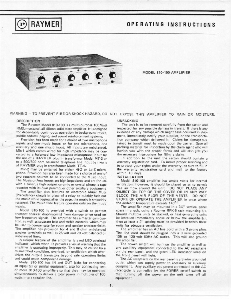
  9. Raymer 810-100 User manual

Raymer 810-100 User manual

RAYMER
OPERATING
INSTRUCTIONS
©
WARNING
-
TO
PREVENT
FIRE
OR
SHOCK
HAZARD,
DO
NOT
EXPOSE
THIS
AMPLIFIER
TO
RAIN
OR
MOISTURE
DESCRIPTION
UNPACKING
The
Raymer
Model
810-100
is
a
multi-purpose
100
Watt
RMS.
monaural,
all
silicon
solid
state
amplifier.
It
is
designed
for
dependable
continuous
operation
in
background
music,
public
address,
paging,
and
sound
reinforcement
systems.
Provision
has
been
made
for
a
choice
of
two
microphone
inputs
and
one
music
input;
or
for
one
microphone,
one
auxiliary
and
one
music
input.
All
inputs
are
unbalanced.
Mic-1
which
comes
wired
for
high
impedance
may
be
con¬
verted
to
a
balanced
low
impedance
microphone
input
by
the
use
of
a
RAYMER
plug
in
transformer
Model
MT-3
or
to
a
500/600
ohm
balanced
telephone
line
input
by
means
of
RAYMER
plug
in
transformer
Model
TT-4.
Mic-2
may
be
switched
for
either
Hi-Z
or
Lo-Z
micro¬
phone.
Provision
has
also
been
made
fora
choice
of
one
of
two
separate
sources
to
be
connected
to
the
Music
input.
The
Music
or
Aux
inputs
are
high
impedance
and
are
for
use
with
a
tuner,
a
high
output
ceramic
or
crystal
phono,
a
tape
recorder
with
its
own
preamp,
or
other
auxiliary
equipment
The
amplifier
also
features
an
electronic
Music
Mute
(Precedence)
circuit
in
place
of
a
relay
to
quickly
fade
out
the
music
while
paging;
after
the
page,
the
music
is
smoothly
restored.
The
music
fade
feature
operates
only
on
the
music
inputs.
Model
810-100
is
provided
with
a
switch
to
protect
trumpet
speaker
diaphragm(s)
from
damage
when
used
on
low
frequency
signals.
The
amplifier
has
a
master
gain
con¬
trol,
as
well
as
separate
bass
and
treble
controls,
which
may
be
used
to
compensate
for
room
and
speaker
characteristics.
The
amplifier
has
provision
for
4
and
8
ohm
unbalanced
speaker
terminals
as
well
as
25
volt
and
70
volt
balanced
or
unbalanced
lines.
A
unique
feature
of
the
amplifier
is
a
red
LED
overload
indicator,
which
when
lit
provides
a
visual
warning
that
the
amplifier
is
operating
improperly.
This
may
be
caused
by
a
mismatched
condition,
overload,
or
oscillation
which
over¬
drives
the
output
transistors
beyond
safe
operating
limits
and
could
cause
component
damage.
Model
810-100
has
IN
and
OUT
jacks
for
connecting
an
equalizer
or
similar
equipment,
also
for
connecting
two
or
more
810-100
amplifiers
so
that
they
may
be
operated
simultaneously
to
deliver
a
total
power
in
multiples
of
100
watts
into
a
speaker
line.
The
unit
is
to
be
removed
carefully
from
the
carton
and
inspected
for
any
possible
damage
in
transit.
If
there.is
any
evidence
of
any
damage
which
might
have
occurred
in
ship¬
ment,
immediately
notify
your
supplier,
or
the
transporta¬
tion
company
which
delivered
it.
Claims
for
damage
sus¬
tained
in
transit
must
be
made
upon
the
carrier.
Save
all
packing
material
for
inspection
by
the
claim
agent
who
will
furnish
you
with
the
proper
forms
and
will
also
give
you
the
necessary
instructions
for
filing
a
claim.
In
addition
to
the
unit
the
carton
should
contain
a
warranty
registration
card.
To
insure
proper
servicing
and
to
protect
your
rights
under
the
warranty,
be
sure
to
fill
in
the
warranty
registration
card
and
mail
to
the
factory
within
10
days.
INSTALLATION
Model
810-100
amplifier
has
ample
vents
for
normal
ventilation;
however,
it
should
be
placed
so
as
to
permit
free
air
flow
around
the
unit.
DO
NOT
PLACE
ANY
OBJECT
ON
TOP
OF
THE
COVER
OR
IN
ANY
WAY
BLOCK
THE
AIR
FLOW
OF
THE
VENTS.
DO
NOT
STORE
OR
OPERATE
THE
AMPLIFIER
in
areas
where
the
ambient
temperature
exceeds
140°F.
The
amplifier
may
be
mounted
in
a
3%"
vertical
panel
space
in
a
rack,
using
a
Raymer
RPK-5
rack
mounting
kit.
Should
multiple
units
be
stacked,
or
heat
generating
units
be
installed
immediately
above
or
below
the
amplifier(s),
then
at
least
a
2"
spacing
must
be
provided
between
these
units
for
adequate
ventilation.
The
amplifier
has
an
AC
line
cord
with
a
3
prong
plug.
The
line
cord
should
be
plugged
into
a
3
wire
grounded
105
to
120
volt
60Hz
AC
outlet.
This
will
also
ground
the
amplifier.
The
power
switch
will
turn
on
the
amplifier
as
well
as
any
auxiliary
equipment
connected
to
the
AC
receptacle
on
the
rear
panel,
and
the
green
LED
indicator
lamp
on
the
front
panel
will
light.
The
AC
receptacle
on
the
rear
panel
is
a
3
wire
grounded
outlet
which
can
supply
power
to
accessory
or
auxiliary
equipment.
Any
auxiliary
equipment
connected
to
this
AC
receptacle
is
controlled
by
the
POWER
on-off
switch
so
that
turning
off
the
power
on
the
unit
turns
off
all
equipment.
-
1
-
.
r
Figure
1.
Rear
Panel
of
Amplifier
CONNECTIONS
All
connections
are
made
on
the
rear
panel
as
shown
in
Figure
1.
THE
REMOVAL
OF
THE
COVER
AND
JUMPER
WIRES
FOR
THE
INSERTION
OF
EITHER
TRANS¬
FORMER
MUST
BE
DONE
BY
A
QUALIFIED
TECHNI¬
CIAN.
BE
SURE
THE
POWER
CORD
IS
DISCON¬
NECTED
BEFORE
REMOVING
THE
COVER.
INPUT
CONNECTIONS
AND
CONTROLS
All
patch
cords
and
input
leads
other
than
Music
Mute
must
be
shielded
cables.
The
Music
Mute
leads
do
not
have
to
be
shielded.
When
output
leads
are
run
near
an
unshielded
microphone
input
plug,
or
when
run
together
with
the
microphone
precedence
leads,
a
supersonic
oscilla¬
tion
may
occur.
When
this
does
occur,
it
will
appear
as
a
distortion
in
the
amplifier
output,
and
oftentimes
will
cause
the
circuit
breaker
to
“trip".
To
prevent
this
oscillation
from
occurring,
it
is
recom¬
mended
that
shielded
microphone
plugs
be
used
wherever
possible.
In
the
event
that
an
unshielded
plug
or
a
molded
cable
assembly
is
used,
keep
the
output
leads
away
from
the
Microphone
input(s)
and
Microphone
precedence
leads.
In
order
to
make
the
connection
to
MIC-1
use
a
Cannon
XLR-311C
or
equivalent
connector
wired
as
shown
in
Figure
2.
FIGURE
2.‘
MICROPHONE
1
INPUT
CONNECTIONS.
MIC-1
is
wired
for
an
unbalanced
high
impedance
micro¬
phone.
For
a
low
impedance
balanced
microphone
input
remove
the
cover
of
the
amplifier
as
well
as
the
jumpers
in
the
socket
inside
the
amplifier,
and
insert
a
Raymer
Model
MT-3
microphone
transformer
in
the
socket.
When
the
paging
source
is
from
telephone
lines,
the
Raymer
Model
TT-4
telephone
input
transformer
is
to
be
inserted
in
the
socket.
Typical
input
wiring
from
telephone
lines
is
shown
in
Figure
3.
The
two
pair
of
lines
furnished
by
the
telephone
company
are
identified
as
RING
AND
TIP
(voice
transmission
pair)
and
CONTACT
CLOSURE
(normally
open
relay
contacts).
When
it
is
not
necessary
to
mute
the
music
during
page
or
the
music
channel
of
the
amplifier
is
not
used,
the
CONTACT
CLOSURE
pair
is
not
required.
Interconnection
to
a
private
telephone
system
is
shown
in
Figure
4.
FIGURE4'.
PRIVATE
a
HONE
SYSTEM
,NPUT
CONNECTIONS
WHEN
USING
TT-4
input
TRANSFORMER.
The
slide
switch
directly
below
the
MIC-2/AUX
on
the
front
panel
will
permit
the
use
of
either
a
microphone
(Hi-Z
or
Lo-Z)
or
any
auxiliary
high
impedance
input.
When
this
switch
is
in
the
AUX
position
the
auxiliary
source
is
not
controlled
by
the
electronic
fading
(muting)
circuit.
The
microphone
input
jack
is
for
unbalanced
lines
only.
If
it
is
necessary
to
use
a
balanced
microphone
input,
use
Raymer
Model
LMT-150
microphone
matching
trans¬
former.
The
switch
alongside
the
MIC-2
input
jack
selects
the
proper
input
impedance.
The
Hi-Z
position
will
match
either
crystal
or
high
impedance
dynamic
microphones;
the
Lo-Z
position
will
match
microphones
in
the
150
to
500
ohm
range.
The
music
channel
has
two
input
jacks
(MUSIC
1-2)
for
selection
of
the
desired
signal
source.
This
selection
is
con¬
trolled
by
a
slide
switch
directly
below
the
MUSIC
control
and
is
marked
"1-2"
on
the
front
panel.
Either
input
is
for
a
high
impedance
source
such
as
a
tuner,
a
high
output
ceramic
or
crystal
phono,
a
tape
recorder
with
its
own
preamp,
or
other
auxiliary
equipment
of
a
similar
nature.
If
the
signal
source
is
a
telephone
line
or
a
500
ohm
input,
the
connection
can
be
made
to
the
amplifier
by
means
of
a
Raymer
Telephone
Matching
Adaptor
Model
TM-2.
If
it
is
desirable
to
fade
out
the
music
while
paging,
a
"dispatcher"
type
of
microphone
with
an
auxiliary
switch
having
a
pair
of
normally
open
contacts
should
be
used.
The
microphone
is
to
be
connected
as
shown
in
Figure
5.
FIGURE
SI
TELEPHONE
INPUT
CONNECTIONS
WHEN
USINC
TT-4
INPUT
TRANSFORMER.
FIGURE5:
VC-2
CONNECT
ON
*0RA
SINGLE
MICRCPHO>IE.FOR
MORE
THAN
ONE
MICK=H0N£,CONNECTCCIITROLCiaC
JITS
IN
PARALLEL.
A
J
Individual
volume
controls
are
used
to
adjust
the
level
of
the
MIC,
MUSIC,
or
AUX
input
channels.
The
MASTER
control
will
regulate
the
gain
of
all
inputs
simultaneously.
The
BASS
and
TREBLE
controls
should
be
set
to
com¬
pensate
for
room
and
speaker
characteristics
or
for
undesir¬
able
effects
of
acoustic
feedback.
When
both
controls
are
in
the
center
position
they
will
provide
a
flat
response.
Turning
the
Bass
control
to
the
left
reduces
the
bass
response.
Turning
the
Treble
control
to
the
left
reduces
the
high
frequency
response
of
the
amplifier.
Where
a
system
either
has
acoustic
feedback
or
is
on
the
verge
of
feedback,
the
undesirable
effects
may
sometimes
be
reduced
by
adjustments
of
both
the
Bass
and
Treble
controls.
In
order
to
protect
horn
loaded
drivers,
the
TRUMPET
PROTECT
switch
on
the
rear
panel
should
be
placed
in
the
"Trumpet
Protect"
position.
This
reduces
the
bass
frequen¬
cies
and
protects
the
driver
diaphragms
from
possible
damage.
For
use
with
cone
type
loud
speakers,
the
switch
should
be
placed
in
the
"Normal"
position.
The
output
terminals
of
the
810-100
have
been
phased
at
the
factory
so
that
each
termTnal
is
in
phase
with
the
corresponding
terminal
of
any
other
Raymer
810-100
amplifier.
For
connecting
the
amplifier
in
either
parallel
or
series,
the
terminals
should
be
wired
as
shown
in
Figure
7.
FIGURE
7:0UTPUT
CONNECTIONS
EQR
SERIES
OR
PARALLEL
OPERATION.
PREAMP
OUTPUT,
AMPLIFIER
INPUT
-
These
jacks
may
be
used
for
either
input
or
output
applications.
They
are
connected
electrically
between
the
preamplifier
and
power
amplifier
sections
of
Model
810-100,
and
may
therefore
be
used
(1)
as
the
output
of
the
preamplifiers
into
an
external
amplifier
and/or
tape
recorder,
or
(2)
from
the
output
of
an
external
source
into
the
power
amplifier
sec¬
tion.
When
the
Preamp
Output
jack
is
used
to
feed
an
external
amplifier
or
tape
recorder,
the
bridging
circuit
is
affected
by
the
Master
Volume,
Bass,
and
Treble
controls.
When
the
Amplifier
Input
jack
is
used
as
the
input
from
an
external
source
(such
as
a
microphone
mixer-preamplifier
when
additional
microphones
are
required)
the
reproduc¬
tion
from
the
external
source
will
not
be
affected
by
the
Bass
and
Treble
controls.
By
interconnecting
or
bridging
the
PREAMP
OUTPUT
or
the
AMPLIFIER
INPUT
jack
of
two
or
more
Raymer
810-100
amplifiers
with
a
patchcord,
they
may
be
operated
simultaneously
to
deliver
a
total
output
in
multi¬
ples
of
100
watts
into
one
speaker
line,
or
separate
speaker
lines
if
desired.
See
Figure
6.
In
the
event
it
is
desired
to
connect
an
equalizer
or
similar
equipment
to
a
single
810-100
amplifier,
the
PRE¬
AMP
OUTPUT
and
AMPLIFIER
INPUT
jacks
are
to
be
used.
In
order
to
use
the
additional
equipment,
it
will
be
necessary
to
remove
the
jumper
wire
between
the
jacks
which
is
located
internally.
When
this
external
equipment
is
to
be
used
with
amplifiers
paralleled
for
increased
power
to
the
speaker
lines,
the
interior
jumper
wire
shorting
the
jacks
in
each
amplifier
must
be
removed.
The
PREAMP
OUTPUT
jacks
of
all
the
amplifiers
are
connected
together
with
a
patchcord
and
the
AMPLIFIER
INPUT
jacks
are
also
connected
together
in
a
similar
manner
as
shown
in
Figure
8.
Note
—
All
internal
jumper
wires
must
be
removed
by
a
qualified
service
technician.
'NPUT
>
PREAMP
_
'_
PRFAM
ACCESSORY
1EQUIPMENT
I
PREAMP
OUTPUT
AMPLIFIER
INPUT
PREAMP
OUTPUT
REQUIRED
FOR
opewItion
amplifier
UHtKAIIUN
1NPUT
uuirgi
_
_
i
v
ru
i_
.
__
IINPU
•0
C
D—<v“0
.•«>-£>-
Cp@
HGURE
8:OPERATION
WITH
ACCESSORY
EQUIPMENT
RtQUIRES
REMOVAL
OF
INTERNAL
JUMPER
IN
AMPLIFIER.
FlGUREo'.ElTHER
JACK
MAY
tE
USED
TO
PARALLEL
8I0-'0L
AMPL
!
F
lERS,
ONLY
IF
IN~ERNAL
JUMPER
HAS
NOT
BEEN
REMOVED.
CAUTION:
BEFORE
OPERATING
AMPLIFIERS
CON¬
NECTED
EITHER
IN
SERIES
OR
PARALLEL,
MAKE
CERTAIN
THAT
THE
TRUMPET
PROTECT
SWITCHES
ARE
IN
THE
SAME
POSITION
ON
ALL
AMPLIFIERS.
WHEN
CONNECTING
THE
OUTPUTS
IN
SERIES,
MAKE
CERTAIN
THAT
THERE
IS
NO
JUMPER
CONNECTION
BETWEEN
COM
AND
GND
ON
THE
SCREW
TERMINAL
BOARD.
The
red
LED
"Overload"
indicator
on
the
front
panel
monitors
the
output
transistors
and
when
it
is
illuminated
continuously
it
is
a
warning
that
the
amplifier
is
being
operated
improperly.
This
condition
could
be
caused
by
mismatch
of
output
load,
incorrect
output
impedance,
short
circuit
in
the
output,
or
that
the
amplifier
is
oscillating
(which
could
be
caused
by
improper
shielding
or
position
of
input
leads)
and
may
result
in
the
circuit
breaker
tripping.
To
correct
and
localize
the
problem,
first
turn
each
input
control
to
"0".
If
the
LED
is
still
illuminated,
then
reduce
the
Master
control
to
"0".
If
the
LED
light
goes
out,
then
the
trouble
is
more
than
likely
in
the
external
equipment
plugged
into
the
PREAMP
OUTPUT/AMPLIFIER
INPUT
jacks.
If
the
light
does
not
go
out,
have
the
amplifier
serviced
by
a
qualified
service
technician
or
return
the
unit
to
the
factory.
Occasional
flickering
of
the
LED
means
that
the
ampli¬
fier
is
being
driven
to
the
maximum
on
peaks
of
the
pro¬
gram
material,
which
is
not
harmful
nor
will
in
any
way
damage
the
amplifier.
-
3
-
OUTPUT
CONNECTIONS
The
speaker(s)
or
line
matching
transformers
are
con¬
nected
to
the
screw
terminal
board
located
on
the
rear
panel.
For
short
distances
any
ordinary
insulated
wire,
such
as
parallel
lamp
cord,
may
be
used.
Long
lines
have
an
appreciable
resistance
with
resultant
power
loss.
The
use
of
parallel
matching
transformers
on
either
25
volt
or
70
volt
lines
is
recommended
for
long
distances.
In
all
cases,
it
is
advisable
to
run
as
heavy
a
wire
as
possible
consistent
with
the
requirements.
To
avoid
inducing
hum
in
the
system,
do
not
parallel
speaker
cables
with
any
AC
line
power
cables.
70
volt
distribution
systems
often
require
the
speaker
lines
to
be
run
in
conduit.
To
determine
whether
they
should
be
run
in
conduit
check
with
local
city
codes
for
70
volt
system
requirements.
The
4
OHM
or
8
OHM
output
is
used
when
con¬
necting
directly
to
the
speaker
voice
coils.
When
a
speaker
with
an
impedance
of
8
ohms
is
connected
to
the
amplifier,
use
the
terminals
on
the
amplifier
marked
GND
and
8S2.
For
a
4
ohm
speaker
or
two
8
ohm
speakers
in
parallel,
use
GND
and
4f2.
The
25
VOLT
or
70
VOLT
output
is
used
when
con¬
necting
to
speakers
which
have
line
matching
transformers.
Connecting
to
the
25
volt
or
70
volt
tap
on
the
unit
permits
the
use
of
a
number
of
speakers
each
with
its
own
corre¬
sponding
line
matching
transformer,
thereby
eliminating
the
necessity
of
calculating
impedances.
The
tap
on
the
line
matching
transformer
is
selected
to
give
the
power
desired
for
each
speaker.
The
total
of
all
the
power
settings
should
be
no
greater
than
the
amplifier
output
rating.
If
the
speaker
uses
a
25
or
70
volt
line
transformer,
connect
the
speaker
transformer
to
the
terminals
marked
COM
and
25V
(or
70V)
according
to
the
line
desired.
For
an
unbalanced
line
connect
a
jumper
between
COM
and
GND;
if
a
balanced
output
line
is
used,
no
jumper
is
required.
The
power
transistors
are
mounted
on
the
heat
sink.
In
the
event
it
becomes
necessary
to
replace
these
transistors,
be
certain
that:
1.
No
grit
or
metal
particles
are
lodged
between
the
transistor
and
the
mica
or
heat
sink.
2.
The
mica
insulator
is
not
damaged.
3.
Both
sides
of
the
mica
insulator
are
covered
with
Dow
Corning
7
Silicone
Grease
or
equivalent.
4.
The
mounting
screws
are
tight,
and
also
that
the
protective
cover
does
not
touch
the
transistor.
Optimum
performance
of
any
transistor
amplifier
de¬
pends
on
the
proper
current
delivered
at
the
output
terminals.
Connecting
a
total
load
impedance
at
any
tap
less
than
the
impedance
indicated
on
the
back
panel
of
the
amplifier
will
cause
the
transistors
to
deliver
more
current
than
they
were
designed
for
and
will
deteriorate
the
per¬
formance
of
the
unit
and
cause
damage
to
the'transistors.
To
prevent
this
from
occurring
and
to
protect
the
compo¬
nents,
the
unit
is
equipped
with
a
circuit
breaker
that
will
trip
if
the
output
impedance
is
below
the
specified
rated
value;
for
example,
if
two
8
ohm
speakers
are
connected
in
parallel
(resulting
in
a
4
ohm
impedance),
and
in
turn
con¬
nected
to
the
8
ohm
output
terminal,
the
circuit
breaker
will
trip
as
soon
as
the
volume
control
is
turned
up
to
the
unit's
maximum
output.
The
circuit
breaker
located
on
the
rear
panel
protects
the
uoit
from
drawing
excessive
AC
line
current
which
could
cause
damage
to
the
internal
components.
If
the
circuit
breaker
opens,
the
green
LED
indicator
will
go
out
and
the
amplifier
will
have
no
AC
applied
to
it,
but
there
will
continue
to
be
power
at
the
auxiliary
power
receptacle
located
at
the
rear
panel.
Set
the
AC
power
switch
to
OFF
and
momentarily
depress
the
red
button
on
the
circuit
breaker
to
reset
it,
and
slide
the
AC
power
switch
to
ON.
Observe
the
red
"Overload"
indicator.
If
it
lights,
this
indicates
that
the
reason
that
the
circuit
breaker
is
tripping
is
due
to
a
short
circuit,
or
a
mismatch
of
the
output,
or
an
oscillation
caused
by
improper
shielding
or
coupling
of
the
input
leads.
If
the
overload
light
does
not
come
on
but
the
circuit
breaker
continues
to
trip,
then
this
indicates
a
failure
of
an
internal
component.
IN
THE
EVENT
THAT
THE
CIRCUIT
BREAKER
CONTINUES
TO
TRIP,
DO
NOT
ATTEMPT
TO
DEFEAT
THE
FUNCTION
OF
THE
CIRCUIT
BREAKER.
HAVE
THE
TROUBLE
INVESTIGATED
BY
A
QUALIFIED
SERVICE
TECHNICIAN
OR
RETURN
THE
UNIT
TO
THE
FACTORY.
WARRANTY
This
unit
has
been
very
carefully
inspected
and
is
warranted
to
be
free
from
defects
in
material
and
workmanship
under
normal
use
and
service
for
a
period
of
one
year
from
date
of
sale
to
the
original
purchaser.
This
Warranty
does
not
extend
to
any
unit
which
has
been
subject
to
abuse,
misuse,
neglect,
accident,
improper
installation,
or
alterations.
The
obligation
of
Trutone
Electronics
under
this
Warranty
is
limited
to
the
repair
of
any
defect
in
material
or
workmanship
and/or
the
replacement
of
any
defective
part,
provided
the
unit
is
returned
to
Trutone
Electronics
Inc.
transportation
paid
within
the
year.
It
is
recommended
that
any
unit
on
which
service
is
required
be
processed
through
your
distributor
or
installation
com¬
pany
wherever
possible.
In
order
for
the
above
Warranty
to
be
in
effect
the
Warranty
Registration
Card
enclosed
with
the
unit
must
be
filled
our
completely
and
mailed
within
ten
days
of
purchase.
This
Warranty
is
expressly
in
lieu
of
all
other
Warranties,
expressed
or
implied,
and
of
all
other
obligations
or
liabilities
on
our
part.
We
neither
assume
nor
authorize
any
other
person
to
assume
for
us
any
other
liability
in
connection
with
the
products
manufactured
by
Trutone
Electronics,
Inc.
Made
in
U.S.A.
by
TRUTONE
El
FOTRONIOS
I
NT
me
r..u..
*

Other Raymer Amplifier manuals

Raymer Amplifier 811-100 User manual

Raymer

Raymer Amplifier 811-100 User manual

Raymer Amplifier 800-35A User manual

Raymer

Raymer Amplifier 800-35A User manual

Raymer Amplifier 810-100 User manual

Raymer

Raymer Amplifier 810-100 User manual

Raymer 808-60 User manual

Raymer

Raymer 808-60 User manual

Raymer 1 Watt Amplifier 701 User manual

Raymer

Raymer 1 Watt Amplifier 701 User manual

Raymer Amplifier 801-35A User manual

Raymer

Raymer Amplifier 801-35A User manual

Raymer Amplifier 801-40 User manual

Raymer

Raymer Amplifier 801-40 User manual

Raymer Amplifier 795-10 User manual

Raymer

Raymer Amplifier 795-10 User manual

Raymer 1010 User manual

Raymer

Raymer 1010 User manual

Raymer 801-35A User manual

Raymer

Raymer 801-35A User manual

Raymer Solid State Amplifier 790 User manual

Raymer

Raymer Solid State Amplifier 790 User manual

Raymer Amplifier 800-40 User manual

Raymer

Raymer Amplifier 800-40 User manual

Raymer Amplifier 804-100A User manual

Raymer

Raymer Amplifier 804-100A User manual

Raymer Solid State Amplifier 790-6 User manual

Raymer

Raymer Solid State Amplifier 790-6 User manual

Popular Amplifier manuals by other brands

AMC 2N100MKII Series Instructions for installation and operation

AMC

AMC 2N100MKII Series Instructions for installation and operation

AUSTRALIAN MONITOR AM2400 instruction manual

AUSTRALIAN MONITOR

AUSTRALIAN MONITOR AM2400 instruction manual

NPI LHBF-48X Operating instructions and system description

NPI

NPI LHBF-48X Operating instructions and system description

Pioneer A-449 Service manual

Pioneer

Pioneer A-449 Service manual

Saga SAG 0208 instruction manual

Saga

Saga SAG 0208 instruction manual

Beale Xpress A4X40 user guide

Beale Xpress

Beale Xpress A4X40 user guide

DSPPA MK6906 user manual

DSPPA

DSPPA MK6906 user manual

Behringer Powerplay Pro HA4400 user manual

Behringer

Behringer Powerplay Pro HA4400 user manual

Crestron CNAMPX-12X60 Service guide

Crestron

Crestron CNAMPX-12X60 Service guide

BBE Freq Boost user manual

BBE

BBE Freq Boost user manual

JVC AX-V4BK Service manual

JVC

JVC AX-V4BK Service manual

Hertz ML Power 1 Advanced web manual

Hertz

Hertz ML Power 1 Advanced web manual

Musical Fidelity M6PRE Instructions for use

Musical Fidelity

Musical Fidelity M6PRE Instructions for use

ATI Technologies M100 Operating and maintenance manual

ATI Technologies

ATI Technologies M100 Operating and maintenance manual

Accento Dynamica ADA120 instruction manual

Accento Dynamica

Accento Dynamica ADA120 instruction manual

Behringer Europower EPX4000 quick start guide

Behringer

Behringer Europower EPX4000 quick start guide

Monoprice Monolith user manual

Monoprice

Monoprice Monolith user manual

Peavey ARTIST owner's manual

Peavey

Peavey ARTIST owner's manual

manuals.online logo
manuals.online logoBrands
  • About & Mission
  • Contact us
  • Privacy Policy
  • Terms and Conditions

Copyright 2025 Manuals.Online. All Rights Reserved.