PIP E Manu al Donocik handels & leas. GmbH
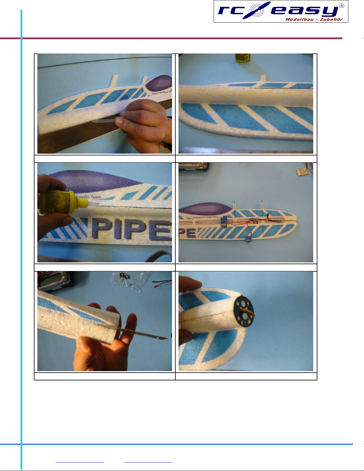
firewall. Do not forget to route the SC cables and solder them to your motor. Insert the motor into
the firewall, set a right thrust of 3-5°and fix by a CA glue. Cut out the stabilizer slot from the side
formers Fig 11. Bevel the elevator leading edge, use clear tape to attach to the stabilizer.
Picture
Insert the elevator and stab into the slot, check the geometry and glue in using styro CA Fig 12. In a
similar way proceed with the rudder fig 13, 14. Cut and glue control horns. Install carbon pushrods
fig 15, 16.
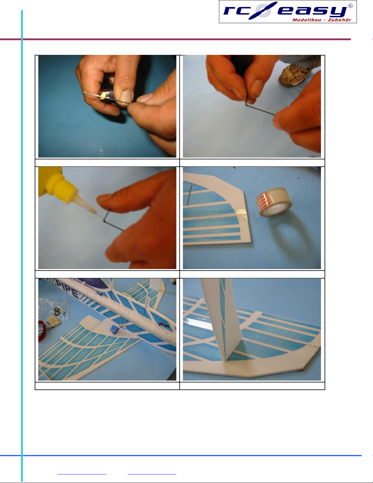
Recommended: most carbon rods can be bent after heating up. Use lighter or soldering iron for 1 to
2 seconds to soften the resin and bend the carbon wire Fig 17. Now we have a flexible joint that can
be used for instance to join the ailerons (further in this document) Fig 18. To stiffen the joint and
create a fixed bend, use drop of CA glue Fig 19.
Use 2 carbon rods with bends at their respective ends to make one complete pushrods. Glue
together with cca 20 mm overlap to achieve the right length of the bend. Such junction can be
always split apart using hobby knife and readjusted. The pushrods are routed through PP guides.
Fig 15.
Cut out ailerons from the wings, bevel their leading edges and reattach them using transparent tape.
Fig 20
Cut a servo hole in the lower wing. Lay the lower wing on a straight bench. Attach the fuselage using
styro CA Fig 21 Glue the wing struts to the lower wing Fig 22. Glue the PP „saddle“5x5x150 mm to
the upper wing Fig 23. Put the upper wing, the „saddle“ down, on the protruding carbon rods, attach
to the wing struts. Glue at several points Fig.24.
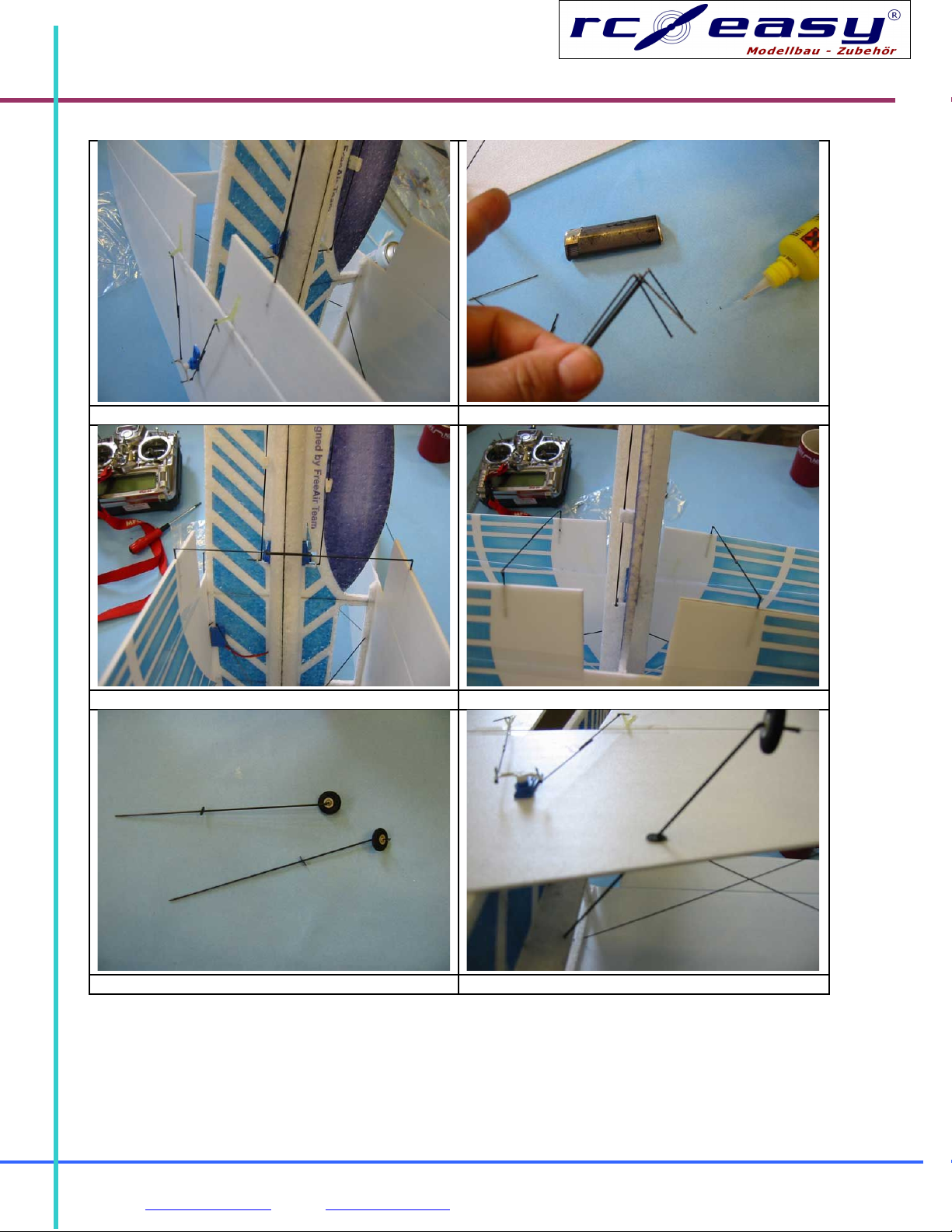
Use sand paper to sharpen the „flying wires“carbon rods at one end. Pierce the rods through the
wing at the top of the strut, towards the fuselage. Also from the middle of the upper wing down to
the strut at the lower wing Fig 25, 26. Check the geometry and use drops of styro CA to fix the flying
wires. Install the aileron servo Fig 27. Install control horns into the lower ailerons. Use 4 pieces of
carbon 1x60 mm to make the aileron pushrods adjust the lengths and glue together Fig 28, 29. Use
4 carbons 1x130 to connect the upper wing ailerons.
Use heat to bend them some 30 mm from their ends – you will get a flexible joint that will work as a
hinge Fig 30. Sand the shorter end sharp and run it into the aileron. Adjust the right length and glue
together the upper and lower rods together. After a control use a drop of styro CA to attach it to the
aileron Fig 31, 32. Increase the wheel axis holes to 1,6 mm diameter.
„Heat bend“the landing gear legs 1,5x20mm, fix the bend by a drop of CA. Install the wheels, use a
drop of CA to prevent the wheels falling off. Fig 33. Again, sharpen the other end of the legs. String
Donocik Handels und Leasing GmbH, Jägerweg 8, 85658 Egmating 3
Tel: +49 - (0)8095 - 2752 Fax: +49 - (0)8095- 8951