2
RC-TEK
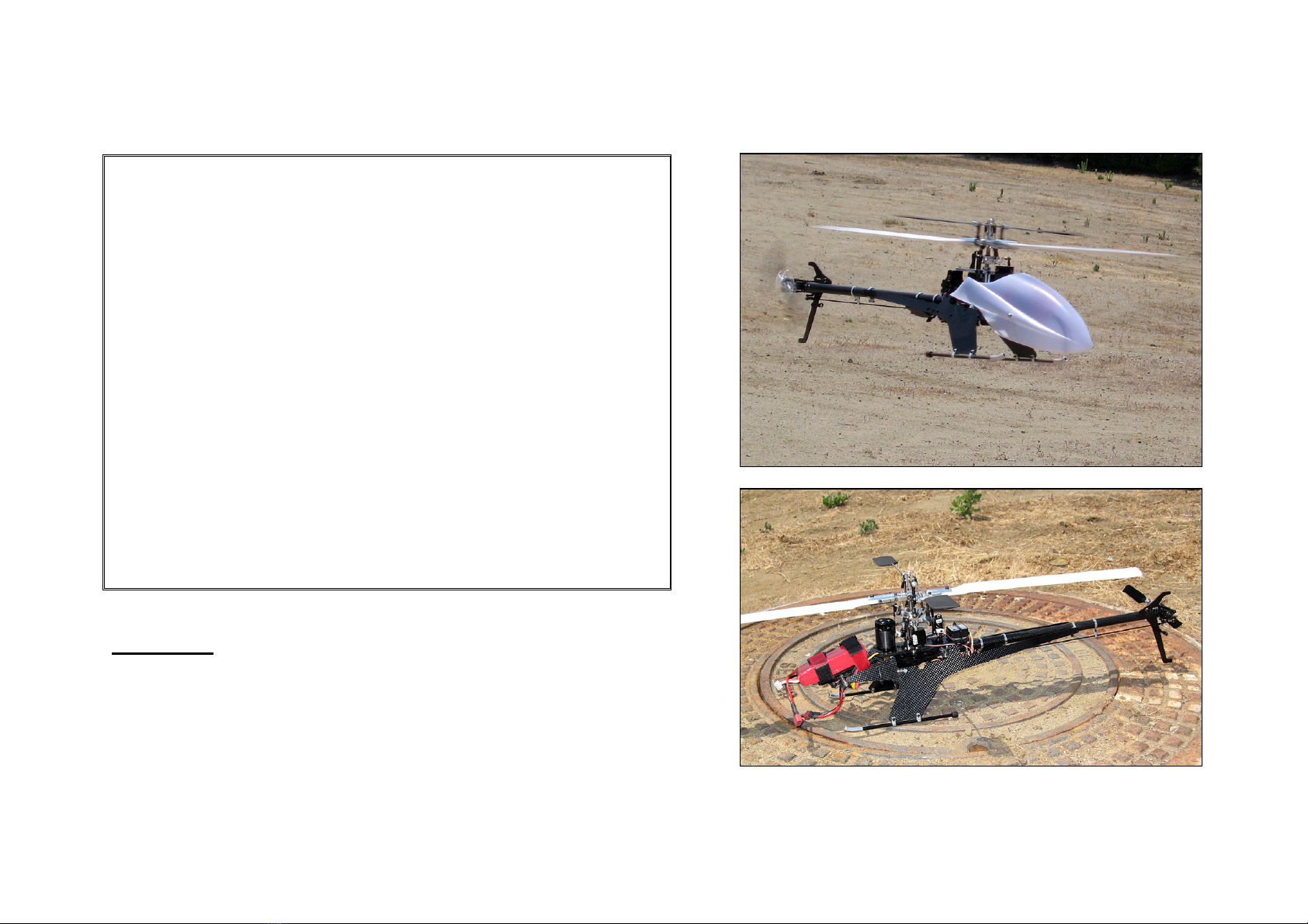
SJM325-C PRO SE Reference Manual
Thank you for your purchase of the innovative SJM325. In order to ensure proper operation of this high performance helicopter in a safe manner, please read
this reference manual completely before attempting to fly to the SJM325. Additionally, please observe all flying rules and flight precautions while fully
understanding the capabilities and limits of the SJM325. Be sure to retain this manual for future reference, routine maintenance, and tuning.
Assembly Tip: Use CA or loctite (#242) on all important screws throughout the SJM325 before fastening each screw.
Important Notes:
•The helicopter is recommended for skilled intermediate to advanced RC helicopter flyers.
•Make sure to read and follow all the instructions in this manual, including all accessories.
•Should any uncertainty arise, please consult with an experienced RC helicopter hobbyist and/or instructor BEFORE any attempt is made to fly this
helicopter.
•Always find an experienced and qualified secondary party to assist pre-flight inspection.
•Make sure the proposed flight vicinity is in an open space; free of crowds, obstacles, and buildings. Failure to abide may cause accidental and
potentially hazardous encounters.
•Any introductory flight should incorporate only basic maneuvers (hovering, linear ascending, and descending) until the stick feel is mastered.
•Do not operate the stock SJM325 325mm plastic blades above 3100RPM and/or the RC-TEK 325mm fiberglass main blades above
3300RPM.
Precautions:
•Fly only in safe areas, away from other people. Do not operate RC helicopters within the vicinity of homes or crowds of people. RC helicopters are
prone to accidents, failures, and crashes due to a variety of reasons including, lack of maintenance, pilot error, and radio interference. Pilots are
responsible for their actions and damage or injury occurring during the operation or as of a result of RC helicopter models.
Recommended Equipment NOT included in the SJM325 base kit:
•Radio Control System – 6 channels or more CCPM helicopter compatible transmitter or equivalent
•Receiver – 6 channels or more
•Gyro – RC-TEK 700/800 series, Futaba GY401, Logictech2100T
•Servos – (4) Servos – Hitec HS-81/85, Futaba S9650/S9257 or equivalent
•Battery – (1) 3S1P 1800mA+ Li-Po Battery (2200mA 25C or more recommended)
Copyright © 2008 RC-TEK/SGB Enterprises LLC. All Rights Reserved.