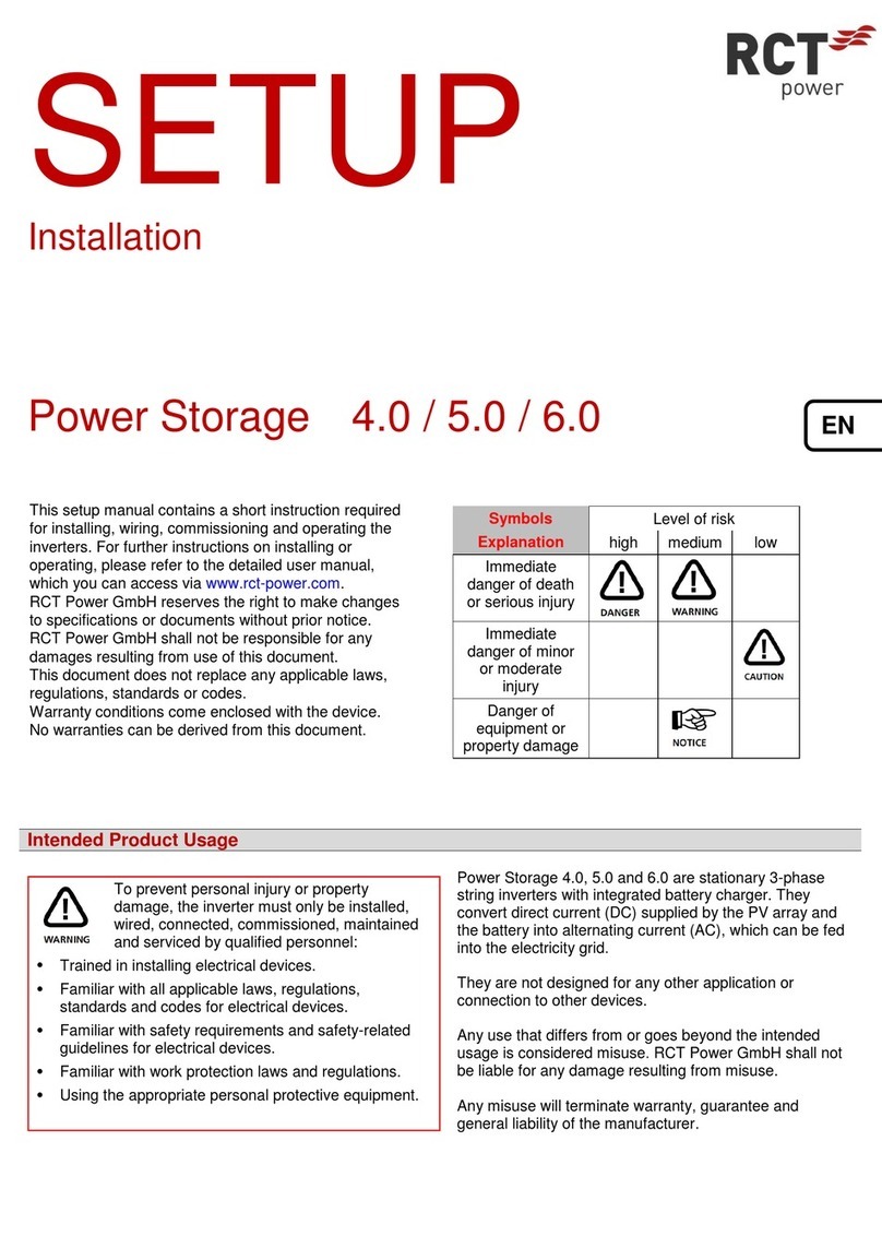
RCT Power Storage DC 8.0 User manual

MANUAL
Power Storage DC 8.0 / 10.0
EN

I
Copyright
Copyright © 2016 RCT Power GmbH. All rights reserved.
Any form of reproduction of this document in whole or in part without the written permission of RCT Power GmbH
constitutes a violation of EU and international copyright laws and will be prosecuted. This includes but is not limited to
duplication, distribution, translation or transmission by electronic or mechanical means, photocopying, recording or storage
on data carriers.
We explicitly reserve the right to make technical changes to improve the device or increase its safety standard. These
changes do not require a separate notification.
Responsible content editor: RCT Power GmbH
In this user manual, we refer to products and product names that are registered trademarks. This is done for information
purposes only and does not constitute a misuse of trademark regulations and laws.
The passages in the user manual referring to these products do not represent the product's original documentation.
About us:
RCT Power GmbH
Line Eid Str. 1
D - 78467 Konstanz, Germany
Tel.: +49 (0)7531 996 77-0
Mail: info[at]rct-power.com
Internet: www.rct-power.com
Document number: 03/2021

II
Table of contents
1ABOUT THIS MANUAL.........................................................................................................................................1
1.1 Validity, purpose and scope of this document and legal regulations.........................................................................1
1.2 Explanation of Symbols and References.....................................................................................................................1
2SAFETY INSTRUCTIONS........................................................................................................................................2
2.1 Personnel and Qualifications......................................................................................................................................2
2.2 Safety Procedures.......................................................................................................................................................3
3PRODUCT PRESENTATION ...................................................................................................................................4
3.1 Intended use...............................................................................................................................................................4
3.2 Product specification ..................................................................................................................................................5
3.2.1 Scope of supply...........................................................................................................................................................5
3.2.2 Component description..............................................................................................................................................5
3.2.3 Type plate and warning signs .....................................................................................................................................7
4MECHANICAL INSTALLATION...............................................................................................................................8
4.1 Select mounting location............................................................................................................................................8
4.2 Mounting ..................................................................................................................................................................10
5ELECTRICAL INSTALLATION................................................................................................................................11
5.1 Connections overview ..............................................................................................................................................11
5.2 AC connection...........................................................................................................................................................11
5.3 Configuration of the PV inputs .................................................................................................................................12
5.4 DC connection ..........................................................................................................................................................13
5.4.1 DC connector assembly ............................................................................................................................................14
5.4.2 DC Battery connection..............................................................................................................................................16
5.5 Disconnecting voltage sources .................................................................................................................................17
5.6 Additional Protective Conductor Connection...........................................................................................................18
5.7 Connection –Power Switch......................................................................................................................................18
5.8 Connection –Power Sensor......................................................................................................................................20
6COMMUNICATION PORTS.................................................................................................................................21
6.1 I/O circuit board .......................................................................................................................................................21
6.1.1 RS485 - X102 Interface .............................................................................................................................................22
6.1.2 Multifunction relay X100 Interface...........................................................................................................................22
6.1.3 Ripple control signals X101 Interface .......................................................................................................................23
6.1.4 Digital Inputs and Outputs X103 Interface ...............................................................................................................23
6.2 Connection Ethernet Interface.................................................................................................................................24
6.3 RJ45 connections for Power Battery, Power Sensor and Power Switch...................................................................25
6.3.1 Wiring the RJ45 interfaces........................................................................................................................................25
7COMMISSIONING..............................................................................................................................................26
7.1 Commissioning .........................................................................................................................................................26
7.1.1 Switch on the Inverter ..............................................................................................................................................26
7.1.2 Accessing the inverter ..............................................................................................................................................27
7.1.3 Configuring the Inverter ...........................................................................................................................................28
7.1.4 Setting Solar plant peak power and External power reduction................................................................................29
7.1.5 Configuring the Battery ............................................................................................................................................30
7.1.6 Configuring the Power Sensor (during operation) ...................................................................................................31
7.1.7 Expert Settings Battery.............................................................................................................................................32
7.1.8 Connecting the inverter to a network via a Wi-Fi connection..................................................................................34
7.1.9 Connecting the inverter to a network via an Ethernet connection..........................................................................37

III
7.1.10 Internet based remote access to the inverter..........................................................................................................39
7.1.10.1 Remote access via a FRITZ!Box with port forwarding and DynDNS .........................................................................39
7.1.10.2 Remote access via a FRITZ!Box by port forwarding and a MyFRITZ! account..........................................................46
7.1.10.3 Remote access via VPN using DynDNS or a MyFRITZ! account ................................................................................55
7.2 RCT Power APP Description......................................................................................................................................66
7.2.1 Overview of the RCT Power APP Menu ....................................................................................................................66
7.2.2 Detailed Description of the RCT Power APP Menu Items.........................................................................................67
7.2.2.1 Online .......................................................................................................................................................................67
7.2.2.2 History ......................................................................................................................................................................67
7.2.2.3 Device .......................................................................................................................................................................67
7.2.2.4 Network....................................................................................................................................................................69
7.3 Display ......................................................................................................................................................................70
7.4 Exporting RCT Power APP log data to MS Excel for further processing ...................................................................72
7.4.1 Abbreviations of the individual data records and their definitions..........................................................................72
7.4.1.1 Data records "Day” ...................................................................................................................................................72
7.4.1.2 Data records "Week" and "Month"..........................................................................................................................73
7.4.1.3 Data records "Year" and "Total"...............................................................................................................................73
7.4.2 Exporting Data records.............................................................................................................................................74
7.4.3 Importing RCT Power APP log data to an MS Excel spreadsheet .............................................................................78
8CONFIGURATION ..............................................................................................................................................81
8.1 Power reduction .......................................................................................................................................................81
8.1.1 Dynamic power reduction at the house connection point.......................................................................................82
8.1.2 Power reduction using a ripple control receiver ......................................................................................................83
8.2 Multifunction Relay ..................................................................................................................................................84
8.2.1 Multifunction Relay deployed in "Load" mode ........................................................................................................84
8.2.2 Multifunction Relay deployed in "Alarm" mode ......................................................................................................84
8.3 Configuration of the Emergency Stop Switch...........................................................................................................85
8.4 Configuration of the External Display.......................................................................................................................86
8.5 Networking ...............................................................................................................................................................87
8.5.1 Connecting a Power Storage DC and a Power Inverter to the same network..........................................................87
8.5.2 Connecting a Power Storage DC and third-party inverter to the same network .....................................................89
8.5.3 Connecting multiple RCT Power inverters in a LAN / WLAN network......................................................................91
8.5.3.1 Integration Master device ........................................................................................................................................92
8.5.3.2 Integration Slave device ...........................................................................................................................................94
8.5.3.3 System Visualisation.................................................................................................................................................96
8.5.3.4 Firmware update over network connection.............................................................................................................98
8.6 Increase battery capacity with additional battery modules (series connection) .....................................................99
8.6.1 Preparing the existing battery system....................................................................................................................100
8.6.2 Adding additional battery modules ........................................................................................................................103
8.6.3 Calibrating the new system ....................................................................................................................................103
8.7 Connecting a ModBus meter to the Power Storage DC (with or without radio transmitter module) ...................105
8.8 Software updates for inverter and battery ............................................................................................................107
9ERROR MESSAGES AND TROUBLESHOOTING ..................................................................................................107
10 MAINTENANCE................................................................................................................................................111
11 EXCLUSION OF LIABILITY .................................................................................................................................111
12 TECHNICAL DATA ............................................................................................................................................112

IV
PREFACE
Thank you for choosing the RCT Power Storage DC!
You have purchased an innovative, high-quality product with unique features and consistently high efficiency.
RCT Solar Inverters are transformerless, highly flexible and robust. With this device, you will always achieve the highest
possible yield from your PV system.
Solar modules, inverters, cables and other components of the photovoltaic system are
electrical devices. During installation, wiring, grid connection, operation, maintenance and
service they can cause various hazards.
Please read the documents supplied with the product carefully and follow the instructions
and device information to avoid material damage and personal injury.
Keep this manual in a safe place for future reference.
Declaration of conformity
RCT Power GmbH confirms that the Power Storage DC inverter described in this document is in compliance with the essential
requirements and provisions of the following European Union directives:
• RED Radio Equipment Directive (RED) 2014/53/EU
• Electromagnetic Compatibility Directive (EMC) 2014/30/EU
• Low Voltage Directive (LVD) 2014/35/EU
• Restriction of Hazardous Substances in Electrical and Electronic Equipment Directive (RoHS2)-2011/65/EU
The detailed declaration of conformity can be found under:
www.rct-power.com

1
1About this Manual
1.1 Validity, purpose and scope of this document and legal regulations
This document is valid for the Power Storage DC models 8.0 and 10.0.
Power Storage DC 8.0 and Power Storage DC 10.0 are referred to as "Inverter", "Hybrid Inverter", "Device" or "Product"
unless otherwise stated.
This installation manual provides general instructions for installing, wiring, commissioning and operating the inverter and the
battery.
The content of this manual is regularly updated and revised as a part of the continuous product development.
The current document version can be found at: www.rct-power.com.
We explicitly reserve the right to make technical changes which improve the device or increase its safety standard. These
changes do not require a separate notification. RCT Power GmbH is not liable for damages resulting from the use of this
document.
This manual does not supersede existing laws, regulations, rules, standards or conventions.
The warranty conditions are enclosed with the device. No further warranty claims can be derived from this document.
1.2 Explanation of Symbols and References
It is important to follow the references in the manual during the installation, operation and maintenance of the Power
Inverter. The table below shows the warning signs and symbols used in the manual.
Symbols and
References
Description
This symbol indicates a direct imminent danger. If the safety regulations are not observed,
this may result in death, personal injury or serious damage to property.
This symbol indicates a direct imminent danger of medium risk. If the safety regulations are
not observed, this may result in death, personal injury or serious damage to property.
This symbol indicates a direct imminent danger of low risk. If the safety regulations are not
observed, it might result in minor or moderate material damage.
This symbol indicates a potentially hazardous situation which, if not avoided, could result in
material damage to equipment or property.
This symbol indicates important information and hints. They will help you to better
understand the functionality of the Power Storage DC.

2
2Safety Instructions
2.1 Personnel and Qualifications
The inverter and the battery must only be installed, wired, connected, commissioned and
serviced by qualified personnel to prevent material damage or personal injury.
Qualified personnel authorised to perform the tasks described in this manual must have the following skills and technical
expertise:
• They are trained to install electrical equipment.
• They understand the technical functionality of an inverter
• They are familiar with lithium iron phosphate (LiFeP04) accumulators.
• They have read and understood the documents shipped with the unit.
• They know and use the appropriate tools and equipment to perform the tasks described in the manual.
• They are familiar with all current laws and applicable regulations, standards and directives for electrical equipment.
• They are familiar with the safety requirements and guidelines for electrical equipment.
• They are familiar with occupational health law and safety regulations.
• They know and use appropriate personal protective equipment.

3
2.2 Safety Procedures
The Power Storage DC was developed and tested in strict accordance with international safety regulations.
All safety instructions relating to electrical and electronic equipment must be complied with during installation, operation
and maintenance.
Danger to life or serious injury due to electric shock! High voltages are present in cables and
inner parts of the inverter if it is connected to the grid (AC / AC voltage source) or the solar
generator (DC / DC voltage source) is exposed to sunlight.
• Qualified personnel must perform any work that involves wiring, connecting or opening
the inverter case.
• Important: Both voltage sources (DC / solar generator and AC / grid) must be switched
off before any electrical work is carried out on the inverter.
• Turn the DC Switch into the 0 position to disconnect the DC voltage.
• Activate the circuit breaker or remove the fuse to disconnect the mains voltage (AC). Do
not reconnect until the work has been completed.
• To disconnect the battery voltage, both voltage sources (DC / solar generator and AC /
mains) must be switched off and the battery switch on the master must be set to "0".
• Allow a minimum of 10 minutes for the capacitors to fully discharge and then check the
voltage with a suitable measurement device.
• Ensure that other persons stay away from cables and internal components.
Risk of injury due to electric shock!
Installation, service and maintenance work must only be carried out by a qualified electrician.
• Do not drop the device. Do not expose it to knocks or pressure.
• Only switch on again after all electrical work has been completed.
Risk of burns on hot parts of the inverter enclosure.
Parts of the inverter enclosure can become hot during standard operation.
• Use care when touching the enclosure while the inverter is operating.
• Do not cover the Power Storage DC (especially not the top).
• All electrical installations must be carried out according to local and national standards
and guidelines.
• Contact your local energy supplier or grid operator before connecting the inverter to
the grid.
• Ensure that electrically conductive surfaces of the entire PV system are grounded to
prevent personal injury.
• A malfunction can impair inverter safety. Do not operate or start the inverter if it shows
visible damage or if the displayed error message is unclear.
• The inverter does not contain any parts to be serviced by the owner. Please contact
qualified personnel locally for servicing work on the inverter.
• Only use devices and accessories approved by the manufacturer. Do not make any
changes to the device. Do not remove the type plate.

4
3Product Presentation
3.1 Intended use
Power Storage DC 8.0 and 10.0 are stationary 3-phase inverters with integrated battery charging unit.
The energy received from the connected solar generator and the battery is converted into grid-compliant AC current and fed
into the grid. PV energy can also be charged directly into the battery on the DC side.
Please note:
The Power Storage DC is not designed for other use cases or connections to other devices.
Any deployment of the device that is different from the intended use is considered a misuse.
RCT Power GmbH is not liable for damages resulting from misuse of the device.
Any misuse terminates the warranty, guarantee and general legal liability of the manufacturer.
Fig.
3-1 Intended use of the Power Storage DC with the Power Battery in the PV system.
Pos
Description
Comment
A
PV Generator
Monocrystalline silicon; polycrystalline silicon and thin film without
grounding and protection class II
B
Battery
Power Battery 3.8, 5.7, 7.6, 9.6, 11.5
C
Inverter
Power Storage DC 8.0, 10.0
D
Household
Domestic electricity consumers
E
Power Switch
Switches to island operation mode in the event of a power failure.
F
Power Sensor
Current sensors for AC power measurements
G
Public grid
TT, TN-C, TN-S, TN-C-S

5
3.2 Product specification
3.2.1 Scope of supply
Our products are inspected for proper condition before shipment. Despite careful packaging, transport damage can occur.
The transport company usually has to take responsibility for this damage.
Please inform the transport company immediately if you notice any damage to the packaging or the Power Storage DC. Your
specialist dealer will be happy to assist you if necessary.
Do not install, wire or operate the Power Storage DC if any damage has been detected.
Check the contents of the shipment for completeness according to Fig. 3-2.
Fig. 3-2 Scope of supply
Pos.
Description
1
1x Power Storage DC
2
1x Inverter wall mounting bracket
3
4x PV Stick + (Weidmüller) , 4x PV Stick –(Weidmüller)
4
1x Setup manual
3.2.2 Component description

6
Fig. 3-3 Product specification
Pos
Description
Comment
1
LCD Operating Display
Displays important Inverter status and operational information (see
section 7.3)
2
Battery connection area
Battery connections (see sections 5.1 to 5.4)
3
RJ45-CAN bus communication
connectors
RJ45-sockets for CAN-bus connection with batteries, Power Sensor
and Power Switch
4
DC load break switch
Normal operation: Switch is in position "1", Turning switch to position
"0" shuts down the inverter.
5
DC connectors
Two separate Solar generator inputs (A & B),
Connector Plug Type : Weidmüller WM4
6
LAN-RJ45
RJ45- socket for connection to router (LAN)
7
Connection area additional
communication
Cable entry for the communication connections on the I/O-curcuit
board (see sections 5.1 to 5.4)
8
AC-connection
AC-connection cable entry
9
Type Plate
Contains technical data, serial number barcode and warning symbols
10
Additional protective
conductor connection
Connection for additional protective conductor (see section 5.6)

7
3.2.3 Type plate and warning signs
Fig. 3-4 Type plate
Pos
Description
1
Serial number
2
Technical data
3
Symbols
This symbol indicates that the user manual must be read and understood before the device
is put into operation.
After disconnecting the electrical connections, wait a minimum of 10 minutes before
opening the unit.
DC and AC voltage is present in the cables and inner parts of the inverter.
Hot surface! The housing can heat up during operation.
Warning!
High leakage currents. It is essential to establish an earthing connection before connecting
to the power supply circuit (AC mains)!
1
2
3

8
4Mechanical Installation
4.1 Select mounting location
Danger to life or serious injury from fire or explosions!
• Do not mount the inverter on a flammable surface.
• No combustible materials must be stored within 3 m of the inverter.
• The inverter must not be installed in areas and rooms subject to explosion hazards.
The mounting surface must be made of flame-retardant
material.
Do not install in rooms and area subject to explosion
hazards.
Keep away from flammable materials.
The inverter must be protected from dust, snow, rain
and direct thermal radiation (e.g. solar radiation,
central heating radiators, etc.).
The following requirements must be met:
• Relative humidity 5 ... 85 % (non-condensing).
• Ambient temperature -25 ... 60 °C
(40°C at full load).
• Maximum degree of contamination PD 2.
The mounting surface must be solid and able to
permanently support the weight of the inverter unit.
The selected location must be accessible easily and
safely at all times. Ensure no additional aids (e.g. ladder,
scaffolding) are required for access.

9
Mount the inverter in an upright or slightly
backward inclined position.
Required minimum distances to allow
sufficient free convection of air for cooling
the unit.
To prevent mutual heating, inverters must
not be mounted on top of each other.
Installation in a closed cabinet is prohibited.
• Ensure sufficient air convection for the inverter. Overheating of the inverter due to
poor cooling will result in reduced performance.
• The inverter can produce noise levels of up to 35db during operation. Ensure the
inverter is mounted in a way that people cannot be disturbed by the operating noise.

10
4.2 Mounting
Additional material required (not included in the scope of supply):
• At least 3 to 6 screws with a diameter of 6 to 8 mm.
• Suitable dowels.
• Suitable washers with a minimum outer diameter of 18 mm.
Procedure:
Mount the wall bracket as shown left.
Use at least 3 screws (ø 6-8mm),
3 washers (outside ø min. 18mm)
and the appropriate dowels.
Loosen the inverter's left and right-sided locking
screws at the top.
Hook the Power Storage DC with the retaining bolts on
both sides into the recesses of the wall mounting
bracket.
Tighten the locking screws again to secure the
inverter.
Check that the inverter is securely fastened.

11
5Electrical Installation
5.1 Connections overview
Fig. 5-1 Overview of wiring area and interior connecting components
Pos
Description
Comment
a
Battery connection area
Battery connectors, Connector Plug Type : Weidmüller WM4
b
RJ45-CAN bus communication
connectors
RJ45-sockets for CAN-bus connection with batteries, Power Sensor
and Power Switch
c
DC load break switch
Normal operation: Switch is in position "1", Turning switch to
position "0" shuts down the inverter when power circuit to battery
is interupted.
d
DC connectors
Two separate solar generator inputs (A & B), Connector type:
Weidmüller WM4.
e
LAN-RJ45
RJ45- socket for connection to router (LAN)
f
Connection area additional
communication
Cable entry for the communication connections on the I/O-curcuit
board (see sections 5.1 to 5.4)
g
AC cable gland
AC-connection cable entry
A
AC terminal block
AC terminal block with terminals for connecting phases L1, L2, L3,
as well as N and PE.
B
Terminals for DC parallel
connection
Terminals for internal wiring of the DC parallel connection of the PV
inputs (see section 5.3).
C
Communication circuit board
The communication circuit board has a serial RS485 interface, a
multifunction relay, 4 digital inputs for ripple control signals and
further digital inputs and outputs (S0) to connect current sensors or
displays.
5.2 AC connection
Procedure:

12
Danger to life or serious injury from electric shock!
• Only qualified personnel must carry out the work described in this section.
• Important: All voltage sources (DC /solar generator, DC /battery and AC /grid) must
be disconnected before carrying out any electrical work on the inverter.
• To disconnect the solar generator voltage, turn the DC switch (on the inverter) to
the position '0'.
• To disconnect the battery voltage, turn the DC switch (on the Power Battery Master)
to the position '0'.
• To disconnect the mains voltage (AC) activate the circuit breaker or remove the fuse.
Do not reconnect until the work has been completed.
• Only switch inverter back on after all electrical work has been completed.
• Ensure that other persons stay away from cables and internal components.
• Avoid traction forces on cables and plugs. Avoid sharp edges. Do not exceed the
maximum bending radius of the cables.
Danger to life or serious injury from electric shock or fire!
• Do not mix up the wires L, N and PE!
• Install an overcurrent protection device (circuit breaker, fuse) of max. 25A.
Required cable:
AWG 24 … 8
Remove the inverter cover and identify the AC terminal block
(see Fig. 5-1).
Loosen the cable gland of the AC cable duct. Carefully remove the
cable insulation.
Make sure that no wire strand is damaged. Use the designated cable
entry provided for the AC cable.
To open the terminals press them down with an insulated screwdriver.
Make sure that the connections of L1, L2, L3, N and PE are correctly
inserted.
Tighten the cable gland to ensure strain relief for the connected cable.
• Provide an AC disconnector switch. (LS switch 3-pole 6kA B characteristic 25A).
• Ensure that the disconnect device can be easily accessed at all times.
• Install the residual current device (RCD) or (RCCB) Type B required in the country of
installation. A residual current circuit breaker (RCCB) type A is sufficient for
installations in Germany.
5.3 Configuration of the PV inputs
A) Stand-alone operation Mode
Stand-alone operation mode is preconfigured. In this
mode, each DC input (A & B) has an independent MPP tracker.
This is especially beneficial if the properties of the PV-strings, such as module type, number of modules, orientation or
shading of the panels are different. Differences in these properties lead to different MPPs of the two PV-strings.

13
B) Parallel Mode
This mode is only used if several strings with the same number of modules are to be connected in parallel and the resulting
maximum input current per input exceeds 14 A.
Conditions for parallel mode:
• The total current of all strings connected to the inverter must not exceed 28 A.
• The strings have identical properties (module type, orientation and condition of the modules)
Example:
The PV panels are divided into three strings of 9A each. It is nevertheless possible to connect them to the inverter without
changing the string configuration. One string is connected to one of the two solar generator inputs. The other two strings are
connected in parallel via a Y contact and then connected to the remaining free input.
Procedure for parallel connection:
Danger to life or serious injury from electric shock!
• Only qualified personnel must carry out the work described in this section.
• Important: All voltage sources (DC /solar generator, DC /battery and AC /grid) must
be disconnected before carrying out any electrical work on the inverter.
• To disconnect the solar generator voltage, turn the DC switch (on the inverter) to
the position '0'.
• To disconnect the battery voltage, turn the DC switch (on the Power Battery Master)
to the position '0'.
• To disconnect the mains voltage (AC) activate the circuit breaker or remove the
fuse . Do not reconnect until the work has been completed.
• Only switch inverter back on after all electrical work has been completed.
• Ensure that other persons stay away from cables and internal components.
Material not included in scope of supply.
Required cable:
AWG 24 … 10
Remove the inverter cover.
Identify the terminals for parallel operation.
Connect terminal X101 with X104.
5.4 DC connection
Danger to life or serious injury from electric shock!
• A high voltage of up to 1000 V is applied to the DC cables while the PV system is
exposed to sunlight. Ensure that nobody touches the positive and negative cables at
the same time.
• The inverter is transformerless. Therefore, the PV array must not be earthed!
• Avoid traction forces on cables and plugs. Avoid sharp edges. Do not exceed the
maximum bending radius of the cables.

14
• Check the cables for correct polarity.
• Ensure the DC Switch is set to position "0" before connecting the connectors.
• The system voltage must not exceed the maximum input voltage of the inverter (see
Type plate). PV modules are suitable for a maximum system voltage according to IEC
61730 Class A.
Overvoltage will destroy the inverter.
If necessary, check the string layout to avoid an electrical surge.
• Any type of contamination (dust, moisture, etc.) negatively influences the
functionality of the connector system over the intended period of use. It is therefore
essential to avoid contamination during the connector assembly and installation.
• The voltage in the DC cables correlates with the intensity of the solar radiation onto
the PV array. It is lower in the morning and evening hours or when the PV panels are
shaded.
5.4.1 DC connector assembly
Prepare cable conductor :
Specialist cable for PV applications
PV Cable
2PfG 1169 / 08.07
Remove the cable insulation carefully.
Ensure that no individual strands are damaged.
Check the length of the exposed strands against the
plug.
Min. 15mm
Max. 16,5mm
Twist the strands

15
Inserting the cable conductor:
Do not turn connector plug in the screw fitting before
strands are wired.
Select the correct connector type.
Pay attention to the polarity.
Insert the cable in a straight line into the plug.
Ensure that the contact snaps into place audibly with a
"click".
Check that the connection has snapped in correctly
with a slight pull on the cable.
Conductor cable screw connection:
Turn connector plug in screw fitting.
Ensure that the DC switch is set to position "0".
Connect the corresponding positive and negative
poles to the DC inputs of the inverter.
Do not turn the DC Switch to position "1" until all
electrical work has been completed.
This manual suits for next models
1
Table of contents
Other RCT Inverter manuals
Popular Inverter manuals by other brands

SMA Solar Technology
SMA Solar Technology SUNNY BOY 1.5 operating manual

Sanken
Sanken S06-4A005-B instruction manual

Toshiba
Toshiba G7 quick start guide

Schweizer
Schweizer MSP-FR-EW Mounting instructions

enphase
enphase Microinverter System Reference manual

Benning
Benning DSP 2500 Operation and maintenance manual