FLAT-PAK™
SERIES
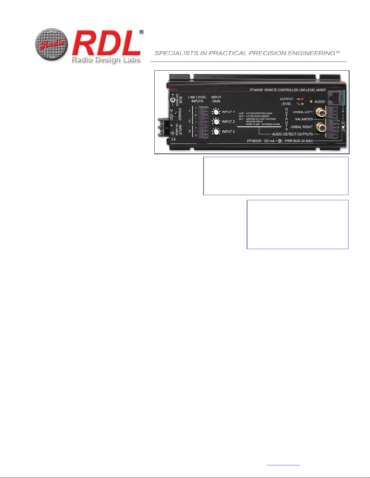
Model FP-MX3R
Remote Controlled
Line-Level Mixer
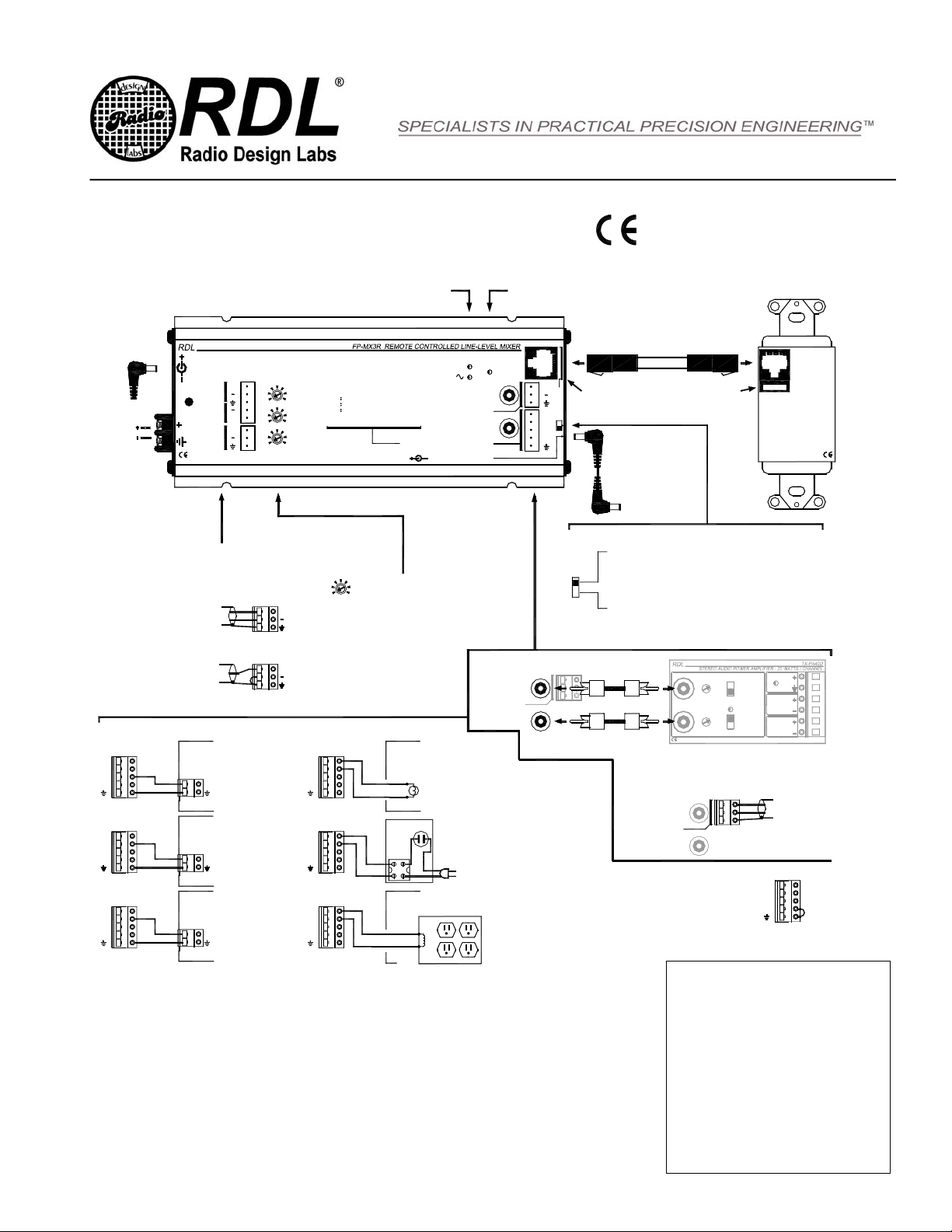
POWER
SOURCE
24 VDC
OR
Power to Additional
Flat-Pak Modules, Total
Current Not to Exceed 2 A or
Available Supply Current
D-RC2
D-RC2M
D-RC3
CONTROL
D-RC3M
NOTE: POWER FOR THE REMOTE
CONTROL IS PROVIDED FROM THE
MIXER THROUGH THE CABLE
TWISTED
PAIR CABLE
Mixing remote control jacks are color-coded light blue
Connect each input from a balanced or
unbalanced audio source.
+
+
BALANCED SOURCE
UNBALANCED SOURCE
With the corresponding input channel set to
maximum level on the remote control, set the
front-panel INPUT GAIN control for a proper reading
on the dual-LED VU meter (maximum green LED
intensity with minimum red LED activity)
Audio output level from the mixer is shown on dual-LED VU meter AUDIO LED glows when audio is detected. The "audio detect" outputs are triggered by
the detected audio and remain active 10 or 20 minutes following a loss of audio.
3
2
1
INPUTS
LINE LEVEL
+
+
S
T
U
P
T
U
O
INPUT 3
INPUT 2
INPUT 1
INPUT
GAIN
AUDIO DETECT OUTPUTS
BALANCED
UNBAL RIGHT
UNBAL LEFT
AUDIO
LEVEL
OUTPUT
+
L
R
T
C
T
M
R
3 CH
2 CH
FP-MX3R 120 mA
+4
PWR BUS 2A MAX
24 VDC
1A MAX
2A MAX INPUT
POWER
BUS
DLY
MUT
AUD
+24V
+
AUD LO FOR DETECTED AUDIO
MUT LO FOR AUDIO ABSENT
DLY GROUND DLY PIN TO EXTEND
RELEASE DELAY
NORM 10 MIN EXTENDED 20 MIN
3 CH
2 CH
SWITCH LOCATED IN THE MODULE END PLATE ACTIVATES OR
1) A 3 CHANNEL REMOTE CONTROL IS CONNECTED, OR
2) A 2 CHANNEL REMOTE CONTROL IS CONNECTED AND THE
THIRD MIXER INPUT (PAIR C) WILL NOT BE USED
(IN THIS POSITION, THE PAIR C INPUT IS DISABLED)
SET TO 2 CHANNEL REMOTE CONTROL POSITION IF:
A 2 CHANNEL REMOTE CONTROL IS CONNECTED AND THE
THIRD MIXER INPUT (PAIR C) WILL BE USED WITH
A LOCAL INPUT NOT REQUIRING GAIN ADJUSTMENT
(EXAMPLE: PAGING INPUT)
INPUTS
L
GAIN
R
POWER
24 VDC
INPUT MODE
STEREO
SUMMED MONO
THRESHOLD
UNBAL RIGHT
BALANCED
UNBAL RIGHT
UNBAL LEFT
Connect the balanced output to a balanced amplifier input, or
connect the left and right unbalanced RCA jacks to the L and R
unbalanced inputs of an amplifier. (Note: The unbalanced
outputs are mono; the dual jacks are provided for installation
convenience.)
BALANCED OUTPUT
AUDIO OUTPUT CONNECTIONS
UNBALANCED
BALANCED
LEFT
OUTPUT
OUTPUT
RIGHT
4 OHMS (2 x 15W)
8 OHMS (2 x 20W)
OUTPUT IMPEDANCE
COMPRESSOR/LIMITER
BALANCED
UNBAL LEFT
AUDIO DETECT / CONTROL OUTPUT CONNECTIONS
DLY
MUT
AUD
+24V
OEM AMPLIFIER WITH
EXTERNAL "MUTE" TERMINAL
(POWER DOWN AMPLIFIER
WHEN AUDIO NOT PRESENT)
MUTE / DISABLE AMPLIFIER
DLY
MUT
AUD
+24V
POWER OUTLET WITH
EXTERNAL CONTROL
TERMINALS TO TURN SYSTEM
AND / OR AMPLIFIER ON
GROUND TO ENABLE OUTLET
DLY
MUT
AUD
+24V
TRIGGER ANY RDL MODULE
WHEN AUDIO IS PRESENT
SLAVE DLY
MUT
AUD
+24V
ACTIVATE A CONTROL RELAY
WHEN AUDIO IS PRESENT
SOLID STATE
RELAY MODULE
EQUIPMENT
MAINS TO
RELAY MODULE
SOLID STATE
24 VDC
LAMP
24VDC RELAY COIL
DLY
MUT
DE-ACTIVATES INPUT PAIR C IF A 2 CHANNEL REMOTE CONTROL IS USED
SET TO 3 CHANNEL REMOTE CONTROL POSITION IF:
AUD
+24V
EXTERNAL LAMP OR LED
CONNECTION TO INDICATE
AUDIO PRESENT / SYSTEM
ACTIVE
DLY
MUT
AUD
+24V
DLY
MUT
AUD
+24V
THE "AUD" AND "MUT" OUTPUT CONTROL TERMINALS
SWITCH UPON DETECTION OF AUDIO ("AUD" SWITCHES
LOW; "MUT" RELEASES) AT THE MIXER OUTPUT AND
REMAIN IN THAT STATE UNTIL THE AUDIO HAS BEEN
ABSENT FOR 10 MINUTES AT WHICH TIME THEY TOGGLE
TO THE OPPOSITE STATE ("MUT" SWITCHES LOW; "AUD"
RELEASES). THE DELAY MAY BE EXTENDED FROM 10 TO
20 MNUTES BY INSTALLING THE JUMPER AS SHOWN
BETWEEN "DLY" TERMINAL AND GROUND.
NOTE: THE 24 VDC OUTPUT
TERMINAL IS PROTECTED BY
AN AUTOMATICALLY
RESETTING FUSE.
TYPICAL PERFORMANCE
Inputs (3): Balanced or unbalanced line level
Input Connections: Detachable Terminal Blocks
Input Signal Range: -20 dBV to +8 dBu, adjustable (for +4 dBu output)
Outputs (3): 150 Ωbalanced; 1 kΩunbalanced (2)
Output Connections: Detachable Terminal Block (balanced); RCA Phono Jacks (unbalanced)
Output Level: +4 dBu balanced, -10 dBV unbalanced
Frequency Response: 20 Hz to 20 kHz (+/- 0.25 dB)
THD+N: < 0.05% (20 Hz to 20 kHz); <0.02% (1 kHz)
Noise below +4 dBu: < -100 dB (all channels off); <-75 dB (any channel on); <-70 dB (all channels on)
Headroom above +4 dBu: > 18 dB
CMRR: > 50 dB (50 Hz to 150 Hz)
VCA attenuation: >90 dB (each input, remote control volume off)
Indicators (3): Dual-LED VU meter (2); Audio present (threshold = 35 dB below +4 dBu output)
Power Connections (3): Terminal block; dc power jack (2)
Power Requirement: 24 Vdc @ 120 mA plus connected control output loads, if any
Overall Dimensions: Height: 1.42 in 3.61 cm
Width: 3.25 in. 8.26 cm
Length: 8.14 in. 20.68 cm
Installation/Operation
EN55103-1 E1-E5; EN55103-2 E1-E4
Typical Performance reflects product at publication time
exclusive of EMC data, if any, supplied with product.
Specifications are subject to change without notice.
Radio Design Labs Technical Support Centers
U.S.A. (800) 933-1780, (928) 778-3554; Fax: (928) 778-3506
Europe [NH Amsterdam] (++31) 20-6238 983; Fax: (++31) 20-6225-287
891-2140A
NOTE: This equipment has been tested and found to
comply with the limits for a Class B digital device, pursuant
to part 15 of the FCC Rule. These limits are designed to
provide reasonable protection against harmful interference
in a residential installation. The equipment generates,
uses and can radiate radio frequency energy and, if not
installed and used in accordance with the instructions,
may cause harmful interference to radio communications.
However, there is no guarantee that interference will not
occur in a particular installation. If this equipment does
cause harmful interference to radio or television reception,
which can be determined by turning the equipment off an
on, the user is encouraged to try to correct the
interference by one or more of the following measures:
•Reorient or relocate the receiving antenna
•Increase the separation between the equipment
and receiver
•Connect the equipment into an outlet on a circuit
different from that which the receiver is
connected.
•Consult the dealer or an experienced radio/TV
technician for help.