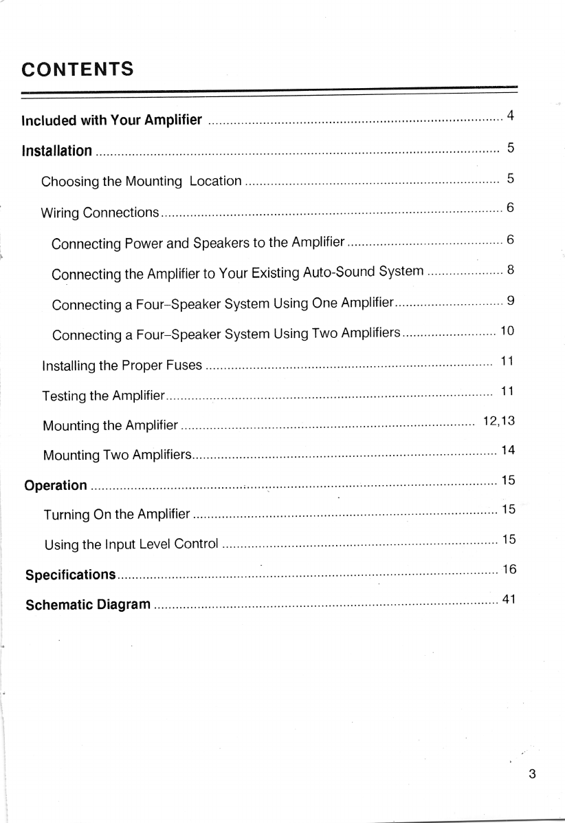
Realistic 12-1960 User manual

r '
I
I
:~~
S;0
-#
0IDS:7
75
~EALISt7C*
..
~
,l
',:
1>
:
·r
~
.
~
*Trademarks of Tandy Corporation

FEATURES
Your Beallstlc"80 +80 Watt Stereo
Power
Amplifier is
designed
to match
your automobile's existing stereo radio
or tape player system. Using a DC-to-
DC
switching power supply and high-
and low-level noise-isolated input, the
amplifier can
produce
crystal clear
sound
at
all
frequencies
with
minimum
distortion. '
Other features include:
•Automatic
On/Off
-automatically
turns
the
amplifier
on
or
off
whenever you turn your radio or
tape player system on or.off.
•Noise-Isolated Line-Level
RCA
Type Input
Jacks
-can accept
either high or low-level
hookup
from standard input jacks. This
enablesthe amplifierto match your
radio or tape player for the best
high-fidelity performance.
•Input Level Control -allows
you
to adjustthe input
level
to match
tile
output
level of
your
audio
system. Adjusts the input for
the
line-level or the speaker input.
' - .(
' 2
COPYRIGHT 1988, INTERTAN LTD.

CONTENTS
Included withYourAmplifier 4
Installation
,.,
", , ", 5
Choosing the Mounting Location...................................................................... 5
Wiring Connections ,.., , 6
Connecting Power and Speakers to the Amplifier 6
Connectinq the Amplifier to Your Existing Auto-Sound System 8
Connecting aFour-Speaker System Using One Amplifier 9
Connecting aFour-Speaker System Using Two Amplifiers 10
Installing the Proper Fuses 11
Testing the Amplifier
';
11
Mounting the Amplifier................................................................................. 12,13
Mounting Two Amplifiers 14
Operation , , " ;"." '.
.'
,..,,,,,,,".,,.,.., " 15
Turning On the Amplifier 15
Using the Input Level Control 15
Specifications., ,16
Schematic Diagram , 41
3

INCLUDED WITH
YOUR
AMPLIFIER
Your amplifiercomes with the following
itemsthat are necessaryfor connecting
and mounting. Besureto unpackthese
items before you dispose of the pack-
ing materials.
Mounting
Brackets
and
Hardware
4
Left-Bracket 1
Machine Screws 4
Flat Washer 4
Flat Washer 4
@
Right-Bracket. 1
Spring Washer 4
o
Sheet-Metal Screw 4
Spring Washer 4
o
Use these items to mount the amplifier
below the dash of your vehicle. See
"Mounting the Amplifier".

INSTALLATION
Note: You can connect this amplifier in
many different ways. You can even use
itwith
balanced
transformerless
(BTL)
circuitry. However, improper connec-
tions
can
damage
your
amplifier
and/orother components in your auto-
sound system.If,aftercompletelyread-
ing this manual, you do not feel confi-
dent about installing your amplifier and
have questions such as...
• Does my vehicle have a 12-volt
negative-ground electrical system?
• Which wire is the power wire?
• How do Iconnect a wire to the fuse
box?
...we strongly urge you to have your
amplifier installed by a professional
auto-sound installer.
CHOOSING THE MOUNTING
LOCATION
Wesuggestthat you connect thewiring
and confirm that the amplifier operates
properly with your system before you
actually
mount
it in
your
vehicle.
However,
you
should
choose
the
mounting location first. Then,when the
unit is connected and working proper-
ly, you can mount it without rerouting
the wires.
Choose amounting location
below
the
dash that:
• Is as
near
as
possible
to
your
vehicle's radio, tape player, or other
main auto-sound component
• Does not interfere with operation of
the vehicle
• Is not directly in front of a heating
vent
• Allows for drilling mounting holes,
without
damaging
other
vehicle
components
•
Allows
enough
leg
room
for
passengers
• Allows convenient and safe routing
of wires
Front Dash
Amplifier
Then,connect thewiring asfollows with
the amplifier as close as possible to the
chosen location.
5

6
WIRING CONNECTIONS
Caution: If the wiring harness (for
power and speakers) on your older ex-
isting radio/tape player is not com-
patible
with
your
new
Realistic
amplifier's wiring harness, we suggest
that you modify the existing wiring
using adapters available at your local
Tandy store. Or,
you
can have a
qualified technician modify the older .
wiring for you. Modifying your power
amplifier voids its warranty.
Connecting Power and
Speakers to the Amplifier
1. Before you make any connections,
disconnect the positive
(+)
wire
from your vehicle's battery. ·This
reduces the possibility of damage to
your system during installation.
Note:You must resetthe clock, digi-
taltuner memories for the radio, and
any other timer/memory devices
when you reconnect the battery wire
after wiring is complete.
2.
Connect
the
amplifier's
black
(ground) wire to a nearby part of the
vehicle's metal frame.
Note: .
Many
parts
of
modern
vehicles are made of plastic or other
materials
that
do
not
conduct
electricity. You must connect the
black wire to a metal part that is not
insulatedfrom the vehicle's frame by
one of these
non-conducting
parts.
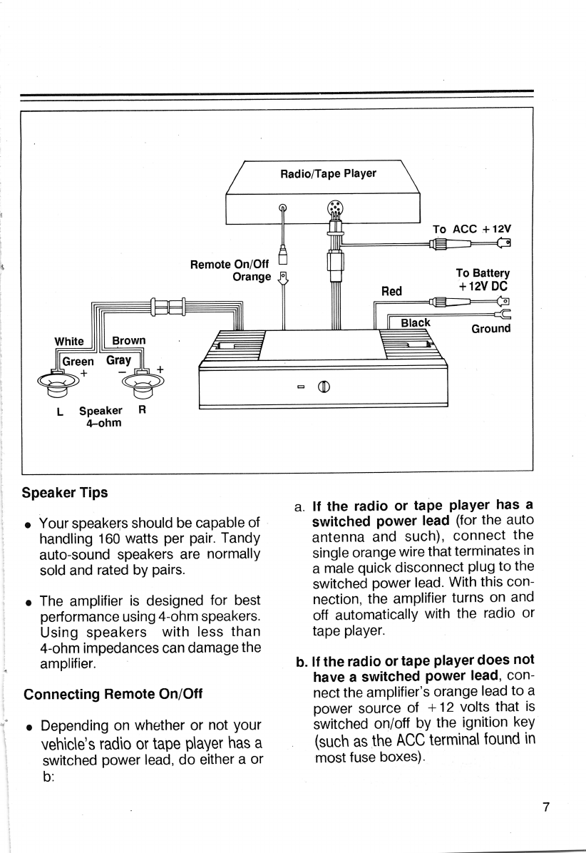
3. Connect the speaker
wiring
har-
ness(es)
(not
included)
to
the
speakers in your vehicle as shown
on Page 7.
Caution:
Ifyou useexisting speaker
wiring or if you run new wires, be
surethat chassis ground is not used
for any speaker connection. There
must be aseparate insulated wire for
each speaker connection
(+
and -).
4. Plug the speaker's wiring harness
into the amplifier.
5. Connect the thin red wire with in-line
fuse holder to ACCESSORY power
+12 volts which switches on and off
with the ignition key.
6. Connect the larger red (power) wire
with an in-line fuse holder directly to
the car battery +12 volts source.

Radio/Tape Player
White Brown
Remote On/Off
Orange 0
Red
Black
To ACC .+12V
To Battery
·t 12V
DC
Ground
LSpeaker R
4-ohm
Speaker Tips
• Your speakers should be capable of .
handling 160 watts per pair. Tandy
auto-sound speakers are normally
sold and rated by pairs.
• The amplifier is designed for best
performance using4-ohm speakers.
Using speakers with less than
4-ohm impedances can damage the
amplifier.
Connecting Remote On/Off
• Depending on whether or not your
veh\c\e's
radio
or
tape
p\aver
has
a
switched power lead, do either a or
b:
a. If the radio or tape player has a
switched power lead (for the auto
antenna and such), connect the
single orange wire that terrninates in
a male quick disconnect plug to the
switched power lead. With this con-
nection, the amplifier turns on and
off automatically with the radio or
tape player.
b. If the radio or tape player does not
have a switched power lead, con-
nect the amplifier's orange lead to a
power source of +12 volts that is
switched on/ott by the ignition key
(such
as
.the
ACC
terminal
found
in
most fuse boxes).
7

Connecting the Amplifier to Your Existing
Auto-Sound
System
Radio/Tape Player
8
If
the
existing
auto-sound
com-
ponent (radio or tape player) has
RCA-type line output jacks:
1. Connect the radio/tape player's line
outputs to the amplifier LINE INPUT
jacks using shielded cables with
RCA-type plugs. (Connect left to left
and right to right.)
2.
Disconnect
the
square,
in-line
con-
nectors
inthe
amplifier's
input
wiring
harness.
3. Insert the amplifier's input wiring
plug into the
mat~hing
jack on the
existing radio/tapeplayer (or into the
matchingjackthat you or a qualified
technician added
to
the
existing
component).
If
the
existing
aLito-sound
com-
ponent (radio or tape player) does
not haveRCA-type line outputjacks:
1. Be sure that the square, in-line con-
nectors in the amplifier input wiring
harness are securely connected.
2.
Insert
the
amplifier's
input
wiring
plug
into the matching jack on the exist-
ing radio/tape player (or .lnto the
...
matching jackthat you or a qualified
technician added
to
the
existing
component).

Connecting
A
Four-Speaker
System
Using
One
Amplifier
White Brown
Rear
Speaker
4-ohm
Ifthe source radio/tape player has both
high and low impedance output, you
canhavetwo pairsofspeakers.Usethe
front speaker output of the radio/tape
player
to
drive
the
front
pair
of
speakers,and, using the RCAhigh im-
pedance
output,
connect
the
amplifier's HIGH impedance input to
drive
the
powertut,
4-ohm
rear
speakers.
Radio/Tape Player
=
CD
To Battery
+12V DC
Ground
9

Connecting AFour-Speaker System Using Two Amplifiers
Radio/Tape Player
Ifyou want to havefour powerful,
4-ohm
speakers in your vehicle, you can use
two
amplifiers - one
for
the
front
speakers and one for the rear speakers.
Both amplifiers can be driven by the
HIGH
impedance
output
of
the
radio/tape player, using
two
Phone Plug
V-Adapters (Cat. No. 42-2438) con-
nected
to theleft andrightinputof each
amplifier respectively.
10

INSTALLING THE PROPER
FUSES
Fuse Holder
Ifthe fuse for your existing auto-sound
unit is not rated at 3 amps, replace the
fuse inthe amplifier's3-amp in-linefuse
with a fuse that matches the rating of
the existing unit's fuse.
TESTING THE AMPLIFIER
Before mounting the amplifier in the
location you chose earlier, we suggest
thatyou
reconnect
the
vehicle
battery's
positive(+) wire and test your entire
auto-sound
system.
See
"Operation
.".
11

12
MOUNTING THE AMPLIFIER
Attach the amplifier as follows in the
location you chose prior to connecting
the wiring. You can unplug the wiring
harnesses to make mounting more
convenient.
1. Attach the left and right mounting
brackets to the sides of the amplifier
as shown.
2. Using the brackets as a guide, mark
the locationsfor the mounting holes.
3. Drill 5mm holes in the marked loca-
tions, using care not to damage any-
thing on the opposite side of the
mounting surface.
4. Removethe mounting brackets from
the amplifier and attach them to the
mounting surface using the supplied
sheet-metal·screws.
5. Attach the amplifier to the brackets
and plug in the wiring harnesses.

13

MOUNTING TWO AMPLIFIERS
Use
theillustration belowasa
gUide
for installing two
amplifiers.
14

OPERATION
TURNING ON THE
AMPLIFIER
Once you connect the remote control
wire coming from the amplifier to the
auto antenna wire, from radio or tape
player, the amplifierturns on automati-
cally whenever you turn on
your
radio
or tape player. Otherwise, the amplifier
turns on with your ignition. The power
indicator lights when the amplifier is
operating.
USING THE INPUT LEVELJ
CONTROL
The INPUT LEVELcontrol allowsyou to
adjust the fevel of the audio signal that
enters the amplifier. To adjustthis con-
trol
for
optimum performance, follow
these steps:
1. Adjust the INPUT LEVEL control on
your
power
amplifier
fully
counterclockwise.
2. Turn on
your
stereo system and turn
up the volume about one-third of its
full range.
3. Rotate
the
INPUT LEVEL control
clockwise until you can hear the
program.
4.
Tum
up the volume on
your
stereo
until the program begins
to
distort.
Then, immediately turn the volume
down
to the point at which the dis-
tortion began.
5. Rotate the INPUT LEVELcontrol until
the
volume is at the maximum level
you want
your
system
to
produce.
6. Rotate
your
stereo's volume control
to reduce the volume to a confort-
able listening fevel.
15

SPECIFICATIONS
Maximum Output Power 80
watts
per
channel
(with 4-ohm speakers connected).
60 watts per channel (at 1% distortion
with 4-ohm speakers connected)
Power Band Width 20-30,000 Hz,
(at -3dS, 50 watts output)
Input Level
High Impedance 130mV
Low Impedance 4.0V
SIN Ratio gOdS (at 50 watts, 1kHz, A-weighted)
Load Impedance 4-ohm per speaker terminal
Separation 60dB
Current Drain 25A Maximum
Power Supply Vpltage
DC,
14.4V Negative Ground
Dimensions 38 x220 x190mm
Weight 1.8 Kg
16

INTR0DUCTI0N
'Votre amplificateur de
puissance
stereo
deux
fois
80
watts est
concu
pour
completer
avantaqeu-
sement
l'installation
stereo
de votre vehicule.
Grace
a
une
alimentation CC a
CC
automatique
et
a
une
entree
antibruit a
haut
et abas
niveau
,l'arnplificateur
peut
produire
un
son
d'une
purcte
cristalline a
toutes
les fn3quences,
avec
une
distorsion minimale.
CARACTERISTIQUES
•Mise
sous/hors
tension
automatique.
Le simple fait de mettre
sous/hors
tension
votre
auto-
radio ou lecteur de cassette met
automatiquement
en/hors
fonction l'amplificateur de puissance.
•Prises d'entree'de type CINCH, niveau ligne, antibruit.
Permettent
la
connexion
a
haut
ou
bas niveau
avec
des
prises
d'entree
standard.
Ceci
petmet
al'amplificateur de tirer le meilleur
rendement
de votre installation.
•
Reglage
du
niveau
d'entree,
Vous
permet
d'ajuster Ie niveau
d'entree
afin de
l'adapter
au ni-
veau
de sortie de votre installation. Ajuste I'entrce au
niveau
ligne ou haut-parleur.
TABLE
DES
MATIERES
Fournitures
livrees
d'origine
avec
votre
amplificateur
........................
..
18
Montage
' , . . . . . . . . . . . . . . . . . . . . . . . . . . . . . . . . . . . . 19
Choix de
l'emplacement
~
'. . . .
..
19
Branchement
" . . . . . . . . . . . . . . . . . . . . . . . . . . . . . . . . . .
..
20
Connexion
de l'alimentation et
des
haut-parleurs
al'amplificateur 20
Connexion
de l'amplificateur al'installation existante '.
..
22
Branchement
d'une
installation a
quatre
haut-parleurs
avec
un seul amplificateur 23
Branchement
d'une
installation a
quatre
haut-parleurs
avec
deux
amplificateurs " . 24,
Mise en
place
des
fusibies . . . . . . . . . . . . . . . . . . . . . . . .
..
25
Test 25
Montage
d'un
amplificateur ',' . . . . . . . . . . . . . . . . . . . . . . . . . . . . . . . . . . .
..
26
Montage de
deux
arnplificateurs ' . . . . . . . . . . . . 27
Fonctionnement
....................................................... 28
Mise en
marche
de l'amplificateur '.
..
28
Utilisation du n2gIage du niveau
d'entree
'.
..
28
Donnees
techniques
. . . . . . . . . . . . . . . . . . . . . . . . . . . . . . . . . . . . . . . . . . . . . . . . . .
..
28
Schema
41
17

r
FOURNITURES
LIVREES
D'ORIGINE
AVEC
VOTRE
AMPLIFICATEUR
Votre amplificateur est livre avec les
composants
suivants.necessaires
au
montage
et au branche-
ment. Veillez adisposer de
tout
ce materiel avant de jeter les emballages.
Supports de
montage
et
accessoires
Support
gauche.
................
..
1
Vis parker . . . . . . . . . . . . . . . . . . . . . . . 4
Rondelles plates 4
@
Rondelles plates 4
@
18
Support
droit . . . . . . . . . . . . . . . . . . .
..
1
Rondelles aressort 4
Vis guidees ...................... 4
Rondelles aressort 4
o
Utilisezces
composants
pour
monter
l'ampli-
ficateur
sous Ietableau de bord de votre
veh
i-
cule . Referez -vous au
paragraphe
«Montage
de l'amplificateur» .

MONTAGE
Remarque:
vous
pouvez
connecter
cet am-
plificateur de
differcntes
maniercs
.
Vous
pou-
vez me me l'utiliser avec des circuits sans trans-
formateur
equilibres.Toutefois, un
branche-
ment
incorrect risque d
'endommager
votre
amplificateur
ainsi
qued'autres
composants
de
votre installation .voiture. Si
apres
lecture
de
.ce
manuel,
vous
n'
etes
pas
certain de
pouvoir
mener
a
bien
Ie
montage
de cet
amplificateur
au
si
vous
demandez,
par
exemple.
• .Si
votre voit ure a
une
installation elec-
trique
de 12Vavec masse
negative
.
•
quel
est Ie cable d' alimentation
•
comment
s'
opere
Ie
raccordement
a
la
boite
a
fusibles,
nous
vous
conseillons de
confier ce travail
a
un techicien qualifie.
CHOIX
DE
L'EMPLACEMENT
Nous vous
suggerons
d'effectuer les con-
nexions et de
vous
assurer
que
l'amplificateur
fonctionne parfaitement avec votre installation
avant
de
proceder
ason
montage
dans
votre
vehiculc. La
premiere
chose
afaire toutefois
est de
determiner
un
emplacement
de
mon-
tage. Puis ,
une
fois
que
vous
avez
branchc
les
filset
que
vous
etes sur de
son
bon fonction-
nement
, vous pouvez Iemonterdefinitivemcnt
sans
qu'il soit besoin de retirer
tous
les filsen
place.
19
Choisissez un endroit
sous
Ietableau de
bard
,
qui:
• soit
aussi
pres que
possible
de votreauto-
radio,lecteur de cassette,... ;
• n'interfere
pas
sur Iebon fonctionnement du
vehicule
;
• ne soit
pas
directement
en face d
'une
bou-
che
d'aeration ;
• n'exige
pas
de forer des trous risquant d'en -
dommage
r
des
pieces du vehicule, .
• laisse un
espace
suffisant
pour
lesjambes du
passager
;
•
permette
un
branchement
aise des fils.
TABLEAU DE
BORD
AMPLIFICATEUR
Effectuez
ensuite
Ie
branchement
en
tenant
l'amplificateur aussi pres
que
possible de l'em-
placement
choisi
pour
son
installation.

BRANCHEMENT
Attention! Si les fils (d'
alimentation
et de
con-
nexion
aux
haut-parleurs)
de
votre
installation
existante
ne
sont
pas
adaptes a
ceux
de
votre
nouvel
amplificateur
,
nous
vous
suggerons
d'utiliser
des
adaptateurs
disponibles
dans
vo-
tre
magasin
Tandy
.
Vous
pouvez
aussi
de-
mander
l'aide
d'un
technicien
pour
modifier
Ie cablaqe
existant.
Nous
attirons
votre
atten-
tion
sur
Ie fait
que
toute
modification
de
l'arn-
plificateur
annule
automatiquement
sa
garan-
tie .
Connexion
de l'alimentation et
des
haut-parleurs al'amplifi-
cateur
1.
Avant
d'effectuer
la
premiere
connexion
,
veuillez
debrancher
Ie fil positif (
+)
de la
batlerie du vehicule afin
d'eviter
d'endom-
mager
votre
installation
durant
Ie
monta-
ge.
Remarque:
Tout
appareil
(horloge,...) de
votre
vehicule
devra
evidemment
etre
re-
gIe lorsque
vous
rebrancherez
Iefilala bat-
terie.
2.
Branchez
Ie fil noir (masse)
de
l'amplifica-
teur
sur
une
piece
proche
du chassis du ve-
hicule.
Remarque:
Un
certain
nombre
de
com
-
posants
dans
Ies vehicules actuels
sont
faits
de
plastique
ou
d'un
autre
materiau
non-
conducteur
electrique
.Veuillez
connecter
Iefilnoir a
une
piece
mctallique
qui ne soit
pas
isolee
du
chassis
par
l
'un
de
ces
com-
posants
non-conducteurs.
3. Si ce n'est
deja
fait
,effectuez les con-
nexions
aux
haut
-parleurs.
Attention!
Que
vous
utilisiez Ie
cablaqe
existant
ou
que
vous
connectiez
de
nou-
veaux
fils
avos
haut-parleurs
,assurez-vous
de
ne
pas
employer
la
masse
du
chassis
pour
Ie
branchement.
Veuillez utilisez un
filisole
separe
pour
chaque
connexion
de
haut-parleur
(+
et -).
20
4.
Branchez
la tresse
des
filsde
connexion
des
haut
-parleurs
a
l'arnplificateur.
5.
Branchez
Ie fin fil
rouge
avec
porte-fusible
en ligne
sur
la
borne
d
'alimentation
+
12V
ACC
du
demarreur
,ce
qui
permettra
une
mise
sous/hors
tension
de
l'amplificateur
apartirde la
de
de contact du vehicule.
6.
Branchez
Ie large ftl
rouge
(alimentation)
avec
porte-
fusible
en
ligne
directement
sur
Ia
batterie
12VCC
.
Table of contents
Languages:
Other Realistic Amplifier manuals
Popular Amplifier manuals by other brands

International Rectifier
International Rectifier IRAUDAMP17 Reference design

Magnet
Magnet PR-9R user manual

Kicker
Kicker KXMA Series owner's manual

axing
axing Basic-line SVS 1-00 Operation instructions

Altec Lansing
Altec Lansing 1270 POWER AMPLIFIER Specifications

Open House
Open House ChannelPlus H511HHR manual