RADIO SHACK LIMITED WARRANTY
This equipment is warranteed against defects for 2 years from
date of purchase. Within this period, we will repair it without
charge for parts and labor. Simply
bring your sales slip
as proof of
purchase date to any Radio Shack store. Warranty does not cover
transportation costs. Nor does it cover equipment subjected to
misuse or accidental damage.
This Warranty gives you specific legal rights and you may also have other
rights which vary from state to state.
We Service What We Sell
SPECIFICATIONS
Two (Left & Right),
with separate controls for each
+0. 5
5 to 100,000 Hz
dB
—1.0
.± 12 dB @60,240,1000,3500 and
10,000 Hz
0.02% @0.775 volts output
0.02% @0.775 volts output
(20-20,000 Hz)
80 dB (2.45 volt input)
Up to 10 volts RMS
0 dB
: 75 K ohm
:
10 ohm
:
MAIN IN, TAPE MON itor
: MAIN OUT, TAPE OUT
Power Switch (indicated with L.E.D.),
10 Linear Sliding Frequency Controls
(5 each channel), Tape Monitor Switch
120 volt AC, 60 Hz, 10 watts for UL
& C.S.A. models (220/240 volt AC,
50 Hz 10 watts for European and
240 volt AC, 50 Hz 10 watts for
Australian models)
Number of Channels
Frequency Response
(flat setting)
Tone Control Range
Intermodulation Distortion
Harmonic Distortion
Hum and Noise (shorted input):
Dynamic Range (flat setting) :
Total Gain (flat setting)
Input Impedance
Output Impedance
Inputs
Outputs
Controls
Power Requirements
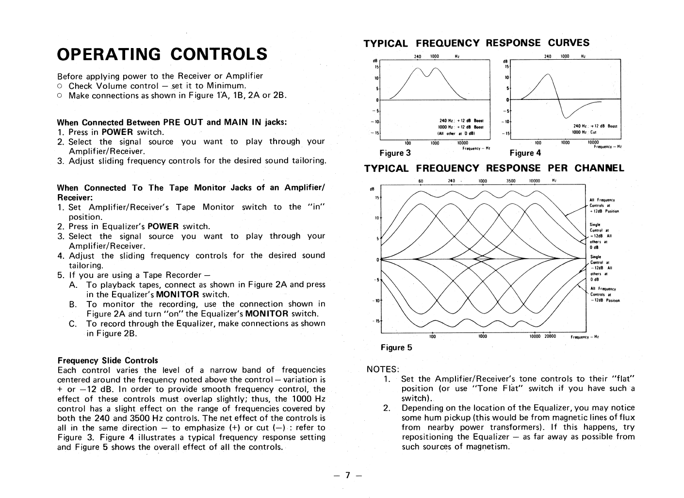
The
REALISTIC Stereo Frequency Equalizer
is designed to tailor
the frequency response of your stereo system. Since it has separate
controls for each channel, it gives you an almost infinite combination
of control variations. The controls each have a range of approximately
24 dB (.± 12 dB) and are marked in 4 dB increments.
There are many reasons why you need such a specialized component.
The speakers, the room, your ears and your personal preferences vary
greatly. For example, if a speaker is simply moved 6 to 8" (15 to 20
cm) away from the wall, the bass response at 50 Hz could drop as
much as 8 to 10 dB.
The furnishings in the room, such as stuffed chairs, draperies and
floor covering can affect the high and middle frequency response
very dramatically.
It is a known fact that our hearing changes with age and varies
greatly from person to person or if the sound pressure or volume is
decreased. The ear's low frequency response at low volume can drop
as much as 15 dB at normal conversational levels.
Normal Tone Controls vary too much of the audio spectrum.
If
we
want to increase the low bass, we also increase the middle bass which
very often muddies up the whole bottom end. The same is true with
the treble control.
We cannot boost or cut the midrange without affecting the entire
high frequency response.
The Frequency Equalizer with its five frequency ranges can give
almost an infinite number of possible frequency response variations.
It will allow you to match your speakers to your room and the music
to your ears — without adding distortion, hum or hiss.
The Equalizer can also be used when making recordings of old LP's
or 78's without losing the main portion of the music. It can get rid of
the scratchy top, add a little needed bass • • • and really bring some of
those old 78's alive again.
The circuit of the Equalizer is a new type of tone control circuit
which yields extremely low distortion. The components used are of
the highest quality and we wish you many years of good sound.