Rear view safety RVS-77535 User manual

Reverse With Condence ™ 1
360° Surround View Camera System
RVS-77535
Instruction Manual

Rear View Safety
2
TABLE OF CONTENTS
Introduction...............................03
SafetyInformation..........................04-06
Before Beginning Installation. . . . . . . . . . . . . . . . . . . . . . . 07
BriefIntroduction. . ......................... 08
ProductFeatures...............................9
Applications ............................10-11
SystemCheck.............................12-13
WiringDiagram.............................14
Cameras Distribution..........................15
Wiring........................... 16-17
CameraInstallation......................... 18-27
CameraCalibration......................... 28-33
UserSettings............................ 34-41
VideoRecording........................... 42-43
PowerManagement......................... 44-45
PackingList................................ 46
Specification......................... 47
Troubleshooting......................... 48-49

Reverse With Condence ™ 3
NOTE! Please read all of the installation instructions
carefully before installing the product. Improper
installation will void manufacturer’s warranty.
Congratulations on purchasing a Rear View Backup
Camera System!
With this manual you will be able to properly install and
operate the unit.
The Backup Camera System is intended to be installed as a
supplement aid to your standard rear view mirror that already exists
in your vehicle. The Backup Camera System should not be used as a
substitute for the standard rear view mirror or for any other mirror
that exists in your vehicle.
In some jurisdictions, it is unlawful for a person to drive a
motor vehicle equipped with aTV viewer or screen located forward of
the back of the driver’s seat or in any location that is visible, directly
or indirectly, to the driver while operating the vehicle.
INTRODUCTION

Rear View Safety
4
Please read the entire manual and follow the instructions and
warnings carefully. Failure to do so can cause serious damage and/or
injury, including loss of life. Be sure to obey all applicable local
trac and motor vehicle regulations as it pertains to this product.
Improper installation will void manufacturer’s warranty.
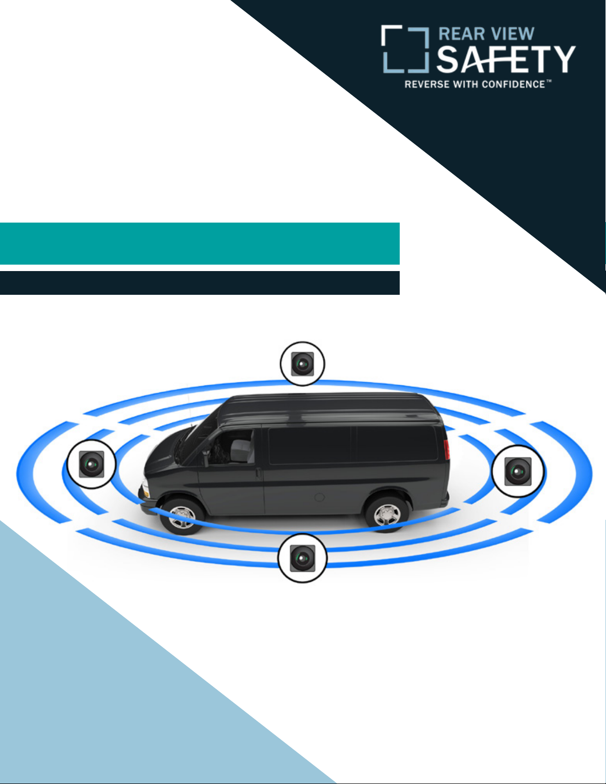
• The Rear View Camera System is
designed to help the driver safe-
ly detect people and/or objects
helping to avoid damage or injury.
However, you the driver, must use it
properly. Use of this system is not a
substitute for safe, proper or legal
driving.
• Never back up while looking at the
monitor alone. You should always
check behind and around the vehi-
cle when backing up, in the same
way as you would if the vehicle did
not have the Rear View Camera
System. If youbackupwhilelooking
only at the monitor, you may cause
damage or injury. Always back up
slowly.
•The Rear View Camera System is
not intended for use during exten-
sive back-up maneuvers or backing
into cross trac or pedestrian walk-
ways.
•Please, always remember, the area
displayed by the Rear View Camera
System is limited. It doesnot display
the entire panorama behind you.
USAGE:
SAFETY INFORMATION

Reverse With Condence ™ 5
•Electric shock or product
malfunction may occur if this
product is installed
incorrectly.
• Use this product within
the voltage range specied. Failure
to do so can cause
electronic shock or product
malfunction.
• Take special care when
cleaning the monitor.
•Make sure to rmly ax the prod-
uct before use.
• If smoke or a burning smell
is detected, disconnect the
system immediately.
• Where the power cable may touch
a metal case, cover the cable with
friction tape. A short circuit
or disconnected wire may cause a
re.
• While installing the Rear View
System be careful with the wire
positioning in order to avoid wire
damage.
• The Rear View System should only
be used when the vehicle is in
reverse.
• Do not watch movies or
operate the monitor while driving;
as it may cause an
accident.
• Do not install the monitor
where it may obstruct drivers
view or obstruct an air bag
device.
• Dropping the unit may cause
possible mechanical failure.
INSTALLATION:
SAFETY INFORMATION

Rear View Safety
6
If you have questions about this product, contact:
Rear View Safety
1797 Atlantic Avenue
Brooklyn, NY 11233
Tel: 1.800.764.1028
IN NO EVENT SHALL SELLER OR MANUFACTURER BE
LIABLE FOR ANY DIRECT OR CONSEQUENTIAL DAMAGES OF
ANY NATURE, OR LOSSES OR EXPENSES RESULTING FROM
ANY DEFECTIVE PRODUCT OR THE USE OF ANY PRODUCT.
SAFETY INFORMATION

Reverse With Condence ™ 7
Before drilling please check that no cable or wiring is on the other side
of the wall. Please clamp all wires securely to reduce the possibility
of them being damaged while vehicle is in use. Keep all cables away
from hot or moving parts and electrical noisy components.
We recommend doing a benchmark test before installation
to insure that all components are working properly.
Step 1: Choose the monitor and camera locations.
Step 2: Install all cables in vehicle, when necessary a 0.8 (20mm)
hole should be drilled for passing camera cable through vehicles
walls. Install split grommets where applicable.
Step 3: Once all cables and wiring have been properly routed, perform
a system function test by temporarily connecting the system. If the
system seems to not be operating properly see troubleshooting (page
48-49).
BEFORE YOU BEGIN

Rear View Safety
8
System Introduction
The 360° Surround View Camera system synthesizes images from four
cameras to create a true 360° view of the vehicle’s surroundings.
This omni-directional perspective creates a bird’s eye view of
the vehicle.
Because this system generates a complete view of your vehicle and its
surroundings, blind spots are eliminated. This view assists with park-
ing, helps the driver navigate narrow roads, and helps with turning.
The system oers various connection types, including HDMI and AV.
It also features both 2D and 3D views.
The RVS-77535 is also a fully functional DVR, capable of 24 hour loop
recording.
INTRODUCTION

Reverse With Condence ™ 9
Product Features
• Four 190° ultra wide sh-eye cameras
• Seamless video merging based on dual core ARM CPU and
high eciency acceleration engine
• Adjustable viewing angle in 3D mode
• Advanced sh-eye distortion correction
• Automatic brightness adjustment for each camera
• 3D video deinterlacing and noise reduction technology for CVBS
signal decoding
• MicroSD card/USB disk support
• Simple calibration procedure with included calibration tape. The
system will work on most types of vehicles
• Power management system to preserve vehicle battery
• Available 1080p video resolution
• OEM quality
PRODUCT FEATURES

Rear View Safety
10
APPLICATIONS
Main Application
Side Parking Reverse Parking
Narrow Roads
Blind Spot Coverage Turning Assist

Reverse With Condence ™ 11
APPLICATIONS
Product Features
3D & 360° seamless merging
360° blind spot coverage
Adjutable viewing angle in 3D mode
Flexible omni-directional monitoring
Fish-eye distortion correction
Guided camera calibration
Other Functions
Video recording
24 hour parking monitoring
G-sensor triggered recording
Reverse Parking
Proof of Fault in Accidents Car DVR
Crowded Roads

Rear View Safety
12
SYSTEM CHECK
1. Wire Routing Inside The Car
Please refer to wiring diagram for more details. Each cable is color cod-
ed. Wire routing from cameras to the control box .
2. Camera Installation
Please refer to the corresponding section for installation steps.Wheth-
er side cameras are embedded or installed outside depends on the size
of the side mirrors and available installation space. Be careful when
disassembling the side mirrors and drilling installation holes under the
plastic cover.
3. Control Box Installation
It is strongly recommended that the Control Box is installed inside/be-
hind the glove box, or in another location that allows easy access to the
microSD card/USB disk.
4. Wiring Test
Double check all wire connections before turning on the system. Do
not plug in control box until you are sure wiring is correct.

Reverse With Condence ™ 13
SYSTEM CHECK
5. Functionality Test
Before using the system, please perform a functionality test on the
main functions.
6. Camera Calibration and Image Merging
The system menu provides a step by step camera calibration guide.
Once all the calibration information is collected the software will auto-
matically complete the video merging.
7. Side Camera’s Angle Adjusting
Adjust the side camera’s angle until the calibration tape overlaps the
reference guide line on the screen.
8. Troubleshooting
How to x wire connections, cameras and host device.

Rear View Safety
14
WIRINDG DIAGRAM
Wiring Diagram
Control Box

Reverse With Condence ™ 15
Cameras Distribution
CAMERAS DISTRIBUTION
Perspective Drawing

Rear View Safety
16
WIRING

Reverse With Condence ™ 17
WIRING
Front Camera
1. Disassemble the glove box/central panel
2. Distribute the front camera cable from the logo position along the
original wire distribution tube to the glove box/central panel.
Rear Camera
1. Take out the trunk inner panel.
2. Distribute the rear camera cable from the license plate lamp along
the original wire distribution tube to the glove box/central panel.
Left and Right Camera
1. Disassemble the side mirrors.
2. Take glass lens o side mirrors, and then distribute side camera ca-
bles from the original tube of side mirrors to the inside of the front
doors.
3. Distribute cables from inside the front doors to the glove box/central
panel.
Instructions on how to disassemble the glass lens of side mirrors: In general, most Japanese cars have a
plastic-buckle structure for side mirrors, the top buckle is“L”shaped, and the bottom buckle is U-shaped.
Gently insert a at plastic screwdriver in the bottom middle of the glass to safetly remove it.Take extra
care, as glass is very fragile. German cars have a dierent side mirror design, but the disassembly steps
are very similar.

Rear View Safety
18
CAMERA INSTALLATION
Front camera installation method:
1. Insert the front camera in the cen-
ter of the front vehicle logo.
2. Connect the front camera to the
extending cable.
3. Double check the eld of the view
from the system preview menu win-
dow and adjust accordingly.
4. Using screws and the metal pad
accessories, x the front camera to
the car.
Camera Installation Demonstration For Honda
Note: Dierent car models work dierently
with various cameras types. Installation loca-
tion may vary. Please see model installation
drawings.

Reverse With Condence ™ 19
CAMERA INSTALLATION
Installation method for front camera:
1. Insert the front camera to the center of the front vehicle logo.
2. Connect the front camera to the extending cable.
3. Double check the eld of the view from the system preview menu
window and adjust accordingly.
4. Using screws and the metal pad accessories, connect the front cam-
era to the car.
Camera Installation Demonstration Of Universal Front Camera

Rear View Safety
20
CAMERA INSTALLATION
1. Take o the trunk inner panel and Ieft license plate LED.
2. Place rear camera locating plate on the left side of license plate lamp,
then drill a wiring hole. Remove locating plate after drilling is complete.
3. Distribute rear extending cable from the license plate lamp along the
original wire distribution tube to the glove box.
4. Connect rear camera extending cable to 12V anode of the reversing
lamp to create a reversing signal.
5. After testing the video from the connected camera, place the trunk
inner panel back in the vehicle.
Rear Camera Installation Demonstration (Honda Specic)
Table of contents
Other Rear view safety Camcorder manuals