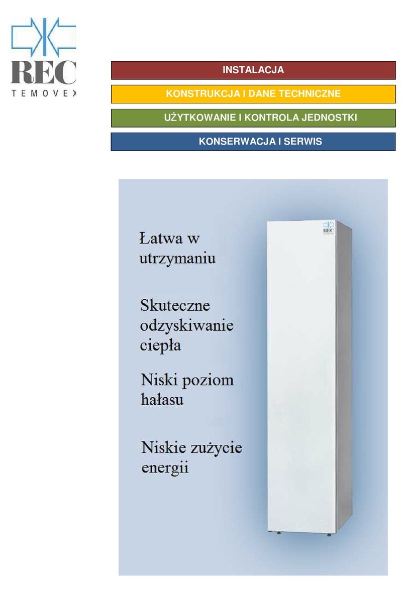
REC Temovex RT 400S-EC Instruction Manual

Air Handling Unit RT 400S-EC
REC Indovent AB, Box 37, 431 21 Mölndal | tel. 031-675500 | www.rec-indovent.se
OPER ATION & MAINTENANCE INSTRUCTIONS
INSTALLATION
CONTROL PANEL
Easy to
maintain
Effi cient
heat
recovery
Low noise level
Low energy
consumption
Easy to
maintain
Effi cient
heat
recovery
Low noise level
Low energy
consumption

OPERATION & MAINTENANCE
CONTENT Air handling unit RT 400S-EC
Safety ........................................................page 3
General/System descriptions .....................page 4
Principle of operation .................................page 5
Control panel, structure,
simple adjustments .................................page 6-9
Replacing filters, maintenance ............ page 10-12
Troubleshooting ....................................... page 14
Components/Technical data ............... page 15-17
Wiring diagram ........................................ page 18
INSTALLATION
Delivery receipt ........................................ page 19
Setting up/Installation/Duct system ....page 20-21
Starting up/Adjustment ....................... page 22-25
Maintenance/Servicing .......................page 26-27
Troubleshooting .......................................page 28
CONTROL PANEL
Basics ..................................................... page 29
Temp. setting for incoming (supply) air .....page 30
Changing operating mode ....................... page 30
Afterheater on/off ....................................page 30
Remot panel ........................................... page 31
Regulation accuracy - heating ................. page 32
Heat recovery on or off ............................ page 32
Summer bypass, bypass .........................page 32
Cooling on or off (optional) ....................... page 33
Settings, cooling ......................................page 33
Resetting filter alarms .............................. page 32
Outdoor air temperature ..........................page 34
Extract air temperature ............................page 35
Program version ......................................page 35
Adjusting the supply air flow ....................page 36
Adjusting the extract air flow ....................page 36
Bypass restriction .................................... page 37
Adjusting the circulation air flow ............... page 37
External control, input 1 ...........................page 38
External control, input 2 ...........................page 38
Timer functions, channel 1 (optional) .......page 39
Timer functions, channel 2 (optional) .......page 39

3
REC Indovent AB, Box 37, SE-431 21 Mölndal, Sweden | tel. +46 31 675500 | www.rec-indovent.se
OPERATION & MAINTENANCE Air handling unit RT 400S-EC
REC-E08.10
Safety
Read through theese instructions carefully.
Pay particular attention to the safety texts marked with an
exclamation mark above.
If you use and look after your ventilation unit correctly, it
will serve you well for a long time to come. You will enjoy
a superior indoor climate while at the same time saving
energy thanks to high recovery levels.
Save theese instruction carefully. They might be needed
in the future.
Installation
Work carried out by laymen may impair the performance
of the ventilation unit and cause injury or damage to
property. If the unit is adjusted incorrectly, it will not be
possible to achieve the desirable benefits such as satis-
factory air quality and maximum energy savings.
The unit is heavy. Edges and corners which you would
not normally come into contact with may be sharp.
Therefore, it is a good idea to wear gloves when moving
the unit.
Keep an eye on children. An uninstalled
unit may easily tip over under an abnormal load.
Cleaning
Keep the unit clean to ensure maximum performance and
a long service life. Filters must be replaced as specified in
the instructions. The unit must not be operated without the
intended original filters. Operation without filters will have
a serious impact on unit performance and may damage
the unit’s fans and heat exchanger. The intended filters
can be ordered from REC Indovent AB,
www.recvent.se.
The heat exchanger must be cleaned as described in
the instructions. Only detergents designed for use on
aluminium may be used.
Alkaline detergents containing ammonia, caustic
soda, etc. must never be used as these will corrode the
aluminium surfaces and so destroy the heat exchanger.
Service and maintenance
Servicing and repairs, alongside normal maintenance,
should be carried out by ventilation specialist or - if
electricity is involved - an authorised electrician.
The electric panel must not be opened by anyone
other than an authorised specialist.
The protective cover in front of the fan cowlings must not
be removed while the unit is operational as this poses a
risk of contact with moving parts. Before opening, make
sure that the unit is not connected to the mains power
supply (the plug is pulled out or the fuse removed).
Working on the system may affect the warranty terms for
the unit.
Only use original spare parts.
Scrapping
Prevent accidents when the unit is scrapped. Remove
the cable from the wall socket and cut it as close to the
unit as possible. Store and transport the scrapped unit
lying down.
Comply with the instructions of your municipality when
dropping off the unit for recycling.

4
Frånluft Avluft
Uteluft
Tilluft
REC Indovent AB, Box 37, SE-431 21 Mölndal, Sweden | tel. +46 31 675500 | www.rec-indovent.se
OPERATION & MAINTENANCE Air handling unit RT 400S-EC
REC-E08.10
General/Introduction
REC Indovent has been manufacturing Temovex air
handling units since the 1970s.
User-friendliness has been the order of the day right from
the outset. For us, one of the most important things is
to make sure our users feel secure and can handle the
minimum of maintenance with no fuss. And of course, the
fact that you also demand market-leading performance
as regards energy consumption and recovery is also a
natural consideration in our ongoing development work.
Our amassed experience has all been combined to
create your Temovex unit.
Temovex units are a quality product made in Sweden,
with a long service life and extreme reliability with no
unpleasant surprises.
And just to prove that our efforts are taking us in the
right direction, Temovex units have won first prize in
the Swedish Energy Agency’s technology development
competition, looking for the best ventilation heat
exchanger. The motto for the competition was as follows:
“To save energy and the environment with inexpensive,
efficient, reliable ventilation heat exchangers”.
To ensure your entire ventilation system maintains its
performance throughout its entire design service life, you
should follow the simple maintenance instructions in this
booklet.
This unit is designed for continuous operation. It should
only be shut down for servicing or inspection.
The unit must never be operated with no
filters fitted.
System descriptions
Operation principle
The Temovex unit
The Temovex unit
consists of fans, air filters,
afterheaters and a highly
efficient counterflow heat ex-
changer developed by our-
selves. The counterflow heat
exchanger is very well sealed,
which prevents odours, con-
taminants, etc. from coming
back into the home.
A long service life, low
operating costs and a low
maintenance requirement are
ensured thanks to the use of
top quality, reliable compo-
nents and design solutions
involving few moving parts. The thermal energy in the
air sucked out of the building is transferred in the heat
exchanger to the fresh air coming into the building. The
Temovex unit retains the heat or coolness in the building
without supplying new thermal energy. (Compare this
with a thermos.) Making the most of the thermal energy
already present in the building allows the operating
time and/or size of the conventional heating system to
be reduced. Comfort is also enhanced because the air
entering the home is at a temperature nearer to room
temperature than it would have been if the air had been
taken in directly from outdoors. At the same time, the
indoor environment is really enhanced because all the
air entering the building passes through a fresh air filter
(outdoor air filter). One filter also makes maintenance
easy. With Temovex it’s easy to access!
5
REC Indovent AB, Box 37, SE-431 21 Mölndal, Sweden | tel. +46 31 675500 | www.rec-indovent.se
OPERATION & MAINTENANCE Air handling unit RT 400S-EC
REC-E08.10
The principle for a balanced ventilation system, with
mechanical supply and exhaust air, is really simple.
To get rid of anything that could harm people and/or
buildings, we need to remove contaminants and moisture
held in the indoor air. This is known as exhaust air (green
ducts). This creates underpressure in the building, so
new air has to come in.
When mechanical supply air is provided, there is an
opportunity to filter the new air and also to check sound
incoming from the outside (the blue duct). Mechanical
supply air (red ducts) allows you to determine where you
want the fresh air to be, in what quantities and at what
temperature. Normally you want this air to go to rooms
people spend time in, such as bedrooms and living
rooms.
Well thought out distribution of exhaust/supply air results
in a home well ventilated throughout. And you get a more
consistent indoor temperature throughout the entire
home into the bargain, too.
The used air which has now released most of its energy
Principle of operation - REC Vent ventilation system
content, is fed out in a separate ventilation duct for extract
air (brown duct). Most commonly, this opens out into a
roof hood on the roof, but a wall-mounted wall device
can just as well be used. A balanced ventilation system
almost always comes with heat recovery.
Temovex units make your home into a thermos! You retain
the heat/coolness in the building without supplying new
thermal energy. Your heating system will have an easier
job to do, and you will be able to adapt it according to
“the conditions in the thermos”. The kitchen fan is often
dealt with entirely separately, with an individual fireproof
duct in a roof hood on the roof.
REC Vent is a complete ventilation system, including duct
components and planning, supplied by REC. We take
overall responsibility for the operation and quality of this
system. And so we can guarantee you the results you
require.
Contact your building supplier or local ventilation
contractor and tell them you want a REC Vent ventilation
system. We promise you will be pleased with the results!

6
PULS REG
SPEED
AUTO/MIN/
MAX/STOP
MIN EAIR
DEFROST
REM ALM
EXH AIR
VERSION
BP L LIM
MIN SAIR
REC Indovent AB, Box 37, SE-431 21 Mölndal, Sweden | tel. +46 31 675500 | www.rec-indovent.se
OPERATION & MAINTENANCE Air handling unit RT 400S-EC
REC-E08.10
Structure/explanations
Menu structure
Control panel
On the following pages you will find detailed instructions
on how to set the unit according to your requirements
and wishes. The unit control system optimises its function
according to the settings you define.
As a user of the ventilation unit, you will find it useful to be
aware of the following:
In menus where you have the option of making changes,
“auto mode” gives the most optimised function. If you
select a manual setting, On or Off, the manual setting
takes precedence over the auto settings. Push and
briefly hold the buttons to implement changes. You
can also hold down a button longer to browse.
The lighting in the display turns on automatically when
pushing a button and turns off again after about 1 minute
of activity.
Buttons
Menu button, press to return to the main menu.
Arrow up, move up in menus or change mode
Arrow down, move down in menus or
change mode
OK, confirm selected setting
Indicator lamps och symbols
Alarm, comes on when an alarm is triggered -
look in the display for more detailed information
Bypass, comes on when the bypass is open
(no recovery)
Afterheater, comes on when the afterheater
is heating
Change mode, comes on when changes can
be made
Display
• Fan speed selected
• Air temperature
Starting up/main menu
The display shows:
Line 1: current fan speed, min. flow/auto/max. flow
Line 2: actual air temperature in the supply air duct.
Note: As an alternative, sensors can be installed in
exhaust air ducts or rooms.

7
SET TEMP
20°
REC Indovent AB, Box 37, SE-431 21 Mölndal, Sweden | tel. +46 31 675500 | www.rec-indovent.se
OPERATION & MAINTENANCE Air handling unit RT 400S-EC
REC-E08.10
Temperature, setting the temperature of
incoming air (supply air)
• In the main menu
• Pressure
• The display shows: “SET TEMP” and current
setting. The change mode lamp comes on.
Press up or down to give the required
value is displayed, in increments of 1 °C (set
your required room temperature)
• Confirm your selected setting by pressing .
This takes you back to the main menu, and
current values are displayed.
Changing operating mode, fan speed
• In the main menu
• Press arrow down up until
“SET MODE” appears in the display
• Confirm by pressing , AUTO appears in the display.
• The change mode lamp comes on. Use
arrow up or down to switch between
auto/min flow/max flow/stop system.
• Confirm your selected setting by pressing .
This takes you back to the main menu.
Simple adjustments Extended adjustments
SET
MODE
Afterheater on/off (automatic if so required)
• In the main menu
• Press arrow down up until
“MANUAL SETTINGS” appears in
the display
• Confirm by pressing ,
“HEATER” appears in the display
• Confirm by pressing . The current setting appears
in the display. The change mode lamp comes on.
Use arrow up or down to
choose between on/off (AUTO/OFF)
• Confirm your selected setting by pressing .
• Press the menu button to go back
to the main menu.
MANUAL
SETTINGS
HEATER
HEATER
AUTO

8
REC Indovent AB, Box 37, SE-431 21 Mölndal, Sweden | tel. +46 31 675500 | www.rec-indovent.se
OPERATION & MAINTENANCE Air handling unit RT 400S-EC
REC-E08.10
Remote panel (option)
When the remote panel is connected, the text in the unit’s
control panel changes to “REMOTE”.
Structure/descriptions
The alarm LED indicates filter change.
M = Change fan speed: Auto, High or Low
+ = Increase the temperature of supply air
– = Decrease the temperature of supply air
Temperature adjustment
By pressing + or – you can adjust the temperature of
the supply air a few degrees up or down in relation to the
setting in the unit’s main panel.
MANUAL
SETTINGS
REM ALM
Alarm indication
You can choose whether you want to have alarm indica-
tion on the unit or on the remote panel. When you switch
on the power to the unit, the alarm lamp flashes once
if alarms are displayed on the remote panel. To change,
the M button must be depressed at the same time as
the power is switched on. 3 flashes: Alarms on remote
panel are off. 4 flashes: Alarms on remote panel are on.
To reset the filter alarm from the remote panel, push and
hold M and - (minus) at the same time; the lamp will
flash 6 times.
Alarm indication on unit
• On the main menu
• Press the down or up until
the display shows ”MANUAL SETTINGS”.
• Confirm with .
• Press the down or up until
the display shows ”REM ALM”
• Confirm with .
• Displayen visar nuvarande inställning. The current
setting is shown on the display. The change mode
lamp comes on. Use the up/down arrows
to choose between YES/NO. NO provides indication
on the unit. YES provides no indication on the unit.
• Confirm your selected setting with .
• Press the menu button to return to the main menu.
Note: Through a combination of settings on the unit and/
or remote panel, a situation can arise in which alarms are
not displayed on either unit.

9
REC Indovent AB, Box 37, SE-431 21 Mölndal, Sweden | tel. +46 31 675500 | www.rec-indovent.se
OPERATION & MAINTENANCE Air handling unit RT 400S-EC
REC-E08.10
Regulation accuracy, afterheater
• In the main menu
• Press arrow down or up until
“MANUAL SETTINGS” appears in
the display
• Confirm by pressing .
• Press arrow down once until
“HTR SPAN” appears in the display
• Confirm by pressing .
• The current setting appears in the display.
The change mode lamp comes on. Use
the arrows up/down to change the value by
1-5 °C. State the deviation from set room temperature
in “SET TEMP” before the afterheater is activated. (4
°C is
recommended, e.g.: you require
21 °C indoors. So you set this value to 4.)
• Confirm your selected setting by pressing .
• Press the menu button to go back
to the main menu.
Heat recovery on or off
• In the main menu
• Press arrow down or up until
“MANUAL SETTINGS” appears.
• Confirm by pressing .
• Press arrow down twice until
“HEAT REC” appears in the display
• Confirm by pressing .
• The current setting appears in the display.
The lamp change mode lamp comes on. Use
the arrows up/down to choose from
on/off/auto (ON= heat recovery always on,
OFF= heat recovery always off,
AUTO= optimises the function
guided by selected temperature settings)
• Confirm your selected setting by pressing .
• Press the menu button to go back
to the main menu.
Setting summer bypass (bypass)
(Cooling recovery: Bypass closes to reuse subnormal
temperature when the outdoor temperature exceeds
the settings SET TEMP + REC SPAN)
• In the main menu
• Press arrow down or up until
“MANUAL SETTINGS” appears.:
• Confirm by pressing .
• Press arrow down three times until
“REC SPAN” appears in the display
• Confirm by pressing .
• The current setting appears in the display. The lamp
change mode lamp comes on. Use the arrows
up/down to change the value by 1-5 °C. Specifies
the deviation from the set room temperature in “SET
TEMP” before the bypass opens
(3 °C is recommended, e.g.: you
require 21 °C indoors.
So you set this value to 3.)
• Confirm your selected setting by pressing .
• Press the menu button to go back
to the main menu.
MANUAL
SETTINGS
HTR SPAN
MANUAL
SETTINGS
HEAT REC
MANUAL
SETTINGS
REC SPAN
HTR SPAN
4
HEAT REC
AUTO
REC SPAN
2

10
REC Indovent AB, Box 37, SE-431 21 Mölndal, Sweden | tel. +46 31 675500 | www.rec-indovent.se
OPERATION & MAINTENANCE Air handling unit RT 400S-EC
REC-E08.10
Cooling on or off, optional
• In the main menu
• Press arrow down or up until
“MANUAL SETTINGS” appears
in the display
• Confirm by pressing .
• Press arrow down or up until
“CHILLER” appears in the display
• Confirm by pressing .
• The current setting appears in the display. The lamp
change mode lamp comes on. Use the arrows
up/down to choose from off/auto
(OFF = cooling is never activated,
AUTO = optimises the function according to
the selected temperature settings)
ON = cooling always on
• Confirm your selected setting by pressing .
• Press the menu button to go back
to the main menu.
MANUAL
SETTINGS
CHILLER
Settings – cooling
• In the main menu
• Press arrow down or up until
“MANUAL SETTINGS” appears
in the display
• Confirm by pressing .
• Press arrow down or up until
“CHILSPAN” appears in the display
• Confirm by pressing .
• The current setting appears in the display. The
lamp change mode lamp comes on. Use the
arrows up/down to change the value from 1-5.
Specifies the deviation from the set room temperature
in “SET TEMP” before cooling is activated (2 °C is
recommended)
• Confirm your selected setting by pressing .
• Press the menu button to go back
to the main menu.
MANUAL
SETTINGS
CHILSPAN
2
(when the cooling option is available, the menus “HEAT REC” and
“REC SPAN” are replaced with settings “CHILLER” and “CHILSPAN”
for cooling) Note: Unit fitted with the option chiller has no bypass.

11
REC Indovent AB, Box 37, SE-431 21 Mölndal, Sweden | tel. +46 31 675500 | www.rec-indovent.se
OPERATION & MAINTENANCE Air handling unit RT 400S-EC
REC-E08.10
Maintenance
The information in the main menu in the control panel may
be replaced by alarm texts in order to provide a simple,
user-friendly overview (in the event of any problems).
These alarms are:
- HEATER ALARM = overheating in the afterheater.
The fans stop.
(In the case of afterheater water - frost protection alarm)
This alarm is reset by shutting down the unit using the
main switch on the unit control panel. Leave the power
off for approx. 3 min.
If the alarm recurs, contact a service engineer or installer.
For more information, see “Troubleshooting”.
Another alarm text may appear:
- FILTER ALARM = the filter replacement interval has
been exceeded (6 months). Resetting/acknowledgement
is described further on in this booklet.
New filters can be ordered from www.recvent.se or by
calling REC Indovent AB, +46 31 67 55 00.
REC Indovent AB also provides a subscription option for
filters. All you have to do is decide how often you want to
replace your filters, we do the rest. The filters will be sent
to your home by post.
- It really couldn’t be easier!
Subscribe at www.recvent.se today! State your product
serial number and we will give you your first batch of
filters free (subject to subscription to our service on the
website).
Renew filter
There are two filters in the Temovex unit: an exhaust air
filter and an outdoor air (fresh air) filter.
These filters should be replaced twice a year, or once a
year as a minimum. The filters must not be washed - they
must be replaced with new ones. Contact REC Indovent
AB, +46 31 67 55 00, or see www.recvent.se to order
filters.
- Open the door on the unit
- Switch off the power supply
to the unit using the main switch
- Undo the long cover. Take hold
of the filter and pull the front
edge backwards and down
- Behind the internal cover is
the outdoor air (fresh air) filter.
Remove this as well.
- If necessary, clean all
accessible surfaces.
- Fit the new filters in reverse order.
(The pink - outdoor air filter is fitted in the back)
- Refit the cover
- Switch on the power
- Close the door to the unit.
The unit can be used if the filters are dirty, but its
performance will be impaired. Energy consumption will
increase and heat recovery will be reduced.
Note: When heat recovery is reduced, there is a risk of
greater energy consumption to power the afterheater
during cold periods.
The unit must not be used without filters.
Resetting the filter alarm
• In the main menu
• Acknowledge the filter alarm by pressing
The text in the display and the lamp goes out.
Recurs at 7-day intervals.
• Press arrow down or up until
“MANUAL SETTINGS” appears in
the display.
• Confirm by pressing .
• Press arrow down or up until
“FILTER RESET” appears in the display
• Confirm by pressing .
• The display shows:”NO”. Use the arrows to select
“YES” (replacement interval every 12 months)
• Confirm your selected setting by pressing .
• Press the menu button to go back
to the main menu.
MANUAL
SETTINGS
FILTER
RESET

12
REC Indovent AB, Box 37, SE-431 21 Mölndal, Sweden | tel. +46 31 675500 | www.rec-indovent.se
OPERATION & MAINTENANCE Air handling unit RT 400S-EC
REC-E08.10
Cleaning the fans
- Switch off the power using the main switch
- Open the door on
the unit
- Remove both covers.
- Undo the quick-
action contact
on the fan and
pull out the fan
coil. (Do one fan
at a time)
- Clean the
impeller using
a brush or
compressed air.
- Refit the fans in
reverse order.
- Refit the covers.
- Close the door to the unit
- Switch on the power
using the main switch.
Under no circumstances
must the motors be
cleaned under
running water.
Cleaning the heat exchanger
- Switch off the power using the main switch.
- Open the door on the unit
- Remove both fans as described above.
- Open the service hatch at
the bottom of the cabinet.
- Remove the red plug at the
bottom of the unit, the con-
densation drain.
NB: Remember which side
it should be on.
- Flush the heat exchanger
with hot water.
Note: If the unit is fitted with a condensation
evaporator unit (kavk), a wet vac is used to deal
with the rinse water. A degreasing agent may be
required if the heat exchanger is very dirty.
Must be of a type which is not aggressive
to aluminium.
- Where necessary, repeat the procedure once more.
- Refit the red plastic plug. (This must be on the same
side as the filters.)
- Refit the inspection hatch and fan motors in reverse
order.
Take care to make sure the fan motors are not/do
not get wet when restarting the unit- This could
be fatal!
- Close the door to the unit.
- Switch on the power using the main switch

13
REC Indovent AB, Box 37, SE-431 21 Mölndal, Sweden | tel. +46 31 675500 | www.rec-indovent.se
OPERATION & MAINTENANCE Air handling unit RT 400S-EC
REC-E08.10
Checking the condensation drain
- Open the door on the unit.
- Open the service hatch at the bottom of the
cabinet
- Check the drain to
make sure it is not
blocked. This can be
done by pouring a little
water into the bottom of
the unit, for example.
Note: Only on the side without the red plastic
plug
- In the event of a stoppage, try to remove the
obstruction. Where necessary, call an engineer
or plumber.
- Refit the service hatch
- Close the door to the unit.
Cleaning the air diffusers
The building’s ventilation devices
must be cleaned regularly in order
to maintain correct ventilation. Use
a dry cloth and/or a small brush in
order to get into the ventilation outlet
on the device. Where necessary, the
device can be taken down to facili-
tate cleaning.
The dirty mark which may appear on the ceiling near to
the device can most easily be removed using a feather
duster or dry cloth.
Note: The device settings must not be changed. Do
not confuse the devices if you take down a number of
devices at the same time.
Cleaning the duct system
The exhaust air ducts - and sometimes the supply air
ducts as well - may need to be cleaned after a fairly long
period of use. Dust and dirt collect there over time, and
this can impair the system capacity.
Authorised ventilation cleaners should be called to carry
out cleaning. However, the occupant can easily clean
the first part of the system inside the device. Remove
the device, then use a vacuum cleaner and - where
appropriate - a feather duster to clean the bits you can
get at. Take care not to change the device settings. Refit
the device in the same location.
Note: Shut down the unit when cleaning
devices or ducts.
Checking - outdoor air intake
It is a good idea to check the outdoor air intake once a
year or so. Check that it is not blocked and that there is
nothing obstructing it, such as leaves or snow/ice.

14
REC Indovent AB, Box 37, SE-431 21 Mölndal, Sweden | tel. +46 31 675500 | www.rec-indovent.se
OPERATION & MAINTENANCE Air handling unit RT 400S-EC
REC-E08.10
Installation instructions for duct enclosure
for RT 250S-EC
1. First measure the distance to the ceiling. Now join
the upper and lower sections on a flat and level floor.
Make the duct encl sore about 5 mm shorter than
the distance to the ceiling. The holes in the upper
section’s cover plate (the smaller of the two plates)
are made with the supplied self-tapping sheet metal
screws. Now secure the upper section with the
4 white sheet metal screws to attain a white surface.
2. Lift the assembled duct encl sore up onto the unit.
Ensure that the 4 screw heads are positioned in the
respective key holes. Secure the duct encl sore by
pressing it backward about 5 mm as shown in the
figure above.
When fitting the duct encl sore afterwards, when it
was not initially ordered, the pop rivets on the top
of the unit must be replaced with screws.
3. For service and access to the unit’s top, the duct encl
sore assembly is only lifted off in one piece (according
to point 2, in the reverse order).
General information
The duct enclosure is a lacquered assembly for the
Temovex unit RT 250S. It is constructed as a telescop-
ing hood with an upper and lower section to fit all ceiling
heights between 2.3 and 2.70 m. REC recommends that
a gap of 5 mm be left against the ceiling so as to avoid
the transfer of vibrations.

15
REC Indovent AB, Box 37, SE-431 21 Mölndal, Sweden | tel. +46 31 675500 | www.rec-indovent.se
OPERATION & MAINTENANCE Air handling unit RT 400S-EC
REC-E08.10
Troubleshooting
1. “Filter alarm” appears in the display
and the alarm lamp comes on
a. Replace the filters and reset the filter alarm
as described in an earlier instruction:
see page 9.
2. The fan (fans) is (are) not running
a. Check which fan is not running on the display. If
there is power to the unit, continue as follows.
b. If you think that any of the fans’ built-in overheat
protection devices have tripped, shut off the power
using the main switch on the unit. Wait approx. 1
minute before you switch the power back on again.
c. Check that the plug is fully inserted; both into
the wall and between the fan motors and the unit.
d. If the fan (fans) is (are) still not running, or if they
stop again after a short period of operation,
contact a service engineer.
e. Check that the unit fuse is unbroken.
f. That the earth circuit breaker has not tripped.
2. Cold supply air
a. Check that the bypass is not set to remain open
constantly – set “heat recovery” to auto mode.
b. Check that the exhaust air filter is not extremely
dirty. – Where required, replace the filters.
c. Check that the afterheater is not shut off – set the
afterheater to AUTO.
d. Check the temperature settings as shown in the
instructions earlier on in this booklet.
e. If the unit is fitted with the Cooling option,
- Check its settings.
3. Low air quantity
a. Check that the unit is operational. Check that
the relevant fan is running.
b. Check the settings for fan speed “SET MODE”
– set to auto mode.
c. Ensure that no external regulations/switches are
affecting the fan speed.
d. Check the air intake and roof hood. Clear away
any dirt, snow, etc.
e. Clean the fans and the heat exchanger where
appropriate.
f. If the devices or duct system are dirty
– clean if necessary.
g. Check that the duct system has not been deformed
(during renovation or similar)
4. Water leaks
a. Check that the condensation drain is connected
to/is able to discharge to a floor drain.
b. Check that there is no blockage in the condensation
pipe from the unit.
c. Check that the red plug inside the unit service hatch
(lower part) is on the correct side. This should be on
the same side as the filters. If the unit is fitted with a
condensation evaporator unit (kavk), there is a plug
in both holes.
5. Humming or noise from the unit
a. Check whether any of the fan impellers is very dirty
or otherwise damaged.
b. If any of the impellers is dirty, this may cause
imbalance – noise. Clean as described in the
instructions.
6. Text alarm + alarm lamp
HEATER ALARM = overheating in the afterheater.
- Reset the heater’s internal overheat protector by
switching off the power to the unit for approx.
3 min. Use the main switch on the unit. If the fault
persists, contact a service engineers. The fans stop.
- Water afterheater, check that there is heat in the system
and that the circulation pump is running. Reset the
alarm by powering down the unit using the main switch
for approx. 3 min.
- Check that the filters are not full of dirt and that the
outdoor air intake is not blocked. The extract air (roof
hood) may also need to be checked.
- Check the setting on the external thermostat GT7.
7. Sensor Error
If the duct sensor GT1 registers an incorrect or excessively
deviating value, “Sensor Error” is shown on the display.
The unit will subsequently stop regulating in relation to
temperature until the error is corrected.
The status of outdoor air sensor GT11 is shown on the
display under manual settings. In the same way, the value
is displayed for GT3 (exhaust air sensor).

16
REC Indovent AB, Box 37, SE-431 21 Mölndal, Sweden | tel. +46 31 675500 | www.rec-indovent.se
OPERATION & MAINTENANCE Air handling unit RT 400S-EC
REC-E08.10
Placement guide
1. Door with magnetic strip
2. Exhaust air filter
3. Bypass valve
4. Exhaust air fan
5. Supply air fan
6. Heat exchanger
7. Outdoor air filter (behind hatch)
8. Inspection hatch
9. Adjustable feet
10. Condensation drainage
11. Control panel
Note: The diagram shows the model
with the door suspended on the left

17
GT3
GT2
GT7
117 40
Ø160
117
Ø250
300
340
3/8”
1”
REC Indovent AB, Box 37, SE-431 21 Mölndal, Sweden | tel. +46 31 675500 | www.rec-indovent.se
OPERATION & MAINTENANCE Air handling unit RT 400S-EC
REC-E08.10
Functional diagram
VVX – Counter-flow heat exchanger
ST1 – Damper motor, heat recycling (Bypass)
EVB – Heating battery electricity/water
GT1 – Duct air sensor
GT11 – Outdoor temperature sensor
TFR – Supply air filter (outdoor air filter)
FFR – Exhaust air filter
TF – Supply air fan
FF – Exhaust air fan
GT2 – Overheating protection, residual heat
GT3 – Exhaust air temperature sensor
GT7 – Ice protection sensor (water battery)
Cooling battery (option)

18
REC Indovent AB, Box 37, SE-431 21 Mölndal, Sweden | tel. +46 31 675500 | www.rec-indovent.se
OPERATION & MAINTENANCE Air handling unit RT 400S-EC
REC-E08.10
Technical specifications
Electrical version HW version
water temp. 55/45°C
Rated output, unit 1138 W 238 W
Rated output, heater 900 W (1800 W tillval) 1600 W (2800 optional), internal
Rated output, fans 2 x 119 W 2 x 119 W
Voltage/frequency 230 V, 50 Hz 230 V, 50 Hz
Fuse 10 A 10 A
Filter SA/EA Påse F7/G3 Bag F7/G3
Weight 111 kg 111 kg
Water connection X DN12
Fire classification A15 A15
Dimensions (WxDxH) 430x620x1900 mm 430x620x1900 mm
Duct connections 4x160 mm 4x160 mm
Condensation drain 3/4” 3/4”
620
302
430
514
460
311
3
1
2
4
Vänstermodell Högermodell
UT IN
*)
118
128
173
211
216
376
3
1
2
4
UT IN
*)
Connections
1. Extract air Ø160 mm
2. Supply air Ø160 mm
3. Outdoor air Ø160 mm
4. Exhaust air Ø160 mm
Dimensions
Left model Right model Bottom
Botten
Kondensavtappning
Nippel 3/4”
320
30
*) Water connection standard water bank. For EVBV2 (reinforced), inflow is left and return right.

19
INSTALLATION Air handling unit RT 400S-EC
For the Installer
REC-E08.10
REC Indovent AB, Box 37, SE-431 21 Mölndal, Sweden | tel. +46 31 675500 | www.rec-indovent.se
Delivery receipt
Check that the number of packages matches the delivery
note and that no damage has been sustained in transit.
The ventilation unit must be stored indoors. If possible,
the unit is stored lying down in order to minimise the risk
of injury if it tips, for example. Pay particular attention to
this point if there are any children nearby.
General description
The RT 400S-EC is a unit (compact cabinet) designed
for the ventilation of homes, offices, nur-series or other
small premises. The Temovex is designed to be placed
in heated rooms such as a laundry room, boiler room,
corridor or similar. This unit is made up of double plates
with insulation between them; and it also includes a
counterflow heat exchanger, two fans, exhaust air and
supply air filters, an electric after-heater, and automatic
bypass and the Temosat Advanced control system.
The counterflow heat exchanger has been developed
by ourselves and is the result of 30 years of experience
of highly efficient counterflow heat exchangers. The RT
400S-EC is available in right and left hand models.
Casing
Made of hot galvanised sheet metal with 30 mm of
insulation between the sheets. The sides and front are
supplied in a white powder paint finish as standard. A
large, full door/inspection hatch in the front which closes
with the aid of a magnetic strip. All duct connections
take place on top of the unit and are executed as sleeve
connectors. The cabinet is fitted with adjustable rubber
feet.
Heat exchanger
The Temovex heat exchanger is made up of aluminium
sheets. The structure is fully sealed between the supply
air side and the exhaust air side. There is no seepage of
odours or contaminant between the old air and the new.
The design also means that wear parts are now down to
a minimum.
Bypass
The Temovex unit is fitted with an automatic bypass
which is regulated by the settings in the control panel.
The bypass is not included when the EKB free cooling
option is fitted.
Condensation drain
The Temovex unit is fitted with a condensation drain at
the bottom of the unit, ¾”. This has to be connected to
a drain or fed to a floor drain. The condensation pipe
does not need to be fitted with a water trap. The
condensation pipe has to be connected when the unit
is installed!
If the unit is fitted with the optional condensation
evaporator (kavk), no external connection is required.
Fans
Low-energy fans are of EC type. These fans have a broad
working range and work with constant flow (“cruise
control”) which compensates for filter blockage, etc. The
fan motors come with integrated overheat protection
devices which cut the power and stop the fan. Reset by
shutting off the power to the fan motor for approx. 1 min.
Use the main switch in the control panel.
Afterheater
The RT 400S-EC is fitted with an electric afterheater,
0.9 kW. A reinforced electric afterheater, 1.8 kW, or a
water coil for waterborne heating, 1.6 kW, is offered as
an optional extra. The heater is integrated into the unit,
and settings and control are executed using the Temosat
Advanced control panel.
In the case of a water coil, the water connections are on
the top of the unit, dimension DN12. The RT 400S-EC
with a water coil includes a two-way valve and valve mo-
tor in the consignment from REC.
Filter
Exhaust air filter, G3, bag (art. no. Q120101)
Supply air filter, F7 bag (art. no. Q120100).
Temosat advanced
All settings for fan speed, afterheater, bypass, etc. are
implemented via the integrated control panel. The factory-
fit options and their parameters are also adjusted using
the control panel.
Electrical connection
The unit is connected to an earthed socket using the
plug fitted. The power is fed to the top of the unit. The
wall socket has a 230 volt, 50 Hz power supply and is
protected by a 10 A fuse.

20
INSTALLATION Air handling unit RT 400S-EC
For the Installer
REC-E08.10
REC Indovent AB, Box 37, SE-431 21 Mölndal, Sweden | tel. +46 31 675500 | www.rec-indovent.se
The ventilation unit is fitted standing up in boiler room or
similar. If the unit can be placed approx. 10 mm away from
an inner or outer wall, this is a plus in order to minimise the
chances of structural-borne noise. We also recommend
that the walls of surrounding rooms be fitted with airborne
sound insulation. These cautionary measures should be
implemented even though Temovex units are generally
very quiet. The unit is fitted with adjustable rubber feet,
and the fan motors are damped well.
When positioning the unit, it must be borne in mind that
the unit requires regular inspection. Make sure that it is
possible to fully open the door in the front of the unit. The
unit must be positioned such that it cannot be splashed
with water during operation. As an option, the unit can be
equipped with protection that enables the installation to
comply with IP class X5.
Condensation drain
The Temovex unit is fitted with a condensation drain at
the bottom of the unit, ¾”. This has to be connected
to a drain or fed to a floor drain. The condensation
pipe does not need to
be fitted with a water
trap. The condensation
pipe has to be connected
when the unit is installed!
If the unit is fitted with the optional condensation
evaporator (kavk), no external connection is required.
Duct system, general
Ducts and duct details should be made from an age-
resistant material which is also easy to clean inside. For
shorter fittings between the roof hood and duct system,
for example, a flexible duct known as a “drasuten” can
be used.
Tumble dryers and drying cabinets must not be connected
directly to the duct system. Pull switches must be used.
Outdoor air and extract air
The outdoor air intake, YGAV, is best positioned on
the north or east side of the building, slightly raised
from ground level so as to avoid contaminants near to
the ground. The outdoor air intake should be placed
at a distance from kitchen flues, exhausts from central
vacuum cleaners, etc.
Extract air should be passed out over the roof via a roof
hood, VHS. In some cases a combined air terminal device
(KD) or combination hood (VHS kombi) can be used.
Fitting a duct system
Ducts and duct details are fitted in accordance with the
instructions of the selected supplier, normally using three
pop rivets or special assembly screws in each joint. If
duct details with rubber seals are used, no additional
joint sealing is required.
Temperature sensor location
Duct sensor GT1 is placed in the supply air duct, and
GT11 is placed in the outdoor air duct and G3 is placed in
the extract air duct. Remember to seal the leadthroughs
carefully.
Strap-on temperature sensor GT7, ice protection at water
heater, is clamped against the return line from the water
coil. Recommended settings 2 - 5 C.
If a simpler form of extract air regulation is required, GT1
is placed in the extract air duct instead.
If the EKB (cooling) option is fitted, the sensor GT1 must
be placed in the extract air duct.
Note: The settings for how heating and the bypass work
then have to be changed! The temperature span must be
narrower, such as 1 for HTR SPAN and 2 for REC SPAN.
Insulation
Outdoor air and extract air ducts in heated spaces must
be insulated against condensation along their entire
length using min. PE30 insulating sleeve.
The diffusion barriers are sealed using ventilation tape.
Supply air and exhaust air ducts laid in warm rooms do
not need to be insulated against condensation, although
heat insulation may be appropriate. To be decided in
each individual case.
If the supply air and exhaust air ducts are laid in cold or
unheated rooms, they must be insulated against heat.
If blanket insulation is used, two layers with displaced
joints should be achieved, with a total minimum insulating
thickness of 120 mm. If loose-fill insulation is being laid,
the layer covering the ducts must be at least 150 mm.
Setting up/Installation/Duct system
Table of contents
Other REC Air Handler manuals
Popular Air Handler manuals by other brands

System air
System air Topvex TR04 Operation and maintenance instruction

Vents
Vents VUT 250 VB EC Series user manual

Maytag
Maytag Amana AVPTC 14 Series Installation & operating instructions

MrCool
MrCool Oasis 9k user manual

York
York AHR18B3XH21 Technical guide

Mitsubishi Electric
Mitsubishi Electric PAC-IF013B-E installation manual

ActronAir
ActronAir ERQ2-14AS installation guide

Daikin
Daikin Clima-Flex CLIFC FIXED Series Installation, operation and maintenance manual

Vents
Vents Micra 100 E Wi-Fi user manual

Panasonic
Panasonic PAW-160MAH2L installation instructions

RDZ
RDZ UAP 201-PDC Technical and installation manual

Dantherm
Dantherm Sovelor D3i User and Maintenance Book