10
12-MENU ENTRIES AND OPERATION
d - Tones
This function is disabled by default.To enable it proceed as follows:
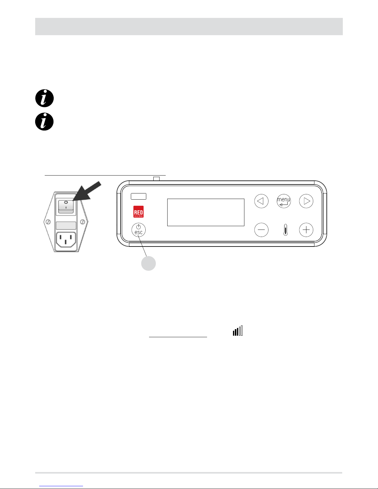
• Press the“menu”key.
• Use the arrow keys to scroll through and select“Settings”
• Press“menu”to conrm.
• Use the arrow keys to scroll through and select‘’Tones’’
• Press“menu”to conrm.
• With the + - keys, select“On/O”.
• Press“menu”to conrm and“esc”to exit.
e - External thermostat (see dedicated chapter)
f - Auto-Eco activation (see dedicated chapter)
To select the Auto-Eco function, proceed as follows:
• Press the“menu”key.
• Use the arrow keys to scroll through and select“Settings”
• Press“menu”to conrm.
• Scroll with the arrows and select“Auto-Eco”.
• Press“menu”to conrm.
• Use the + - keys to select“On”.
• Press“menu”to conrm and“esc”to exit.
g - Eco stop T (see dedicated chapter)
To select the Eco Stop T function, proceed as follows:
• Press the“menu”key.
• Use the arrow keys to scroll through and select“Settings”
• Press“menu”to conrm.
• Scroll with the arrows and select‘’T Eco o’’.
• Press“menu”to conrm.
• With the + - keys, insert the minutes (from 1 to 30’).
• Press“menu”to conrm and“esc”to exit.
AUTO ECO MODE (see above paragraph activation and switching o)
For activation of the“Auto Eco”mode and time settings, see paragraphs 8 f and 8 g respectively.
‘’ECO stop T’’ can be adjusted to ensure correct operation in the various environments in which the stove can be installed and to avoid
constant stopping and starting when the room temperature is subject to sudden change (drafts, poorly insulated rooms, etc.).
The ECO stop procedure is activated automatically when the power recall device is satised (room probe +1°C or external thermostat
with an open contact), the“ECO stopT”starts to decrease the time (factory default 5 minutes, which can be changed from the“Settings”
menu). During this phase, the panel alternates between displaying ON with a small ame and Crono (if active) - Eco active. The minutes
counting down to the Eco Stop are shown at the top of the display. The ame moves to P1 and remains there until the set“T Eco Stop”time
reaches zero, and if the conditions are still satised, turns o the boiler.The ECO stop count is cancelled if one of the devices recalls power.
When the boiler begins to turn o, the panel shows: O - Eco Active - ashing small ame.
When the stove turns o, OFF-ECO appears on the display with the ame symbol o.
The following conditions have to be met simultaneously for the ECO to restart:
• room probe -1°C or external thermostat with a closed contact (for at least 20”in order to prevent false recalls)
• 5 minutes have passed since shut-down.