Q. What have I got here?
A. The RR1EK2-0001 is a demonstra-
tion and evaluation kit that showcas-
es the capabilities and suggested
applications for Coto Technology’s
RedRock RR110 analog sensor and the
RR130 digital switch. The kit contains:
- The dual demonstration board
with the two RedRock devices
mounted at opposite ends
- An N52 Cylindrical magnet measuring 3/16” x 3/8”. Note that
the north pole is indicated for easy reference.
Q. How do I use the board?
A. There is a toggle switch located
near the bottom center of the board.
Toggling the switch to the left will
turn the board “on” with visual
feedback only. Toggling the switch
to the right will turn it “on” with both
audio and visual feedback active.
PLEASE NOTE: When the device is not
in use, this switch should be kept to
the center “o” position to conserve battery power.
When the included magnet is
brought near the RR110 (mounted on
the left side), the changing resistance
of the analog sensor will trigger a
variable response on the LED array
located in the center of the board.
Put simply, the stronger/closer the
magnetic eld presented to the
analog sensor, the more LEDs will be
activated on the LED array.
When a suciently strong magnetic
eld is presented to the RR130 on the
right side of the board, it will toggle a
yellow LED on.
Feel free to experiment with other
magnets you may be considering in
your application to vary the activa-
tion distances. You can also activate
the devices by bringing a south
magnetic pole near the two-pin side of the devices.
Q. What is the underlying technology in the RedRock RR110,
RR120, and RR130?
A. They operate on the principle of tunneling magnetoresistance
(TMR). It is a thin lm technology utilizing two ferromagnetic
layers, one with xed orientation and the other with variable
orientation. Between them is a very thin (typically nanometers)
insulating layer.
Together these layers form a magnetic sensor array. When the
sensor is exposed to an external magnetic eld, the variable
magnetic layer can “shift,” increasing the rate at which electrons
“tunnel” through the insulating layer.
This results in a change in resistance of the sensor array, sort of like
a magnetic potentiometer:
Q. What are the dierences between the analog and digital
sensors and switches?
A. The RR110 analog sensor oers a straightforward resistance
measurement, which varies depending on the strength of magnet-
ic eld the sensor is exposed to. The RR120 digital sensor takes it a
step further by integrating CMOS circuitry to establish a “high” and
“low” output. A strong enough eld will decrease resistance
enough to turn the RR120’s output to “low” whereas, when the
eld is removed, it will be “high.” The outputs from the RR110 and
RR120 are intended as inputs to a microprocessor. The RR130
digital switch adds an open-drain MOSFET at the output pin to
allow the device to act as a toggle switch to control a larger
voltage signal, potentially the control signal for a power relay
handling even higher loads.
Q. What are TMR’s advantages over other magnetic sensing
technologies?
A. Unlike Hall Eect, GMR, and AMR devices, TMR devices can
function with signicantly less power consumption and are highly
sensitive (yet resistant to damage from high power electromagnet-
ic elds). Furthermore, they oer an incredibly small package size
with the potential for even further size reductions.
Q. What are some of the other benets of TMR?
A. TMR oers the opportunity to customize the sensitivity
response to produce high or low hysteresis devices. The analog
sensor (RR110) oers a means of continuous sensing vs. a binary
“on” and “o” response, opening up some rather interesting
design opportunities. The devices are all RoHS compliant and
manufacturing friendly with tape & reel packaging for automated
pick and place.
Q. Is RedRock easy to “design in” to my application?
A. The answer is YES! The RR110 is a two pin resistor; all it takes is a
reference resistor to setup a voltage divider circuit that can easily
wire into an analog input on your preferred microprocessor for
easy analog readouts. The RR120 and RR130 are both three-pin
devices, easily wired into a digital input on a microprocessor or
toggling another circuit path, respectively.
Q. How are design engineers already using the RR110, RR120,
and RR130?
A. The magnetically operated sensors are being used as the critical
component in a "wakeup" circuit for a microprocessor-driven
device that spends signicant time in “standby” mode. They can
also act as a “mode changer” to switch between dierent operat-
ing modalities (e.g. hearing aid telecoil coupling mode). The digital
switch is ideal for power switching.
The analog sensor oers the capability for high precision multi-lev-
el uid sensing and proximity detection while both the digital
sensor and switch are ideal in small battery-powered medical
devices like insulin pumps, capsule endoscopes, and hearing aids.
Utility meters can also replace bare glass reed switches with TMR
sensors to increase reliability in rugged environments where the
glass reed switches might crack under stress.
Q. How is the board powered?
A. The board uses 3 AAA batteries, installed on the underside of
the board. If the Red LED is lit, this means the batteries should be
replaced.
Q. HELP! My board is acting strange.
A. The batteries are likely getting low. Installing new batteries
should resolve these issues.
Q. What if I have other questions?
A. Visit Coto Technology 24/7 online at cotorelay.com for a full
library of technical and applications information including product
datasheets, pad layouts, suggested soldering reow proles, a full
glossary of terms, and more. You can also submit questions
directly to our Applications engineers through a form on our
website or contact us via email at appsupport@cotorelay.com
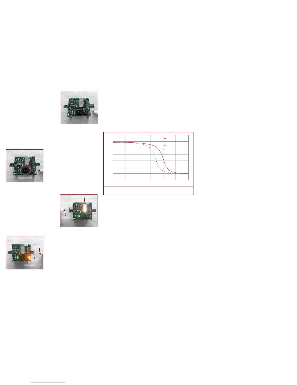
65
70
55
60
45
40
35
50
-150 -100 -50 0 50 150100
Sensor Resistance (kΩ)
Field Strength (G)
Magnet Approaching
Sensor
Magnet Receding
from Sensor
Copyright Coto Technology 2017. All rights reserved.
The magnetic sensitivity transfer curve illustrates the characteristic behavior of an analog
TMR sensor’s resistance change as the strength of an applied magnetic field changes.
Toggle Switch
RR110
MAGNET
RESPONSE LED LIGHTS
RR130
MAGNET
LED LIGHT