REDSHIFT MIRAGE User manual

Power Specs
The MIRAGE uses a standard 2.1mm 9V center negative DC supply. The pedal consumes approximately
200mA and should be used with a supply that can deliver at least 250mA.
Note: If the pedal enters firmware update/reset mode (cycling LEDs) when plugged in, this may
indicate that the pedal is not compatible with your supply. While the pedal is plugged in, try
pressing both footswitches and the multi-function button at the same time to trigger a reset.
The MIRAGE does not operate on batteries.
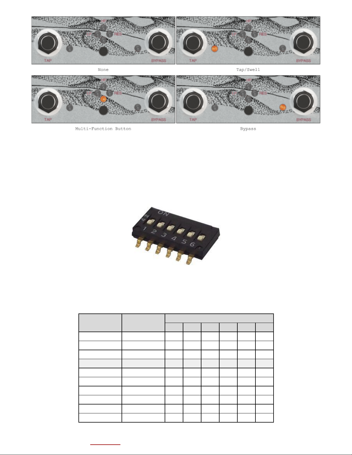
Bypass
The MIRAGE features true-bypass switching. In any mode, the footswitch on the right side of the
pedal functions as the bypass control. The LED next to this switch indicates the bypass state
(ON = engaged, OFF = bypassed).
Decay
The top-left knob, labelled ‘Decay’ controls the rate at which the signal decays after each
repeat. This knob’s function remains the same in any mode.
Tap
The footswitch on the left side of the pedal labelled ‘Tap’, controls the repeat time (or
tempo) of the delay in all modes. The number of taps required to set the tempo can be
configured in our pattern and configuration application. The default setting is 3 taps.
Swell
The footswitch on the left side of the pedal doubles as the ‘swell’ control. When this switch
is held down, the decay ‘swells’. When it is released, the swell subsides back to the decay
value specified by the Decay knob. The four LEDs in the middle of the pedal indicate the ‘swell
level’ while swell is active.
The rate at which swell increases and decays can be modified in the pattern and configuration
application. The maximum swell value can also be configured in software. When the maximum swell
value is 1.0, swell can be used to achieve repeat oscillation. When this value is greater than
1.0, swell can cause repeats to increase in volume. (Note: This can result in signal
clipping/distortion).
Volume and Mix
The two small black knobs located on the left side of the pedal control volume and mix. The
volume knob controls the output volume of the pedal. The mix knob is used to crossfade between
the dry and wet signals.
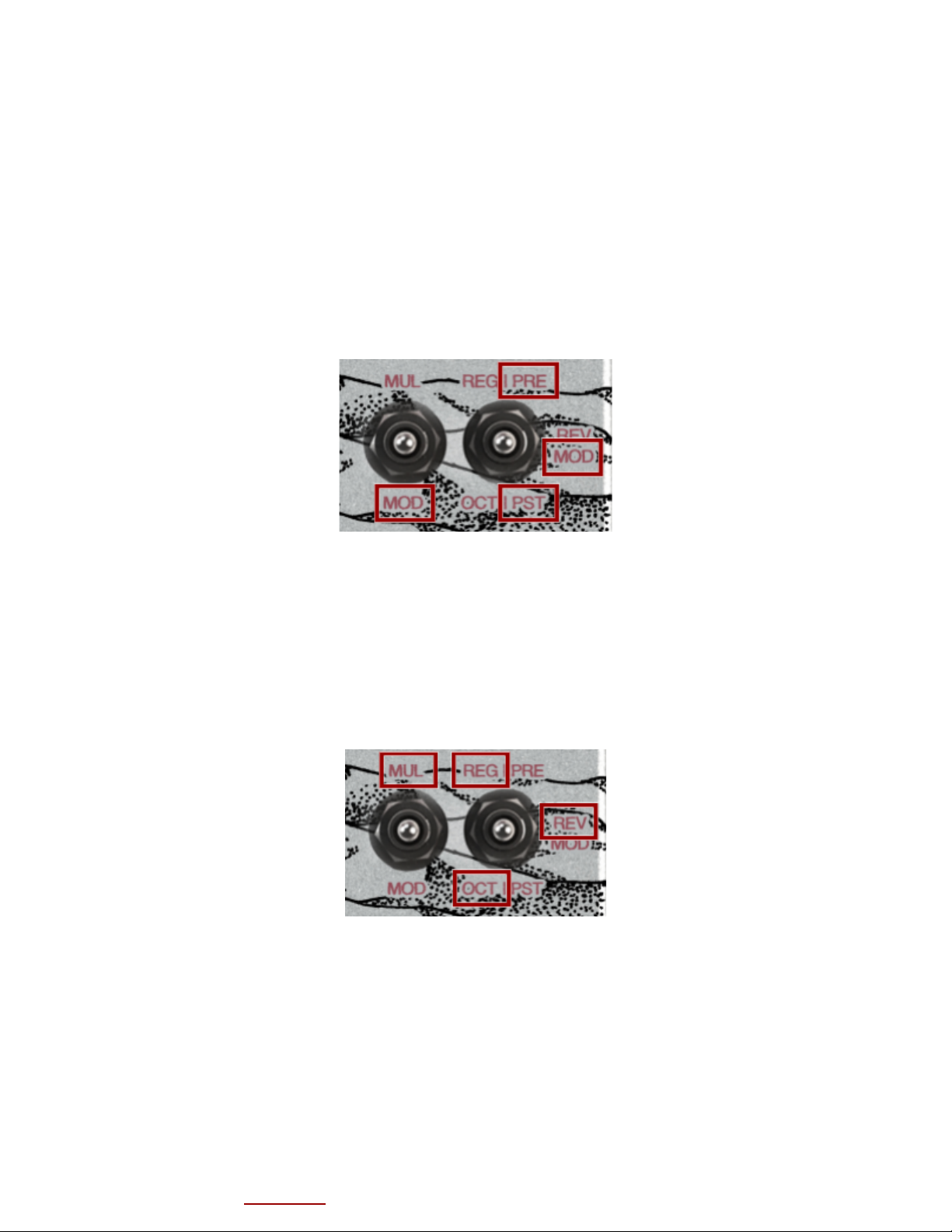
Modes
The MIRAGE features two main modes, selectable with the ‘mode switch’. Each mode features three
sub-modes, selectable with the ‘sub-mode switch’.
Modulation Mode
MIRAGE Manual V0.94 (Check our website for the latest version) 3

In modulation mode, the middle knob controls the modulation LFO depth and the right knob
controls the modulation LFO rate.
Modulation can be performed using volume (tremolo), a low-pass filter, a high-pass filter or a
resonant filter. The modulation method is selected using the multi-function button. The LEDs
indicate which method is in use. The illuminated LED will also indicate the LFO rate and depth.
The default modulation method can be set in the pattern and configuration application.
Setting the rate knob fully counter-clockwise enables non-modulated filter mode. In this mode,
the selected filter is not modulated by the LFO, but can be adjusted with the depth knob.
Modulation mode has three modulation sub-modes, allowing you to decide where the modulation
occurs; at signal input (PRE), before feedback (MOD) or after feedback (POST).
Multi Delay Mode
In multi delay mode, the middle knob selects the repeat pattern and the right knob controls
repeat ‘variance’.
Multi delay mode has three sub-modes or playback modes including regular, reverse and octave.
Whether or not a repeat is played in reverse in ‘reverse mode’ or an octave up in ‘octave mode’
depends on the pattern. This can be modified in the pattern editor.
The MIRAGE can store up to 15 custom patterns. When turning the pattern selection knob, the
selected pattern is indicated by the cluster of 4 LEDs.
Pattern 0 (pattern select knob fully counter-clockwise) is real-time pattern mode. In this
mode, repeats can be added by pressing the multi-function button. Repeats will be created at
the time of the press; pay attention to the tap tempo LED flashes to dial in your timing. Up to
six repeats can be added in this mode. To clear the repeats, simply switch to pattern 1 then
back to pattern 0.
MIRAGE Manual V0.94 (Check our website for the latest version) 4

In multi delay mode, the top right knob controls repeat Variance. The [VAR] knob adjusts the
amount of random variance
in the volume of each repeat. This give the repeat pattern a more
organic
feel. This knob also applies a low-pass filter which can smooth the occasional high
frequency ‘pops’ that can occur in the octave and reverse sub modes.
Expression/CV Input
The MIRAGE features a 3.5mm expression and CV combo input. Expression plugs must be TRS - Tip =
Wiper Output, Ring = Input, Sleeve = GND. CV plugs must be TS (not TRS) - Tip = Voltage,
Sleeve = GND. CV inputs must not exceed 5V. Improper inputs or plugs can result in damage to
the pedal.
To select the parameter to be controlled by expression/CV input, hold down the multi-function
button. While holding down this button, turn the top-right knob and use the top three LEDs in
the cluster of four LEDs to make a selection. Release the multi-function button to finalize
selection. The default selection can be set in the pattern and configuration application.
Note: When selecting, remember that each of the top 3 LEDs corresponds to the knob above it.
Note ii: When the multi-function button is released, both the switch and expression controls
are set based on the top-left and top-right knob positions respectively.
External Switch/CV Input
The MIRAGE features a 3.5mm external switch and CV combo input. Switch plugs must be TS (not
TRS). This input is compatible with normally open (N-O) type switches. For CV inputs, Tip =
Voltage, Sleeve = GND. CV inputs must not exceed 5V. Improper inputs or plugs can result in
damage to the pedal.
To select the parameter controlled by the external switch, use the same method as expression
selection with the top-left knob and bottom three LEDs (including the tap LED and bypass LED).
Note: When selecting, remember that each of the bottom 3 LEDs corresponds to the nearest
button/footswitch. The default selection can be set in the pattern and configuration
application.
MIRAGE Manual V0.94 (Check our website for the latest version) 5

Pre-gain/Attenuation - Internal DIP Switch
The input gain/attenuation of the MIRAGE can be configured using a small DIP switch (labelled
‘Input Level’) located on the pedal’s circuit board. To access this switch, the back of the
enclosure must be carefully removed. The DIP switch is quite delicate, use care when setting
it.
Many gain/attenuation settings are possible with this switch. The table below some of the
available settings. The default setting is 0dB (unity gain).
Gain (dB)
Gain (AV)
Switch Position
1
2
3
4
5
6
5.9
1.98
1
0
0
0
0
0
3.4
1.49
0
1
0
0
0
0
2.0
1.26
0
0
1
0
0
0
0.0
1
0
0
0
1
0
0
-1.4
0.85
1
1
0
0
0
0
-2.3
0.77
1
0
1
0
0
0
-2.6
0.74
0
0
0
0
1
0
-3.4
0.68
0
1
1
0
0
0
-4.5
0.6
0
1
0
1
0
0
-5.4
0.54
1
0
0
0
1
0
MIRAGE Manual V0.94 (Check our website for the latest version) 6

-6.0
0.5
0
0
0
0
0
1
-6.6
0.47
0
0
1
0
1
0
-7.4
0.43
0
0
0
1
1
0
-8.5
0.38
0
1
0
0
0
1
-9.6
0.33
0
1
0
1
1
0
-10.0
0.32
1
1
0
0
0
1
-10.5
0.3
0
0
0
0
1
1
-10.8
0.29
0
1
1
0
0
1
-11.7
0.26
1
0
0
0
1
1
-12.7
0.23
0
0
0
1
1
1
-13.7
0.21
1
0
0
1
1
1
-14.2
0.19
0
0
1
1
1
1
(1 = ON, 0 = OFF)
Loading Firmware
The RedShift Effects Firmware Loader software currently supports the following operating
systems:
●Windows 7 and higher
●Mac OS X 10.12 and higher
●64-bit Linux
Loading firmware onto the MIRAGE is simple:
1) Download and install the USB VCP drivers found here.
2) Download and install the RedShift Effects Firmware Loader from here.
3) Connect your 9V power adapter to the MIRAGE.
4) Connect the MIRAGE to your computer with the Mini-USB cable provided (Note: The tip of
the cable may protrude slightly when inserted, be careful not to force it).
5) Launch the RedShift Effects Firmware Loader software.
6) The application should display ‘Connected’ with a green circle beside it. A drag-and-drop
box should appear.
7) Drag in your .rse file and wait for the installation to complete.
8) Once complete, unplug your pedal and test out your new patterns and settings!
Note: If you experience an error during a firmware upload and the pedal will no longer connect
to the loader application, you can manually trigger firmware update mode. To do this,
disconnect the power cable. While holding down both footswitches, reconnect the power cable.
The LEDs should start to cycle, indicating that the pedal is in firmware update mode.
Creating Patterns and Configuring
Pattern creation and core configuration can be performed using the MIRAGE Tools web
application. MIRAGE patterns and configurations are stored in .rse files, which are created and
edited within the web application. As we improve our software, new firmware versions will also
become available through this application.
Need Help? Let us know.
MIRAGE Manual V0.94 (Check our website for the latest version) 7
Table of contents