Reece Franke FRG302S1 User manual

FRANKE
SPECIFICATIONS
Recommended use Domestic
Material Stainless Steel
Colour availability Stainless Steel
Weight 13.2kg
Dimensions 600 x 510 x 45mm
Voltage 220-240V / 50-60Hz
Burners 4
Control type A-TECH knobs solid steel
Gas type Natural and LPG
Semi-rapid burner 1750W 2
WOK burner 4000W (single inlet) 1
Auxillary burner 1000W 1
Flame failure Yes
Cast iron pan support Yes
Automatic ignition Yes
Power cord length 1850mm
CLEANING RECOMMENDATIONS
To see the complete FRANKE range go to
www.reece.com.au/bathrooms
DESIGNER GAS COOKTOP 60CM
We recommend the use of soapy water or approved cleaners.
This product should not be cleaned with abrasive materials.
Damage caused by any improper treatment is not covered by the product warranty. Refer to Warranty Conditions.
Dimensions are nominal measurements only.
Disclaimer: Products in this specication manual must by regulation be installed by licensed and registered trade people. The manufacturer/distributor
reserves the right to vary specications or delete models from their range without prior notication. Dimensions are nominal measurements only.
Dimensions and set-outs listed are correct at time of publication however the manufacturer/distributor takes no responsibility for printing errors.
Tech Page Version 1
600
560
510
480
Min 50
Min 600
45
page 1 of 7

INSTALLATION INSTRUCTIONS IMPORTANT WARNINGS
FRANKE
DESIGNER GAS COOKTOP 60CM
•Installation of the appliance into a kitchen worktop must be performed by an adequately qualified technician.
•Veneer or other finish of the piece of kitchen furniture into which the hob is to be built in should be treated with heat resistant glue
(100°C); otherwise, the worktop finish may be discolored or deformed.
• Ideally the appliance should be installed with plenty of space on either side. There may be a wall at the rear and a tall unit or wall at
one side. On the other side, however, no unit or divider should stand higher than the cooktop.
•Use of massive wood decoration plates or boards on the worktops behind the appliance is not permitted.
•The distance between the appliance edge and the adjacent tall kitchen furniture element should amount to no less than 250
mm.
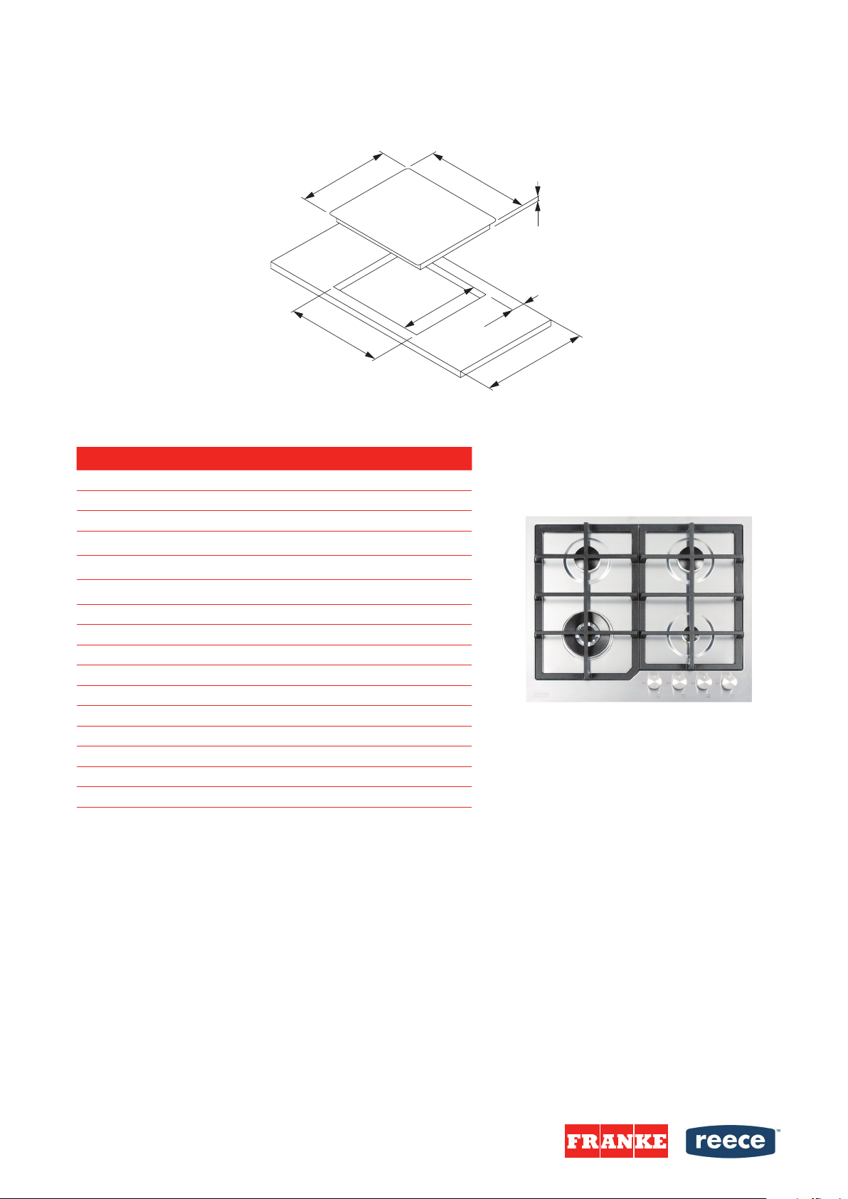
•All sizes and distances to be taken for the proper functioning of the appliance are shown in gures below.
•The kitchen furniture element underneath the hob should not be tted with a drawer. If the kitchen furniture element as a
horizontal partition wall, it should be installed no less than min 20mm from the lower surface of the appliance. The space
between the partition wall and the appliance must be empty; no objects should be placed into that gap.
•Hanging, or wall-mounted kitchen elements should be installed high enough not to interfere with the work process.
•A minimum safety distance must be maintained between the appliance and the cooker hood above it. See the cooker hood
manufacturer's operating and installation instructions for details. If the manufacturer's instructions are not available or, if
there are any ammable objects (e.g. utensil rails, wall units etc) above the appliance, a minimum safety distance of at least
800 mm must be maintained between them and the appliance below.
•Fit the wall units and cooker hood before tting the appliance to avoid damaging it.
•The front part must have an opening of no less than 5 mm.
•The appliance must not be installed over a fridge, fridge-freezer, freezer, dishwasher, washing machine, washer-dryer or
tumble dryer.
•Only ovens tted with a cooling fan may be installed underneath this appliance.
•Before installing an oven, the rear wall of the kitchen furniture element should be removed in the area of the appliance cut-
out. Furthermore, a gap of at least 5 mm should be left at the front side.
NOT ALLOWED NOT RECOMMENDED NOT RECOMMENDED RECOMMENDED
• Overhead clearances—(Measurement A) Range hoods and exhaust fans shall be installed in
accordance with the manufacturer’s relevant instructions. However, in no case shall the
clearance between the highest part of the hob of the gas cooking appliance and a range hood
be less than 600 mm or, for an overhead exhaust fan, 800 mm.
• Side clearances—(Measurement B & C) Where B, measured from the periphery of the
nearest burner to any vertical combustible surface, or vertical combustible surface covered
with toughened glass or sheet metal, is less than 250 mm, the surface shall be protected
to a height C of not less than 150 mm above the hob for the full dimension (width or depth) of
the cooking surface area. Where the gas cooking appliance is fitted with a "splashback“,
protection of the rear wall is not required.
page 2 of 7
Plumbers, please ensure a copy of the installation instructions
is left with the end user for future reference

INSTALLATION INSTRUCTIONS
Carefullyfit the provided insulating gasket around the outside edge of the hole made in
the top as shown below, pressing it down with your hands so that its entire surface fits
snugly (follow the dimensions shown).
After fastening the appliance to the top (see “Installation procedure”) carefully trim off the
excess of the gasket . The dimensions in the drawing below refer to the hole and to the
outside edge of the gasket.
FRG302S1 FRG604S1 FRG905S1
A
288 mm 600 mm 880 mm
B
510 mm 510 mm 510 mm
C
270 mm 560 mm 860 mm
D
480 mm 480 mm 480 mm
E
45 mm 45 mm 45 mm
F
3 mm 3 mm 3 mm
G
min. 50 mm m in. 50 mm min. 50 mm
H
min. 600 mm min. 600 mm min. 600 mm
Fit the insulating gasket
(for Stainless steel appliances)
Installation procedure
(with springs)
Installation procedure
(with xing brackets)
• Worktop must be absolutely horizontal.
• Seal the cut surfaces with a suitable sealant to avoid swelling caused by moisture. The
sealant must be heat resistant.
• Put the supplied springs in their places.
• Feed the mains connection cable down through the cut-out.
• Insert the appliance into the cut-out.
•Press the appliance firmly towards the worktop from above.
•Worktop must be absolutely horizontal.
•Seal the cut surfaces with a suitable sealant to avoid swelling caused by moisture. The
sealant must be heat resistant.
•Feed the mains connection cable down through the cut-out.
•Insert the appliance into the cut-out.
•Centre the appliance in the cut-out.
•Fix the appliance to the worktop by means of the brackets and accessories provided.
•Holes are provided in the bottom of the tray where you can attach the screws C that
hold the brackets B in place.
FRANKE
DESIGNER GAS COOKTOP 60CM
Plumbers, please ensure a copy of the installation instructions
is left with the end user for future reference
page 3 of 7

INSTALLATION INSTRUCTIONS
CONNECTING TO THE POWER MAINS
WIring diagram
•The appliance may ONLY be connected by an authorized qualied technician.
•Electric system protection should comply with all relevant regulations.
•The connection clips can be accessed when the connection clip covers are opened
removed.
•Before connecting the appliance, make sure the voltage indicated on the rating plate
is consistent with the voltage in your home network. Connection voltage should be
checked by a qualied technician using a corresponding measuring device!
•The rating plate with basic information is attached on the lower side of the appliance.
•In order to make a xed connection to the mains, insert an all-pole circuit breaker
between the appliance and the mains. This device shall have a contact separation in all
poles, providing full disconnection under overvoltage category III conditions.
•The current conducting and isolated parts must be protected from any possibility of
direct contact.
WARNING!
•Before any intervention, disconnect the appliance from the power mains. Connect the
appliance in compliance with the electric connections diagram supplied; make sure the
relevant network voltage is observed!
•The ground wire should be connected to the clip indicated by the earth symbol.
•The mains cable should be fed through the fastening clip which protects it from being
•accidentally pulled out.
•After connecting the appliance, turn on all cooking zones / heaters for approximately
three minutes to make sure they are operating correctly.
•Incorrect connection may destroy parts of the appliance, making the warranty void.
•Connection cable on the back of the appliance should be led in such way that it does
not touch the appliance back wall, as this part will get very hot during operation.
The following can be used for connection:
•H05RR-F , 3x1,5mm2
•H07RN-F , 3x1,5mm2
•H05RN-F , 3x1,5mm2
•H05V2V2-F , 3x1,5mm2
•H05VV-F , 3x1,5mm2
FRANKE
DESIGNER GAS COOKTOP 60CM
Plumbers, please ensure a copy of the installation instructions
is left with the end user for future reference
page 4 of 7

INSTALLATION INSTRUCTIONS
CONNECTING TO THE GAS SUPPLY
Connection
•Connection to the gas supply, or conversion from one type of gas to another, should
only be undertaken by an approved and registered gas installer in strict accordance with
local and national safety and building regulations.
•Check with your local gas supplier about the type of gas and its caloric value, and
compare this information with the type of gas quoted on the cooktop data plate.
•This appliance is not suitable for connection to a burning fumes exhaust system (i.e. a
chimney).
•WARNING: Special care must be taken to ensure adequate ventilation / aeration (a =
min. 100 cm2 ). The gas cooking appliance use may cause heat, humidity and products
of combustion in the room where is installed. Ensure that the kitchen is well ventilated
especially when the appliance is in use: keep open any natural ventilation holes or
install a mechanical ventilation device (mechanical extractor hood). Prolonged inten-
sive use of the appliance may call for additional ventilation, for example opening of a
window, or more effective ventilation, for example increasing the level of mechanical
ventilation where present.
There are two ways to carry out the connection to the main gas line:
A. The hotplate can be connected with rigid pipe as specied in AS/NZS5601.
B. The hotplate can be connected with a Flexible Hose, which complies with AS/NZS 1869 (Australian Certied),
10mm ID, class B or D, no more than 1.2m long and in accordance with AS/NZS5601. Ensure that the Hose does not
contact the hot surfaces of the hotplate, oven, dishwasher or other appliance that may be installed underneath or
next to the hotplate.
WARNING: Ensure that the hose assembly is restrained from accidental contact with the ue or ue outlet of an un-
derbench oven. The hose should not be subjected to abrasion, kinking or permanent deformation and should be able
to be inspected along its entire length. Unions compatible with the hose ttings must be used and connections tested
for gas leaks. The supply connection point shall be accessible with the appliance installed. The hose assembly shall
be suitable for connection to a xed consumer piping outlet located at a point 800mm to 850mm above the oor and
in a region outside the width of the appliance to a distance of 250mm.
•The flexible connection hose should be able to move freely, it should not come into
contact with the movable parts of the furniture or the bottom of the appliance.
• After connecting the appliance, check the joints for any leaks.
A ISO7-1 R1/2 connection plug
B Non-metal gasket with thickness of 2 mm
C Pipe adapter for liquid gas (depending on the model)
Only use pipes and seals in accordance with the Standards. These pipes must be installed so that, when fully extended, their
length does not exceed 2000 mm. For easier installation and to prevent gas leaks, attach the swivel coupling to the appliance
rst, and then to the gas mains pipe. Inverting this sequence may hamper the gas seal between the pipe and the appliance.
FRANKE
DESIGNER GAS COOKTOP 60CM
Plumbers, please ensure a copy of the installation instructions
is left with the end user for future reference
page 5 of 7

INSTALLATION INSTRUCTIONS
Before Leaving
•When installation is complete, check all connections for gas leaks with soap and water. DO NOT use a naked
ame for detecting leaks. Ignite all burners both individually and concurrently to ensure correct operation of gas
valves, burners and ignition. Turn gas taps to low ame position and observe stability of the ame for each burner
individually and concurrently. When satised with the hotplate, please instruct the user on the correct method of
operation. In case the appliance fails to operate correctly after all checks have been carried out, refer to the author-
ised service provider in your area.
•Ensure that the exible pipe cannot come into contact with any moving part of the cooktop (e.g. drawer) and that it is not in
a position where it could be damaged;
•Check the burners for correct operation. The ames must be clearly visible, and should be blue and green at the center. If
the ame is unstable, increase the minimum power.
•The appliance should not be removed from the worktop.
•Before converting, disconnect the appliance from the power mains and close the gas
supply valve.
•Remove the support grid and burner covers with respective crowns.
•Replace the existing nozzles for nominal thermal load with corresponding nozzles for
the new gas type and supplied provided (see Nozzle table). In double burners, adjust-
ment elements are accessible behind the main nozzle protective plate.
•After nishing this sequence, replace the old setting label with the new one provided for
the new injectors.
•The category with the related types of gas can be used are included in ʺConversion to a
different type of gasʺ table.
ADAPTATION TO A DIFFERENT
TYPE OF GAS
MINIMUM FLOW ADJUSTMENT
Instructions for Natural Gas
1. Light the burner and bring it to the minimum position.
2. Remove the control knobs, including the gaskets.
3. Turn the adjustment screw on the side of the tap rod until a regular minimum flame is
obtained:
·Anti-clockwise to increase the gas flow.
·Clockwise to reduce the gas flow.
4. Re-assemble the knob and verify burner flame stability (when quickly rotating the hand
from maximum to minimum position the flame must not shut off).
5. Repeat the operation on all gas taps.
Instructions for Universal LPG
Tighten the screw on the side of the tap, rod clockwise completely.
FRANKE
DESIGNER GAS COOKTOP 60CM
Plumbers, please ensure a copy of the installation instructions
is left with the end user for future reference
page 6 of 7

Plumbers, please ensure a copy of the installation instructions
is left with the end user for future reference
INSTALLATION INSTRUCTIONS
TECHNICAL INFORMATION
NOZZLE TABLE
FRANKE
DESIGNER GAS COOKTOP 60CM
page 7 of 7
This manual suits for next models
2
Table of contents
Popular Cooktop manuals by other brands

CDA
CDA HVG 93 Series Manual for installation, use and maintenance

Electrolux
Electrolux EW36IC60I - 36 in. Induction Cooktop Use and care guide

Frigidaire
Frigidaire FEC30S6ABC Factory parts catalog

Gaggenau
Gaggenau CX482611 installation instructions

GE
GE PP989 Owner's Manual & Installation Instructions

Kenmore
Kenmore ELITE 790.3322 Series Use & care guide