Reece KADO REHLXWH Quick start guide

KADO
SPECIFICATIONS
Recommended use Domestic, Hotel and Commercial
Fascia Material Aluminium & Glass
Colour availability White, Titanium
Weight 7.86kg
Heat 2 x 800 watt heat lamps
Light 18 watt LED panel
Air Movement 92 L/sec (330m3/H)*
Cutout Size 505 x 330mm
Rec Min Install Depth 220mm
CLEANING RECOMMENDATIONS
To see the complete KADO range go to
www.reece.com.au/bathrooms
LUX 3-IN-1 HEAT LIGHT EXHAUST
We recommend the use of soapy water or approved cleaners.
This product should not be cleaned with abrasive materials.
Damage caused by any improper treatment is not covered by the
product warranty. Refer to Warranty Conditions.
Dimensions are nominal measurements only.
Disclaimer: Products in this specication manual must by regulation be installed by licensed and registered trade people. The manufacturer/distributor
reserves the right to vary specications or delete models from their range without prior notication. Dimensions are nominal measurements only.
Dimensions and set-outs listed are correct at time of publication however the manufacturer/distributor takes no responsibility for printing errors.
Tech Page Version 1
360mm
530mm
148mm
195mm
10mm
505mm
330mm
*All airow data has been gathered in accordance
with International Industry Standards.
PART NO. REECE CODE
REHLXWH White 2053301
REHLXSS Titanium 2053302
page 1 of 4

KADO
LUX 3-IN-1 HEAT LIGHT EXHAUST UNIT
EXHAUST
Air Delivery 92 L/sec (330m3/H)*
Motor Power 65 watts
Noise Level 45dB(A)
Ball Bearing Yes
Duct Outlet Size 150mm
Draft Stopper Yes
LIGHT
Type LED Panel Light
Wattage 18 watts
Lumens 1521Lm
Colour (CCT) 4200K Natural White
HEAT
Type Instant Radiant Heat
Lamp Type 290mm Infrared Heat lamp
Lamp Wattage 2 x 800w
INSTALLATION
Cut Out Size 505 x 330mm
Fascia Size 530 x 360mm
Rec Min Install Depth 220mm
IP Rating IPX4 Splash Resistant
Installation Type Qualied Electrician Needed
PACKAGING
Packaging Size 640 x 390 x 275mm
Gross Weight 9.3kg
0
30
50
70
90
110
130
150
170
190
210
Static Pressure (pa)
m3/H 30 60 90 120 150 180 210 240 270 300
330
6m
4m
2m
REHLX
8m
10m
L/sec 8 17 25 33 42 50 58 67 75 83 92
Airflow
Duct Length
in relation to airflow
(Approx Only)
*All airow data has been gathered in accordance with International
Industry Standards.
TECHNICAL SPECIFICATIONS
INCLUDES
1 x Bathroom Unit
2 x 800 watt Heat lamps
1 x 18 watts LED Panel
1 x 4 Switch Wall Plate
1 x Cutout Template
AVAILABLE SPARE PARTS AND ACCESSORIES
Part Number Supplier Description
V150DKIT Ventair Ducting Kit with 1 x 150mm Grille and 6m Aluminium ducting.
VAD150 Ventair Ø150mm x 6m Aluminium Ducting.
V150PALG Ventair 150mm Premium Aluminium External Vent.
V31RFR Ventair Radio Frequency Remote Control to suit 3-in-1 Bathroom units.
VTROTIMER Ventair 1-25min Adjustable exhaust fan run-on timer.
VTMSENSOR Ventair Infrared motion sensor with 1-5m detection range and 1-20min
run-on timer.
VKLEDPNW Ventair 18 watt replacement LED Light panel.
VKHL800WH Ventair 800 watt replacement heat lamp.
page 2 of 4

INSTALLATION INSTRUCTIONS
KADO
LUX 3-IN-1 HEAT LIGHT EXHAUST UNIT
Please read these instructions carefully before installing and using the product. Keep the instructions handy for future
reference. Electrical wiring must only be done by a licensed electrician and a “Certicate of Compliance” must be issued on
completion of the installation.
LOCATION
The unit must be located and installed in accordance with AS/NZS 3000 and local building codes relating to damp situations.
The unit can be installed in any room that requires direct radiant heating and circulated airow such as bathrooms, ensuites,
laundries etc. The unit can be installed in at ceilings with a minimum height of 2.3 metres. At least 220mm height clearance in
the ceiling cavity is required to ensure sufcient ventilation for moisture to disperse. The unit must be installed at least 250mm
away from walls.
Ensure adequate inlets exist through windows, vents or under the door for airow.
Regulations concerning the discharge of air must be fullled.
POWER
AC220~240V, 50Hz electrical supply is required. The unit can be connected to a lighting or power circuit if loading permits.
All electrical work must be carried out in accordance with AS/NZS 3000 or latest edition thereof, and local building codes and
regulations. A four gang switch is included for all kinds of wiring combinations, e.g. One “HEAT” for one heat lamp and two
“HEAT” for two heat lamps. Ensure that the power supply is isolated before commencing installation.
MOUNTING
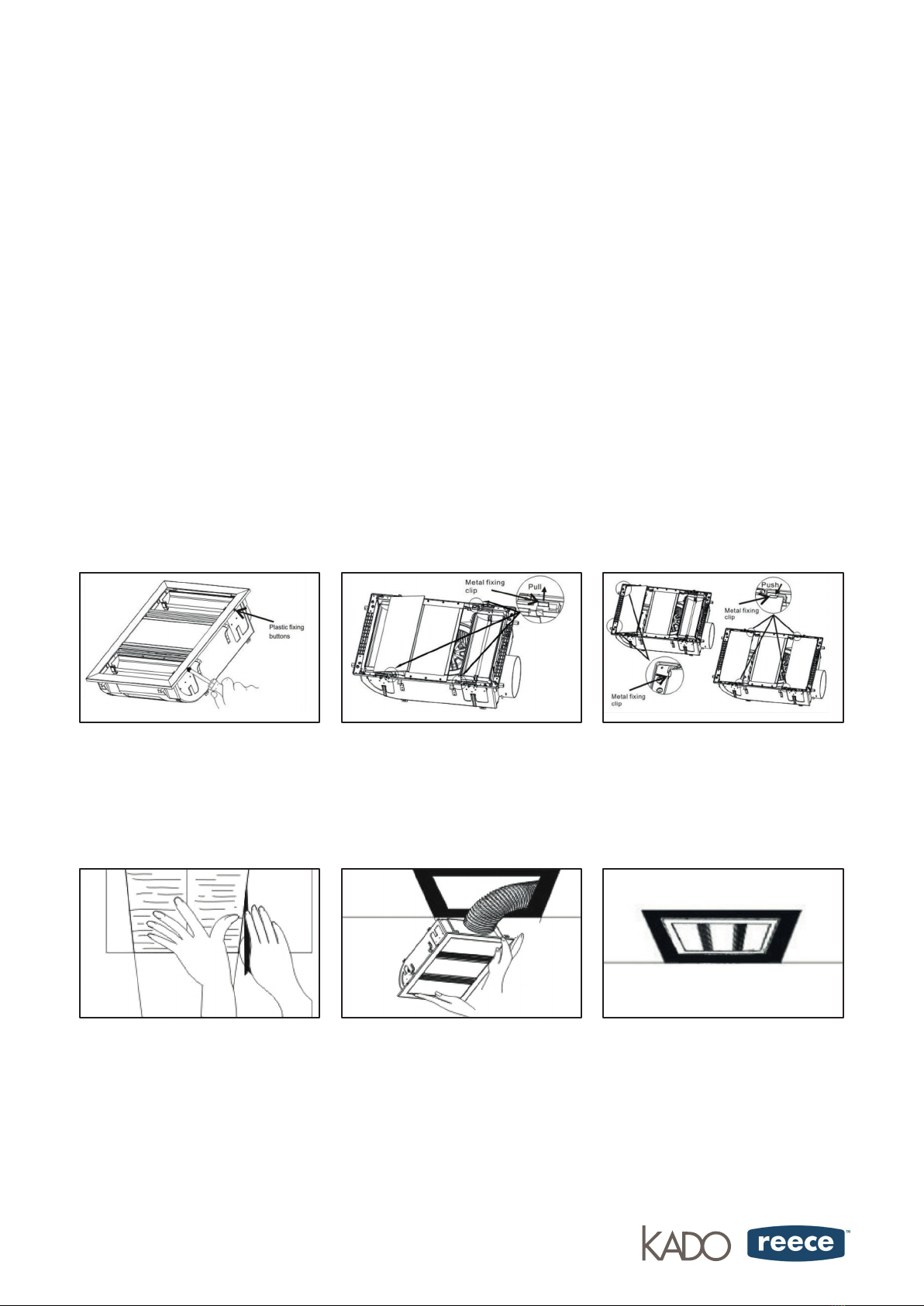
1. To remove Fascia, on one side of
the unit, press the plastic xing buttons
inwards and gently pry the fascia away
from the unit.
2. Bend the exible metal xing tabs
outward to allow the glass to be seated
in position.
3. Slide the glass into position against
the end tabs, then bend side xing tabs
back into position to ensure the glass is
xed securely.
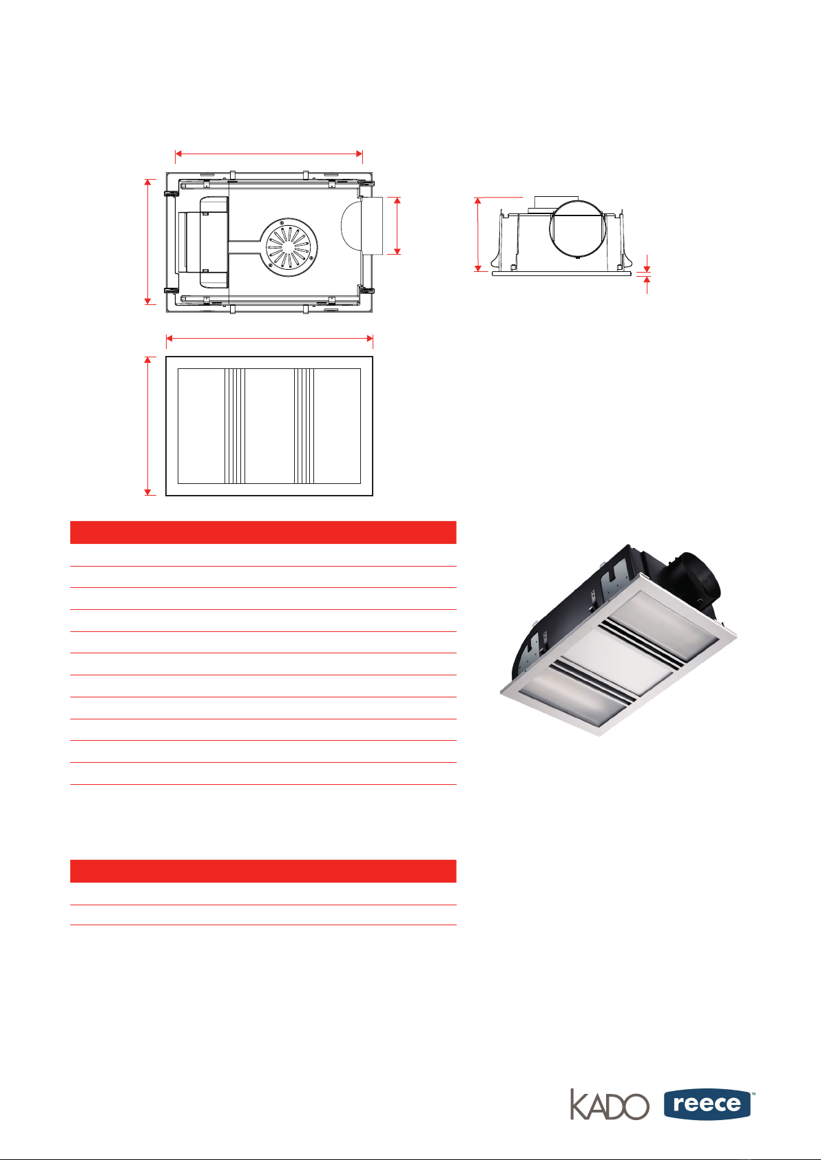
4. Use the supplied card as a template.
Place in the required location and
mark out the hole cutting size. The
hole size is 505mm x 330mm. Before
commencing cutting, ensure that the
area behind the intended location is
clear of all cables, pipes and joists.
Once clear, cut out the section along
the previously marked lines.
5. Remove terminal box cover on back
of unit and connect wiring as per wiring
diagram supplied. Connect Ducting
if required then insert unit into cutout
hole. Ensure the 4 metal xing springs
on sides have popped back into positon
on backside of Gyprock then tighten
4 x xing clamps at ends of units and
ensure unit is properly secured.
6. Replace fascia, locate one side
into position then gently press plastic
xing buttons on other side to help click
fascia into nal position.
page 3 of 4
Electricians, please ensure a copy of the installation instructions
is left with the end user for future reference.

INSTALLATION INSTRUCTIONS
KADO
LUX 3-IN-1 HEAT LIGHT EXHAUST UNIT
NOTICE: TO INSTALL THE HEAT LAMP, PULL UP THE LAMP SLIGHTLY FROM THE LAMP CLIP
AND THEN REMOVE THE QUICK CONNECTOR
ELECTRICAL WIRING
The unit must be located and installed in accordance with AS/NZS 3000 and local building codes relating to damp situations.
The unit can be installed in any room that requires direct radiant heating and circulated airow such as bathrooms, ensuite,
laundries etc. The unit can be installed in at ceilings with a minimum height of 2.3 metres. At least 220mm height clearance in
the ceiling cavity is required to ensure sufcient ventilation for moisture to disperse. The unit must be installed at least 250mm
away from walls.
Ensure adequate inlets exist through windows, vents or under the door for airow.
Regulations concerning the discharge of air must be fullled.
1. Connect the wiring to the four gang switch according to the below electrical diagram.
2. Remove the terminal cover on the heater unit and wire according to the lable adjacent to the terminal block. Make sure all
cables are securely connected and ret the terminal block.
3. Clean the fascia and lightings with a soft moist cloth. Turn on power and check the switch operation.
N
A
S/W LED
S/W FAN
S/W HEAT
S/W HEAT
N
L
S/W LED
S/W FAN
S/W HEAT
S/W HEAT
LED
M
C
•When installing the bathroom heater, please make sure
the person in the bathtub or shower area can’t touch the
electrical switches or other electrical controllers.
•This bathroom heater must not be installed below the
electrical outlet.
•This bathroom heater must not be installed near by any
curtains and other combustible materials.
•The appliance must under no circumstances be covered
with insulation material or similar material.
•Joists, beams and rafters shall not be cut or notched to
install the appliance.
•Lamps must be cool before cleaning. To clean bulbs and
surrounds, wipe with a cloth dampened with detergent or
liquid glass cleaner.
•This Appliance is not intended for use by persons
(including children) with reduced physical, sensory
or mental capabilities, or lack of experience and
knowledge, unless they have been given supervision or
instruction concerning use of the application be a person
responsible for their safety.
•Children should be supervised to ensure that they do not
play with the appliance.
•Appliance for indoor use only.
•Ensure that fan is switched off from supply mains before
removing the guard.
•National regulations concerning the discharge of air have
to be fullled.
•Means for disconnection must be incorporated in the xed
wiring in accordance with wiring rules.
CARE AND MAINTENANCE
WARNING: AN ALL-POLE DISCONNECTION MUST BE INCORPORATED INTO THE FIXED WIRING IN ACCORDANCE
WITH THE WIRING RULES AS OUTLINE IN CLAUSE 7.12.2 OF AS/NZS 60335-1 FOR
MEETING THE MINIMUM ELECTRICAL SAFETY OF THIS STANDARD.
page 4 of 4
Electricians, please ensure a copy of the installation
instructions is left with the end user for future reference
This manual suits for next models
3
Popular Ventilation Hood manuals by other brands

Venmar
Venmar ISPIRA IC700ES Series installation instructions

Fisher & Paykel
Fisher & Paykel 87641 installation instructions

DeDietrich
DeDietrich DHD1100X Guide to installation

Cuppone
Cuppone Tiepolo KTP 435 PRE-INSTALLATION AND INSTALLATION MANUAL

CONSTRUCTA
CONSTRUCTA CD96370 Instructions for installation and use

Mx Onda
Mx Onda MX-CDP2680 User and installation manual