Reef Pure RO Systems 6 Stage 400GPD Expert User manual

6 STAGE EXPERT RO/DI SYSTEM
USER MANUAL
Reef Pure RO Systems ©2018
Page of1 11
CONTENTS: PAGE:
CONTENTS 1
SAFETY INFORMATION 2
SYSTEM OPERATION 3
SYSTEM LAYOUT 4
INCLUDED PARTS 4
FILTER INSTALLATION INSTRUCTIONS 5
Connecting & Disconnecting Quick Connect Fittings 5
Reverse Osmosis Membrane Installation 5
Refillable Deionisation Cartridge Installation 6
SYSTEM INSTALLATION 7-8
TDS Meter Probe Placement 7
HM Digital"DM-1: Dual TDS Monitor - Usage Instructions 7
System Installation 8
FLOW DIAGRAM 9
MAINTENANCE 10
FAQ’s & TROUBLESHOOTING 10-11
Contact Information 11

6 STAGE EXPERT RO/DI SYSTEM
USER MANUAL
Reef Pure RO Systems ©2018
Page of2 11
WARNING: Reef Pure RO/DI Systems are designed for connection to your homes water supply. Failure to
adhere to the below points could lead to injury, flooding or system damage.
•Prior to operation check all connections are secure
•This system is only suitable for use indoors, in dry environments due to the electrical components
incorporated into the system. Use outdoors or in humid environments such as in close proximity to
aquarium sumps can cause permanent damage to the system and/or personal injury due to electric
shock.
•Check that all connections are secure prior to operation. Jaco style nut and collet tube connections
need to be checked and tightened using an adjustable wrench until the thread beneath the nut is
completely covered. Failure to properly check all connections could result in flooding and damage to
the RO/DI system.
•Inspect all connections, fittings and tubes for cracks, leaks and bulging hourly for the first 6 hours of
operation following installation. Inspect every 6 months thereafter and after any system adjustments,
replacing as necessary
•Always turn off the source water connection to the RO/DI system when not in use to prevent flooding
in the event of a leak
•Connecting this system directly to your aquarium or aquarium sump is not recommended. Doing so
may result in the flooding of your aquarium and harm to your aquarium’s inhabitants.
•This system is not designed to be connected directly to a float or similar valve within an aquarium
sump. These types of valves place excessive pressure on the system and its electronics by causing the
system to cycle rapidly between on an off cycles. This can cause permanent damage to the system
and the risk of electrical short.
•Always install the system in an area with appropriate drainage to avoid flooding in the event of a leak
•Do not leave the RO/DI system running and unattended for long periods of time
•Make sure all electrical connections are up and away from any potential leaks or spills
•Before changing filters or making any adjustments to the system, disconnect from mains power
•Make sure hands are dry before touching any electrical components
•In the event of a leak, turn off and disconnect power before making any adjustments
SAFETY INFORMATION

6 STAGE EXPERT RO/DI SYSTEM
USER MANUAL
Reef Pure RO Systems ©2018
Page of3 11
SYSTEM OPERATION
The Reef Pure RO Systems - 6 Stage Expert RO/DI System is a high-end RO/DI system designed to
produce up to 400 GPD (1514 Litres Per Day) or approximately 63 litres per hour of high quality, reef
grade, RO/DI water.
As this system includes a booster pump, excellent water pressure is assured, allowing the system to
perform efficiently and effectively.
Most RO/DI systems are designed to work with a 4:1 wastewater to production water ratio. This means
that for every 1 litre of RO/DI water produced, 4 litres will be diverted to the wastewater line. This water is
not suitable for use in your reef aquarium as it contains all of the rejected salts that your RO membrane
has filtered out.
However, this system halves the wastewater ratio produced by regular RO/DI systems by adding a
second RO membrane, doubling the amount of RO/DI water produced from the same amount of
waste water.
Never use hot water (water warmer than 45℃). Using warm or hot water will cause
permanent damage to your RO membrane, requiring the membrane to be replaced.
Do not use the system in direct sun as it will deplete deionisation resin cartridges and
can quickly heat the system causing permanent damage to the RO membrane.
Step-by-step tutorial videos can be found at https://reefpurero.com.au/user-manuals-
downloads/ or by searching for the Reef Pure RO System channel on YouTube.
!

6 STAGE EXPERT RO/DI SYSTEM
USER MANUAL
Reef Pure RO Systems ©2018
Page of4 11
SYSTEM LAYOUT
1. 2x 200GPD RO Membrane
2. 5 Micron Sediment Filter
3. Granular Activated Carbon
Filter
4. 5 Micron Carbon Block Filter
5. 2x Deionisation Resin
Cartridge
6. Pressure Gauge
7. Dual In-Line TDS Meter
1
2
3
4
5
6
7
INCLUDED PARTS
Housing Wrench
Feed Water
Connector
Colour Coded
Tubing
Wastewater Drain
Connector
2x 200GPD Thin Film
Composite Reverse
Osmosis Membrane
HM Digital DM-1: In-Line
Dual TDS Monitor
30V Sealed
Power Supply
1.8m Power Cord
Please ensure that all included parts have been received. In the unlikely event that any parts are
missing or have been damaged, please contact us immediately.

6 STAGE EXPERT RO/DI SYSTEM
USER MANUAL
Reef Pure RO Systems ©2018
Page of5 11
CONNECTING AND DISCONNECT QUICK CONNECT FITTINGS
Quick connect fittings can be found on the high pressure switch located on the top of the RO/DI system
main unit.
REVERSE OSMOSIS MEMBRANE INSTALLATION
1. Begin by disconnecting the 1/4” tube from the connector attached to the membrane housing
cap or pressure gauge, by completely unscrewing the collet securing the RO tube. There are
two RO membranes, one with a pressure gauge, and one with an elbow fitting.
2. Unscrew the cap from the membrane housing and insert the membrane firmly into the housing
ensuring that the end with the 2 rubber o-rings is inserted first. Twisting the membrane while
inserting can assist the connector to seat properly in the housing. Once fully inserted, no part of
the membrane will protrude from the membrane housing.
3. Once the membrane has been firmly seated, seal the membrane housing by replacing the cap
and tightening.
4. Reconnect the RO tubes ensuring they are connected back to their original connectors, making
sure to tighten the collets securely.
FILTER INSTALLATION INSTRUCTIONS
It is critical that the membrane is pushed in firmly and as far as it can possibly go. Not
doing so could allow high TDS water to bypass the membrane and make its way into
your product water, exhausting your DI resin prematurely.
Remove the tube by holding the round retention
ring tightly against the fitting then pulling the
tubing away from the fitting while twisting. The
tubing should slowly release from the fitting.
Push Connect fittings are connected by firmly
pushing one end of the tube into the fitting. It is
important to push the tube all the way into the
fitting for a complete seal.
Disconnecting Tube From Quick Connect Fittings:
Connecting Tube To Quick Connect Fittings:
The frequency at which you will need to replace your RO Membrane(s) will vary based
on the the quality of your home’s tap water and how much water you have
produced/filtered with the system. We recommend changing your RO Membrane
every 18 months to 2 years as a general rule.
"

6 STAGE EXPERT RO/DI SYSTEM
USER MANUAL
Reef Pure RO Systems ©2018
Page of6 11
REFILLABLE DEIONISATION CARTRIDGE INSTALLATION
1. Begin by removing the bottom cap from the cartridge and setting the cap & foam insert aside.
2. With the cartridge on a flat working surface, begin filling the cartridge with DI resin by slowly
shaking and tapping the bag, avoiding any spills.
3. Once you have filled the cartridge 3/4 of the way, stop and give the cartridge a few taps on a
bench top to make sure that the resin is compacted as tightly as possible.
4. Continue filling the cartridge. Once completed, tap it a few more times to ensure it is packed
tightly, making sure that you have left enough room for the foam insert and cap to replaced,
about 0.5-1cm.
5. Make sure the threads are clear of any resin beads before replacing the bottom cap. This will
make it easier to screw back on as well as ensure a water tight seal.
6. Using the palm of your hand, apply even pressure to the cap whilst screwing it back on.
7. When installing the DI cartridge into the housing, ensure that the cap is on the bottom with the
rubber seal facing up.
Packing the resin as tightly as possible is critically important to reduce the risk of
channelling during the production of water. Channeling will allow high TDS water to
bypass the the resin during water production.
A step-by-step tutorial video on packing a DI Resin Cartridge can be found at https://
reefpurero.com.au/user-manuals-downloads/ or by searching for the Reef Pure RO
System channel on YouTube.
!

6 STAGE EXPERT RO/DI SYSTEM
USER MANUAL
Reef Pure RO Systems ©2018
Page of7 11
TDS METER PROBE PLACEMENT
The HM Digital"DM-1: Dual TDS Monitor is an important tool in monitoring the performance of your RO/DI
system. It is also, being an electronic device, the only part of your RO/DI system which needs to be kept
dry. Make sure when mounting the TDS meter using the included adhesive strips that a location away
from any potential spills and direct sunlight is selected, ideally above your RO/DI system.
While it is up to you where the two probes are installed we highly recommend the below configuration:
IN Probe: Installed between the RO membrane and DI resin Stage(s). This will allow you to monitor the
TDS out of your RO membrane to ensure it is operating properly. The TDS reading out of the RO
membrane should be <10 ppm.
OUT Probe: Installed after the last DI resin stage. The reading after the DI resin should be 0 ppm at all
times. A reading higher than 0 indicates that the resin has been exhausted are requires replacing.
HM DIGITAL"DM-1: DUAL TDS MONITOR - USAGE INSTRUCTIONS
1. Press the “POWER” button to power on.
2. To display the TDS level of the RO filtered water, slide the switch to the IN side. This reading can be
used to monitor RO membrane performance. When this begins to rise above the usual reading, it is
likely time to replace your RO membrane.
3. To display the TDS level of the product (RO/DI) water, slide the switch to the OUT side. This reading
can be used to monitor DI resin performance. Any reading higher than 0 TDS means you need to
replace your DI resin.
4. The displayed TDS will always be most accurate after approximately 10 seconds of running.
5. Turn off the unit by pressing the “POWER” button. It will automatically shut off after 10 minutes.
It can also be useful to check your tap water TDS occasionally by moving one of the
probes temporarily. Typically though there is no need to continue monitoring the tap TDS
as the reading will seldom vary.
A full manufacturer instruction manual including more detailed installation notes is
included with every TDS meter.
"
SYSTEM INSTALLATION

6 STAGE EXPERT RO/DI SYSTEM
USER MANUAL
Reef Pure RO Systems ©2018
Page of8 11
SYSTEM INSTALLATION
1. Start by positioning your RO/DI system in the location it will be utilised in, close to an available water
source and drain connection, making sure to keep it in an indoor location, out of direct sun. Also
position the DI resin stage(s) close by for connection to the system.
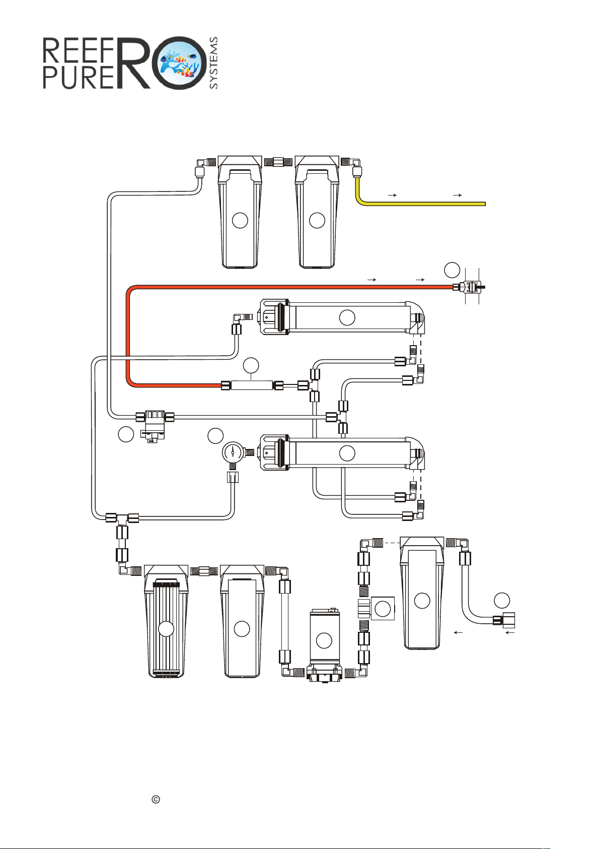
2. The thicker 3/8” white tube is the tap or source water line. Start by connecting one end of it to a tap
water source using the included feed water connector. The other end is then connected to your
systems Sediment filter inlet, located on the front above the sediment filter housing.
3. The red (or black) tube is the wastewater line. Connect one end of it to the 800ml flow restrictor
connector, identifiable by the small piece of red (or black) tube which comes pre-inserted (this is just
for your reference and can be discarded). The water this tube produces contains all of the
contaminants that your system has rejected and should be disposed of. We recommend directing it to
a drain utilising the Wastewater Drain Connector if necessary.
4. The yellow (or blue) tube is the production water line. This will be connected to the RO membrane
housing’s production water lines after the High Pressure Switch, identifiable by the small piece of yellow
tube which comes pre-inserted (this is just for your reference and can be discarded). Measure the tube
required to reach from this connector to the IN (left) side of the DI resin stages. Cut it and connect the
DI resin stage(s) to the main system. With the remaining piece of yellow tube, connect it to OUT
connector from the DI stages (right). This tube can then be directed to your RO/DI water storage
container.
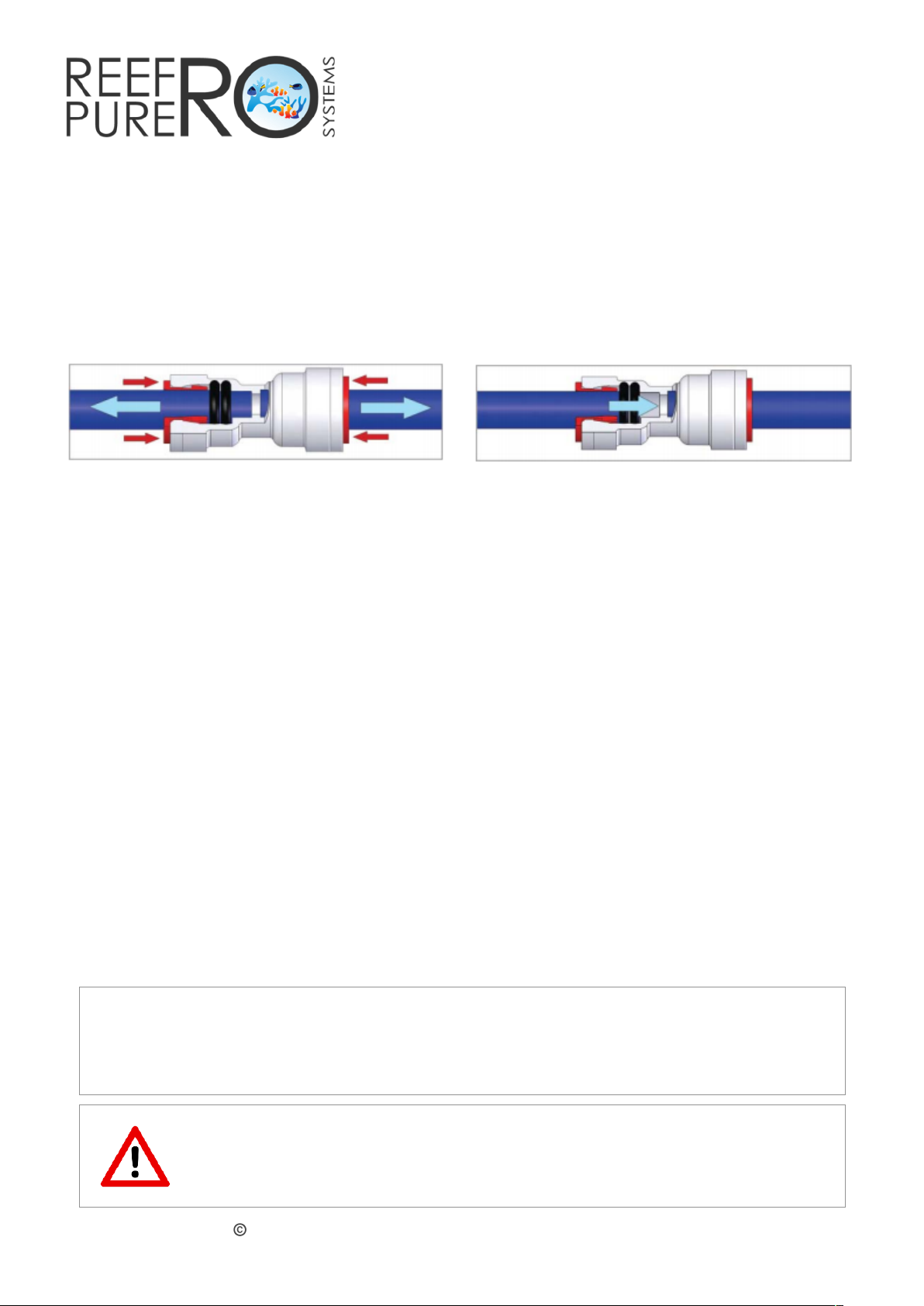
5. Connect the included power adapter to the available power connector on the rear of the system.
Sometimes the connect pins will not immediately align, if this happens wiggle the connector until the
pins align and the power connector clips together.
6. Connect the power cord to the power brick and plug in to an available power outlet.
7. Once all connections have been made, you can turn on the feed in tap. The built in solenoid valve will
prevent the flow of water until power is applied.
8. Switch on power to the system, which will now need to run for 30 minutes with all water produced
discarded in order to flush out any trapped air, preservatives used in manufacturing and fine particles
from carbon filters. This is a good time to check for any leaks and ensure that all connections are
Step 5 will need to be repeated each time carbon filters or membranes have been
replaced.
We strongly recommend the use of plastic containers made from HDPE for RO/DI water
storage as these are known to be reef aquarium safe. Look for the following symbol:

6 STAGE EXPERT RO/DI SYSTEM
USER MANUAL
Reef Pure RO Systems ©2018
Page of9 11
FLOW DIAGRAM
6 STAGE EXPERT
1. 5 Micron Sediment Filter
2. Granular Activated Carbon Filter
3. 5 Micron Carbon Block Filter
4. Reverse Osmosis Membrane
5. Rellable Deionisation Resin Cartridge
6. Pressure Gauge
1
3 2
5
6
9
8
5
WASTE WATER
PRODUCTION WATER
SOURCE WATER
7
4
4
10
11
12
7. Flow Restrictor
8. 1/2” BSP Source Water Connector
9. Waste Water Drain Connector
10. High Flow Booster Pump
11. High Pressure Switch
12. Solenoid Valve
FLOW DIAGRAM

6 STAGE EXPERT RO/DI SYSTEM
USER MANUAL
Reef Pure RO Systems ©2018
Page of10 11
FAQ’S & TROUBLESHOOTING
Why is the TDS coming out of my RO membrane really high when I first turn my system on?
This is perfectly normal and is called TDS creep. This occurs once the system has been turned off and
wastewater tries to equalise with pure water in the RO membrane chamber. Once the system has
been running for about 5 minutes, this should no longer be observed.
What TDS reading should I expect out of my RO membrane?
There are a number of environmental variances that will affect the TDS that you will achieve after your
RO membrane, before the DI resin stage. The largest factor is the beginning TDS of your tap water,
followed by the feed in water pressure. Pure-Pro RO membranes will achieve a 98% salt rejection rate
when provided with 50 psi in pressure for a single membrane or 65 psi for 2 membranes installed in
series. This means that if your starting tap water TDS is 200 ppm, then the TDS after your RO membrane
would be 4 ppm.
The DI resin on my system seems to become exhausted very quickly, why is this happening?
The rate at which your DI resin will become depleted will vary depending on 2 major factors. The most
significant factor is the TDS value of the water being fed into the DI resin stage. The higher the TDS
reading of the water coming out of your RO membrane, the more remaining contaminants your DI
resin will need to filter, thus exhausting it sooner. Secondly, high levels of dissolved carbon dioxide in
your home’s water supply will also exhaust DI resin much sooner.
What do I need to automate my Expert RO/DI system?
The Expert RO/DI system comes ready to automate out-of-the-box. When the system detects the
production water line is shut off, such as with an electronic solenoid valve or ball valve the system will
automatically turn off power and close the source water line with the built in solenoid valve.
Please Note: Float valves are not suitable for attachment to the production water line for the purposes
of automation as the reduced flow rates when the float valve has almost engaged will cause the
system to cycle on and off, damaging the electronic components. They should only be used as a
secondary redundancy.
MAINTENANCE
The frequency in which you will need to replace your pre-filters will vary dramatically based on the the
quality of your home’s tap water and how much water you have produced/filtered with the system.
We recommend changing your pre-filters every six months as a general rule.
From time-to-time, it may be necessary to remove or replace tubing into push-connect fittings. The
diagrams below illustrate how to do this.

6 STAGE EXPERT RO/DI SYSTEM
USER MANUAL
Reef Pure RO Systems ©2018
Page of11 11
FLOW DIAGRAM
6 STAGE EXPERT
1. 5 Micron Sediment Filter
2. Granular Activated Carbon Filter
3. 5 Micron Carbon Block Filter
4. Reverse Osmosis Membrane
6. Pressure Gauge
1
3 2
5
6
9
8
5
WASTE WATER
PRODUCTION WATER
SOURCE WATER
7
4
4
10
11
12
7. Flow Restrictor
8. 1/2” BSP Source Water Connector
9. Waste Water Drain Connector
10. High Flow Booster Pump
11. High Pressure Switch
12. Solenoid Valve
Need More Help? We are here for you! Please get in touch and let us know how we can
assist you…
1300 110 805
!contact@reefpurero.com.au
"
The system is switching off and on frequently during normal operation?
In some instances where source water pressure is already quite high, excessive pressure on the High
Pressure Switch can cause the RO/DI system to disengage prematurely. If this happens, the High
Pressure Switch needs to be moved, or re-plumbed so that it occurs after the DI Resin stages. After the
changes the production water line will run from the T-piece after the 2 membranes, to the DI stages, to
the High Pressure Switch then to your water storage vessel.
Alternately if not automating the system, the high pressure switch can be bypassed entirely.
Table of contents
Popular Water Filtration System manuals by other brands

AFRISO
AFRISO FloCo-Top-2 Series operating instructions

Crossfire
Crossfire CACTUS owner's manual

Pentair
Pentair EVERPURE MRS-100CC RO SYSTEM quick start guide

Bullard
Bullard 41 Series user manual

Steinbach
Steinbach Speed Clean Classic 250N ORIGINAL OWNER'S MANUAL

Outback Water
Outback Water Outback-Plus OB-25NF Installation and operating instruction manual

Raab
Raab KW ZUMIKRON Series Original operating instructions

MATALA
MATALA Biosteps10 Operation guidelines

Heal Force
Heal Force Smart-Mini Operation and service manual

Arcs
Arcs HYDROLOGIC HL-11670 manual

UV Dynamics
UV Dynamics UVSENSOR Installation and maintenance manual

Enwa
Enwa EnwaMatic EM BS 300 Operation and maintenance manual