Reeve TMA2Q User manual

Instruction Manual
Quadrature
Tower Mounted Amplifier TMA2Q
&
LNA Power Coupler LPC2Q
Copyright © 2016 W. Reeve
See last page for document revision information

TMA2Q & LPC2Q Instruction Manual
Table of Contents
Section Page
I. General ...........................................................................................................1
II. Installation ......................................................................................................3
III. Operation and Use.........................................................................................10
IV. Circuit Description .........................................................................................12
V. Maintenance .................................................................................................16
Appendix A Tower Mounted Amplifier Assembly..............................................................19
Document Information ..................................................................................20
Contact information:
Website: http://www.reeve.com/Solar/e-CALLISTO/e-callistoTMA2Q.htm
Email: [email protected]om
Please report errors and provide suggestions

TMA2Q/LPC2Q Quadrature Tower Mounted Amplifier Instruction Manual
Refer to last page for revision and copyright information, File: TMA2QInstructionManual.doc, Page 1
I. General
A. Application
The tower mounted amplifier system described here is designed to be used with CALLISTO instruments but
there is nothing in the design that prevents its use with other receivers within the frequency range 50 ... 500
MHz.
B. Description
The system includes two assemblies, the tower mounted amplifier assembly TMA2Q and LNA power coupler
assembly LPC2Q. The TMA2Q and LPC2Q are built, tested and sold as a pair. Refer to figure 1. The TMA2Q is
equipped with two low noise amplifier modules, one for each of two circuits, and associated bias-tees and
power supplies. The LPC2Q is equipped with complementary bias-tees and power supplies and a quadrature
coupler. The LPC2Q supplies power to the amplifier modules through the interconnecting transmission lines.
Bias-Tee
3.3 Vdc
Voltage Regulator
Bias-Tee
8.0 Vdc
Voltage Regulator
6.3~8.0 Vdc
3.3 Vdc
RF +
dc
RF RF
RF +
dc
dcdc
Tower-Mounted Amplifier Assembly
CALLISTO No. 1
RF In
Observatory
Power Supply
LNA Power Coupler Assembly
8.0 Vdc
Antenna A
CCW
Coaxial
Cable
TMA2Q LPC2Q
CALLISTO No. 2
LNA
In
LNA OutIn
Antenna B
CW
Coaxial
Cable
RF In
RF OUT + dc
CCW
RF IN + dc
N-S
RF IN
CCW
RF IN
CW RF OUT
N-S RHP
RF OUT
E-W LHP
Limiter
3.3 Vdc
Voltage Regulator
8.0 Vdc
Voltage Regulator
Bias-Tee
3.3 Vdc
Bias-Tee
RF +
dc
RF OUT + dc
CW
RF IN + dc
E-W
RF
Input
Isolated
+90°
Output
0°
Output
+90°
+90°
0°
0°
Quadrature
Coupler
Antenna
A and B are
cross-polarized
dc8.0 Vdc
RF +
dc
RF
6.3~8.0 Vdc dc
Out
12 Vdc
Figure 1 ~ System block diagram showing interconnections.
B. Basic Specifications
Parameter Value Remarks
Frequency range nominal 50...500 MHz Test limits, limited by quadrature coupler
Transmission gain nominal 17 ~ 13 dB Measured at test limits, varies with frequency, includes
coupler splitting losses
RF connectors N-female
Input voltage nominal 12 Vdc, range 11 ... 15 Vdc Power jack wired CENTER POSITIVE
Input current nominal 135 mA Maximum load of each LNA module is about 82 mA
Dimensions
TMA2Q: 9.5 in L x 7.4 in W x 5.3 in D
(241 mm L x 188 mm W x 135 mm D)
LPC2Q: 7.9 in. L x 4.3 in W x 3.2 in H
(200 mm L x 110 in W x 82 mm H)
Weight TMA2Q: 3.75 lb (1.7 kg)
LPC2Q: 2.2 lb (1.0 kg)

TMA2Q/LPC2Q Quadrature Tower Mounted Amplifier Instruction Manual
Refer to last page for revision and copyright information, File: TMA2QInstructionManual.doc, Page 2
If this equipment is to be used for calibrated measurements (such as calibrated measurements of solar flux or
any other weak signals) the temperature stability of the TMA2Q (and the associated receivers) must be taken
into account. The gain and noise of the TMA2Q (and receivers) vary slightly with ambient temperature. Refer to
the specifications and datasheets for the individual components. Datasheets for the modular components are
available from the manufacturer, Mini-Circuits, at http://www.minicircuits.com/, and Synergy Microwave, at
http://www.synergymwave.com/. For high measurement stability, the TMA2Q (and receivers) should be placed
in a temperature-controlled environment.

TMA2Q/LPC2Q Quadrature Tower Mounted Amplifier Instruction Manual
Refer to last page for revision and copyright information, File: TMA2QInstructionManual.doc, Page 3
II. Installation
A. Antenna Polarizations
Antenna installation is beyond the scope of this document and only polarizations are discussed here. The
TMA2Q/LPC2Q assemblies are designed to be used with a cross-polarized log periodic dipole array having a
frequency range of 50 to 500 MHz (for example, the Create Design CLP5130-1X). To reduce the effects of ground
reflections, the antenna should be oriented with the dipole elements at a 45° angle with respect to horizontal.
L
dc
Bias-Tee
C
RF OUT+dc
CCW
RF+dc RF OUT+dc
CW
RF IN
CW
RF
RF+dc
dc
Bias-Tee
C
TMA2Q Tower-Mounted Amplifier Assy.
ZFBT-282-
1.5A+
ZFBT-282-
1.5A+
SMA-MSMA-F
SMA-F
SMA-MSMA-F
SMA-F
SMA-F
RA
N-F
N-F
N-F
RF IN
CCW
L
Top
Bottom
SP-1
SP-1
Bottom
LP1
AD1 VL1
RF
LP2
AD1 VL2
+20 dB
AM1
OUT
IN
+20 dB
AM2
OUTIN
N-F
210
mm
SMA-F
RA
210
mm
Top
Bottom
N-FN-F
SMA-M
RA
SMA-M
150 mm
SMA-M
RA
SMA-M
150 mm
VOut
VOut
VIn
VIn
150 mm
150 mm
75 mm
75 mm
Earth
Top
Rear View
CW
Coaxial Cable
(Red)
Coaxial Cable
(Green)
To LPC2Q
CCW
Cross-Polarized
Log Periodic Dipole Array RG174
RG174
RG174
RG174
L
dc
Bias-Tee
C
RF+dc
N-S CCW
RF+dc
RF+dc
E-W CW
Input
+90°
+90°
0°
0°
Isolated
+90°
Output
0°
Output
RF
E-W ~ LHP
RF
RFRF+dc
dc
Bias-Tee
C
1
2
Power
E-W
N-S
LPC2Q Power Coupler Assy.
10u
50V 10n
50V
ZFBT-282-
1.5A+
ZFBT-282-
1.5A+
DQK-
50-500S
82u
0.8A
R
R
LED
LED
Notes:
1. For Jameco p/n 637183 (12 V LED), R = Internal
SMA-M SMA-F
SMA-F
SMA-M SMA-F
SMA-F
SMA-F
SMA-F
SMA-F
SMA-F
Quadrature
Coupler
On
On
N-F
N-F
N-F
N-F RF
N-S ~ RHP
2.1x
5.5mm
L
Top
Bottom
4 3
RG174
RG174
SMA-F
SMA-F SMA-M
SMA-M
SMA-M
SMA-M
SMA-M
SMA-M
SR260
Callisto No. 1
LHP
Callisto No. 2
RHP
Power Supply
11 … 15 Vdc
Power Supply
11 … 15 Vdc
Y
Cable
To
TMA2Q
CPS-1M
CPS-1M
Bottom
Top
Figure 2 ~ Block diagram showing antenna polarizations and corresponding connections to the TMA2Q (upper), LPC2Q and
receivers (lower). When viewed from the rear of the antenna toward the front, the CCW (Red reference) connector is

TMA2Q/LPC2Q Quadrature Tower Mounted Amplifier Instruction Manual
Refer to last page for revision and copyright information, File: TMA2QInstructionManual.doc, Page 4
pointed down and to the left. Similarly, the CW (Green reference) connector is pointed down and to the right. Also shown
for reference are the polarities of the most forward (shortest) dipole elements. The antenna configuration shown applies to
the CLP5130-1X antenna but the concepts apply to any cross-polarized antenna.
The two polarities should be marked with a color scheme for reference and this scheme should be carried
through the TMA2Q to the LPC2Q. In the supplied system, the colors Red and Green are used for reference,
where Red indicates a CCW rotation and Green indicates a CW rotation of the incoming radio waves as viewed
from the rear of the antenna; refer to figure 2.
If the reference connections shown in figures 1 and 2 are followed, the right-hand and left-hand circular
polarizations theoretically are output on the LPC2Q ports, marked respectively RHP and LHP on the end panel.
These connections and resulting polarizations require field verification. If they are found to be wrong, it is only
necessary to swap the connections to ports 3 and 4 of the quadrature coupler inside the LPC2Q.
B. Protection and Transmission Considerations and Pre-Installation Tests
Caution: Never work on the antenna system, coaxial cable systems, TMA2Q or LPC2Q if a lightning storm is in
the area. If a lightning storm is approaching, turn off the LPC2Q and disconnect the transmission lines and power
supply from the LPC2Q before it arrives. If lightning already is striking nearby do not touch any part of the
system including the PC that is used to collect data from the system.
Detailed transmission design and pre-installation tests are beyond the scope of this document. Only basic
recommendations are given here. To verify proper operation, it is suggested that all components used in the
installation be tested together before installation according to local practices. This includes the TMA2Q and
LPC2Q assemblies as well as the user-provided coaxial cables, power supplies and receivers. The quadrature
coupler in the LPC2Q depends on proper 50 ohm termination impedances on all ports. It is very important that
both transmission circuits are fully connected and terminated before any tests.
All coaxial cables and connectors should be high (commercial) quality, obtained from reputable suppliers and as
short as possible to minimize transmission losses. To minimize phase and attenuation differences in each circuit
section, the manufacturer and model of coaxial cables and connectors should be the same. To minimize phase
differences the cable section length differences should be as small as possible. Table 1 shows cable section
length differences that will produce 1° and 5° phase differences at various frequencies for typical 10 mm coaxial
cable. If possible, cable lengths and attenuation characteristics should be verified before installation with a
Cable and Antenna Tester (CAT) or Vector Network Analyzer (VNA). Both reflection (return loss or VSWR) and
transmission measurements should be included in these tests and compared with expected results.
Table 1 ~ Phase differences for LMR-400 coaxial cable (0.85 velocity factor)
Frequency
(MHz)
Length to produce
1° phase
(mm)
Length to produce
5° phase
(mm)
50 14.2 70.8
100 7.1 35.4
250 2.8 14.2
500 1.4 7.1

TMA2Q/LPC2Q Quadrature Tower Mounted Amplifier Instruction Manual
Refer to last page for revision and copyright information, File: TMA2QInstructionManual.doc, Page 5
Where the antenna is installed on a rotator, ultra-flexible coaxial cables, typically 6 mm diameter, should be
used to connect the antenna to the TMA2Q. The cables from the TMA2Q to the LPC2Q should be 10 mm
diameter to minimize transmission losses. The cables from the LPC2Q to the receivers can be 6 mm diameter if
less than a few meters long.
In addition to the major components in the TMA2Q/LPC2Q there are other components or conditions that
introduce phase variations and circuit losses including mismatch and insertion losses. All external RF connections
use type N connectors, which if good quality and properly installed, do not introduce appreciable transmission
losses or phase variations below 500 MHz. Mismatch losses are not discussed here. Typical measured insertion
losses for the TMA2Q and LPC2Q assemblies are shown in figure 3.

TMA2Q/LPC2Q Quadrature Tower Mounted Amplifier Instruction Manual
Refer to last page for revision and copyright information, File: TMA2QInstructionManual.doc, Page 6
Figure 3 ~ Typical transmission loss (s21) for circuit “CW” and circuit “CCW” from 10 to 1000 MHz. See note.
Note to figure 3: Transmission losses shown above are typical and include the internal cables. Expect variations due to
component tolerances. Measurements were made using a vector network analyzer under the following conditions after 30
minute warm-up period at room temperature:
☼Coaxial cable between VNA port 1 and TMA2Q RF Input: LMR-400UF, 1.22 m long
☼Coaxial cable between LPC2Q RF Inputs/dc and TMA2Q RF Outputs/dc: LMR-400UF, 0.46 m long
☼Coaxial cable between LPC2Q RF Output and VNA port 2: LMR-400UF, 1.22 m long
☼Unused circuit ports terminated with 50 ohm terminations
☼VNA output level –30 dBm and frequency range 10 to 1000 MHz
☼Markers: 10, 50, 100, 500 and 1000 MHz
At lower frequencies, the system gain is nominally the same as indicated in the amplifier datasheet less splitting
losses through the quadrature coupler of approximately 3.5 to 4.5 dB. At higher frequencies there are additional
implementation losses due to the interconnecting cables and the two bias-tees in each circuit. Where longer
interconnecting cables are used, the gain will be less than shown in the plot and will roll off more at higher
frequencies.
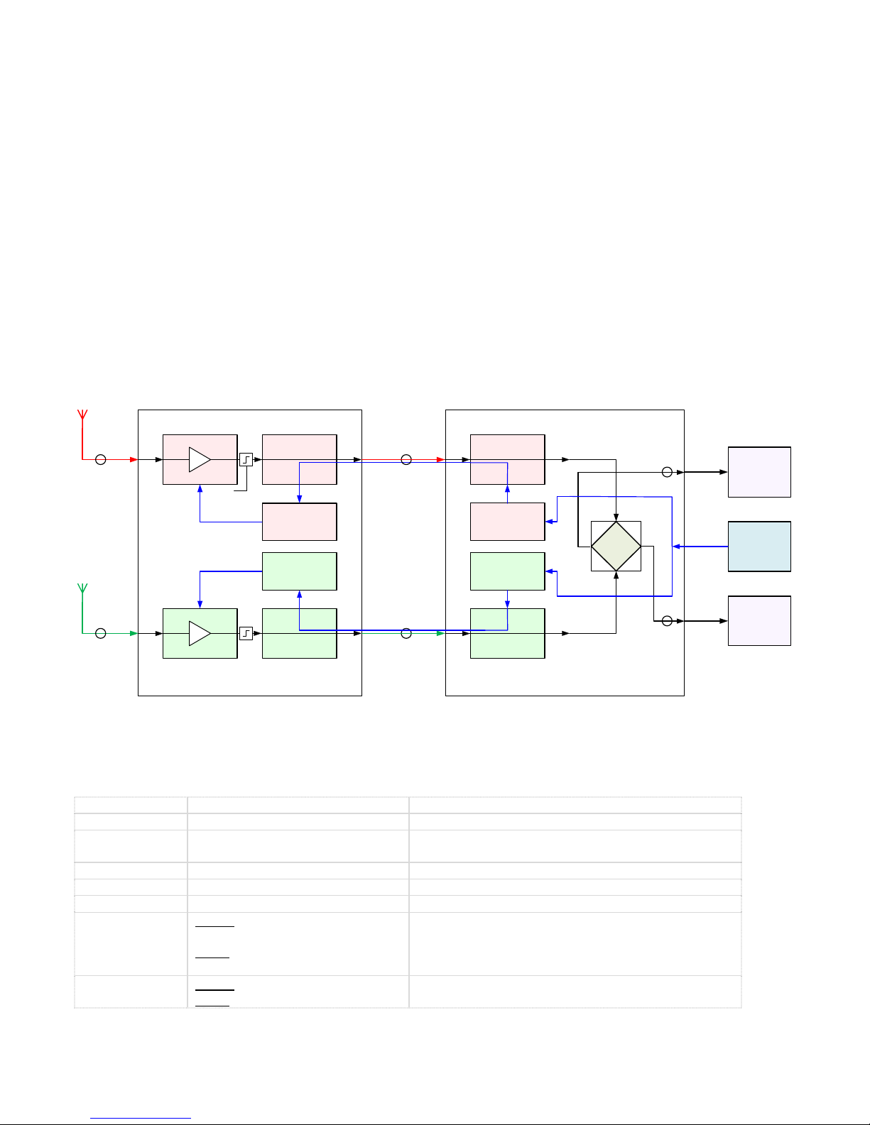
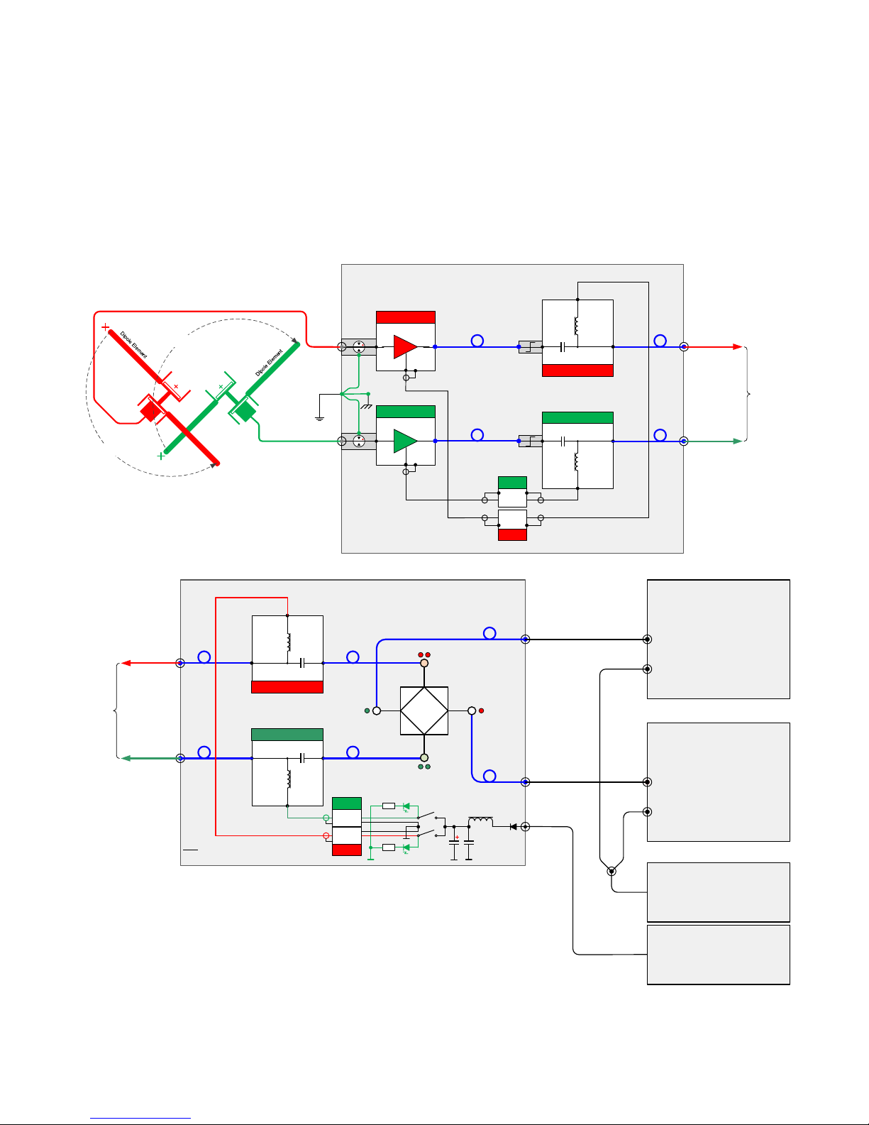
Caution: Do not attempt to use the TMA2Q/LPC2Q without all RF connections. These include 1) two circuit
connections between a cross-polarized antenna covering 50...500 MHz and the TMA2Q RF IN, 2) two circuit
connections between the TMA2Q RF OUT and LPC2Q RF IN, and 3) two circuit connections between the LPC2Q
RF OUT and two receivers RF IN.
C. TMA2Q Tower Mounted Amplifier Installation
Caution: The TMA2Q may be partially disassembled for shipment. If so, a paper warning flag will be inserted in
the TMA2Q cover. In this case, the TMA2Q will require final assembly before testing and installation. See
Appendix A. Whether or not any final assembly is required, the TMA2Q cover should be removed and the
internal area inspected for shipping damage or loose cables. Prior to shipping all connections are properly
torqued; DO NOT re-torque unless the connectors are found to be loose.
Caution: Connect transmission lines at the TMA2Q before connecting them to the LPC2Q, and before connecting
at the TMA2Q momentarily short the center contact of the cable connector to the shell to dissipate any static
build-up in the cable. Never apply a short to the cable if it is connected to the LPC2Q and the LPC2Q power is
turned on.
Caution: To minimize transient voltages on active components in the TMA2Q and LPC2Q assemblies and to
prevent accidental opening of the overcurrent protection circuits in the LPC2Q, DO NOT apply power to the
LPC2Q until all transmission line connections have been made between the TMA2Q and LPC2Q.
Caution: Only the LPC2Q is equipped with reverse polarity protection for the two internal power supplies; the
TMA2Q power supplies are not equipped with reverse polarity protection. Do not connect anything to the
TMA2Q RF output + dc port unless its polarity and voltage are known to be correct. The TMA2Q maximum input
voltage is 8.0 Vdc with the center conductor of the coaxial power connector positive polarity with respect to the
connector shell.

TMA2Q/LPC2Q Quadrature Tower Mounted Amplifier Instruction Manual
Refer to last page for revision and copyright information, File: TMA2QInstructionManual.doc, Page 7
Caution: Observe anti-static discharge practices at all times.
The TMA2Q assembly should be located as close as possible to the antenna system. It may be desirable to install
a Sun shade to reduce TMA2Q internal temperature variations in hot and sunny climates.
The TMA2Q enclosure has built-in mounting brackets with dimensions shown in figure 4. The brackets are
typically fastened to two channel struts, which in-turn are fastened to a mast or tower leg. All fasteners and
mounting hardware exposed to the weather must be suitable for the environment; generally galvanized steel or
stainless steel materials are used.
The TMA2Q has provisions for bonding the metallic components and internal lightning arrestors to an earth
electrode system (terminal is marked EARTH). The grounding/bonding stud is stainless steel, 10-32, and will
accept a copper terminal lug. The bond to the tower should be No. 6 AWG copper and be as short and straight
as possible and be installed according to local practice.
Mount the TMA2Q with the RF connectors and weep-hole oriented downward. All RF connectors on the outside
of the enclosure are female type N connectors, and the corresponding coaxial cables must have male Type N
connectors. Type N connectors should be made up finger-tight; never use a wrench or pliers on the type N
connectors.
The TMA2Q is equipped with two LNA modules and requires two independent RF transmission circuits, one
labeled “CCW” and the other labeled “CW” (figure 5). Connections
always are made to both circuits. It is suggested that before the
coaxial cables are installed they be marked with colored tape or
colored heat-shrink tubing. This will help reduce the possibility of
incorrect connections to the circuits during and after initial
installation. On the system drawings, circuit “CCW” is color coded red
and circuit “CW” is color coded green.
Figure 4 (left) ~ Tower Mounted Amplifier mounting dimensions in inches
D. LPC2Q LNA Power Coupler Installation
Caution: Connect transmission lines at the TMA2Q before connecting
to the LPC2Q, and before connecting at the LPC2Q momentarily short
the center contact of the cable connector to the shell to dissipate any
static build-up in the cable. Never apply a short to the RF In + dc port
of the LPC2Q.
Caution: To minimize transient voltage damage to active components
in the TMA2Q and LPC2Q assemblies and to prevent accidental
opening of the overcurrent protection circuits in the LPC2Q, DO NOT
apply power to the LPC2Q until all transmission line connections have
been made between the TMA2Q and LPC2Q.
0.375in.
4.00in.
8.75in. min, 8.875in. max
0.3125in.
Enclosure Mounting Dimensions
NOT TO SCALE

TMA2Q/LPC2Q Quadrature Tower Mounted Amplifier Instruction Manual
Refer to last page for revision and copyright information, File: TMA2QInstructionManual.doc, Page 8
Caution: The LPC2Q is equipped with reverse polarity input protection on the internal power supplies; however,
do not connect anything to the dc power input unless its polarity and voltage are known to be correct.
Caution: Observe anti-static discharge practices at all times.
The LPC2Q assembly does not have mounting brackets, and it should not be installed where exposed to the
weather or direct sunlight. The LPC2Q should be located at a convenient indoor location close to its power
source to minimize voltage drop. The minimum input voltage to the LPC2Q is 11.0 Vdc. It is not necessary to
install the LPC2Q near the receiver but care should be taken to minimize transmission losses. As with the
TMA2Q, all RF connections on the LPC2Q are female type N and the corresponding cables require male type N
connectors (figure 6). Connectors should be finger-tight; never use a wrench or pliers on the type N connectors.
The dc power connection to the LPC2Q is through a 2.1 x 5.5 mm coaxial power jack and plug (center positive). A
matching plug is supplied with the TMA2Q/LPC2Q. The user must solder insulated conductors to the power plug
and provide power supply connections. The power plug can accommodate 18 AWG (1 mm diameter) or smaller
insulated stranded conductors.
IMPORTANT: The power plug must be wired with center positive. Double-check the polarity before inserting
the plug; see caution above. The allowable input voltage range is 11 to 15 Vdc. The dc power source should be
filtered and capable of supplying 300 mA.
If a power supply was purchased with the TMA2Q/LPC2Q, it includes a proper power plug.
Figure 5 ~ Bottom view of TMA2Q showing connections

TMA2Q/LPC2Q Quadrature Tower Mounted Amplifier Instruction Manual
Refer to last page for revision and copyright information, File: TMA2QInstructionManual.doc, Page 9
Power Coupler
Anchorage, Alaska USA
Model:
S/N:
Date:
N-S Power E-W
+15 Vdc
RF IN + dc
E-W
RF IN + dc
N-S
RF OUT
E-W ~ LHP
RF OUT
N-S ~ RHP
Figure 6 ~ LPC2Q panel layouts showing connections. Note: The end panels used on the LPC2Q are also
used with the LWA power coupler model LWAPC. The E-W and N-S nomenclature silkscreened on the
panels applies only to the LWAPC and can be ignored.
E. Post-Installation Tests
It is recommended that a set of transmission and noise measurements be made immediately after installation.
These measurements will provide a baseline for comparison with maintenance measurements made later. A
complete set of measurements are included with the TMA2Q/LPC2Q but these are made with short
interconnecting cables.
Do not skip this step: After all connections have been made and post-installation tests have been completed,
seal all coaxial connections with rubber mastic tape or a coaxial connector sealing product.

TMA2Q/LPC2Q Quadrature Tower Mounted Amplifier Instruction Manual
Refer to last page for revision and copyright information, File: TMA2QInstructionManual.doc, Page 10
III. Operation
A. TMA2Q Tower Mounted Amplifier
The TMA2Q has no operating controls. Power for the TMA2Q is supplied by the LPC2Q through the “CCW” and
“CW” circuit coaxial cables. When power is applied to the TMA2Q through the LPC2Q, and the coaxial cables are
connected, the green LED on the TMA2Q power supplies will illuminate. The LEDs are not visible when the cover
is on the TMA2Q during normal operation. Remove the cover to view the LEDs during circuit verification and
troubleshooting.
B. LPC2Q LNA Power Coupler
The LPC2Q has two internal power supplies, each equipped with a resettable PTC fuse. These power supplies are
controlled by the two On/Off switches located on one end panel just above the coaxial dc power jack. The
internal power supplies provide power to the TMA2Q power supplies through bias-tees and the interconnecting
coaxial cables.
To operate the TMA2Q/LPC2Q after all RF and power cable connections have been made as described in the
Installation section, move the power switches to the On position. A green light emitting diode (LED), located
immediately above each On/Off switch on the LPC2Q, illuminates when power is turned on. If the LEDs fail to
illuminate, check the power supply, power cable and connector. The end panel LEDs indicate only that power is
applied to the LPC2Q power input circuits and do not indicate that power is being supplied to the TMA2Q. See
above.
C. Callisto Setup
There are two areas of the Callisto setup that need to be tailored for use with the tower-mounted amplifier
system: 1) Callisto gain setting; and 2) frequency range. Only the settings are provided below; refer to the
Callisto Software Setup Guide for specific procedures {Callisto}.
Gain: The Callisto gain is specified in the Callisto configuration file callisto.cfg by adjusting the PWM value in
parameter [agclevel]. The range is 50 to 255 with 50 corresponding to minimum gain and 255 corresponding
to maximum gain. When used with the TMA2Q/LPC2Q, the gain value typically will be set around 100 to 120.
Experimentation will be needed to find the best value, which may be outside this range. Higher gain settings
decrease the Callisto instrument noise figure but increase the possibility of receiver front-end overload.
Similarly, lower gain settings increase the Callisto noise figure but decrease the possibility of overload.
Frequency: The Callisto frequency range is specified by two settings. First, the frequency range is specified in the
frequency file frqxxxxx.cfg, where xxxxx is an arbitrary user assigned numeric value. Typically, the range is 50 to
500 MHz in 200 channels with a sweep rate of 4 sweeps/second. This provides approximately 2.3 MHz
resolution. Higher resolution can be attained by using more channels at a slower sweep rate (the product of the
number of channels and sweep rate should not exceed 800). However, it may be necessary to block the FM
broadcast band, television channels or other frequencies from the frequency file due to radio frequency
interference.

TMA2Q/LPC2Q Quadrature Tower Mounted Amplifier Instruction Manual
Refer to last page for revision and copyright information, File: TMA2QInstructionManual.doc, Page 11
The frequency file usually is setup using the Frequency Genie software tool and then edited if necessary for the
specific installation. After the frequency file has been generated and placed in the proper folder, it is referenced
in callisto.cfg by assigning the frequency file name to the parameter [frqfile].
An example of callisto.cfg parameters is shown below with // indicating the affected parameters. Refer to the
Callisto Software Setup Guide for parameter definitions and other requirements for the configuration file.
[rxcomport]=COM1
[observatory]=12
[instrument]=MY_INST
[titlecomment]=MY_RO
[origin]=NA
[longitude]=W,100.0
[latitude]=N,50.0
[height]=0.0
[clocksource]=1
[filetime]=900
[frqfile]=frq50500.cfg // user prepared frequency file
[focuscode]=59
[mmode]=3
[fitsenable]=1
[datapath]=c:\Callisto\Data\
[logpath]=c:\Callisto\Log\
[lcpath]=c:\Callisto\Lc\
[ovspath]=c:\Callisto\OVS\
[chargepump]=1
[agclevel]=120 // PWM level for gain, range 50...255, default 120
[detector_sens]=25.4
[db_scale]=5
[autostart]=0
[priority]=2
An example frequency file with nominal 50...500 MHz range is shown below, but it shows only the first ten and
last five frequencies in the list of 200 channels. Refer to the Callisto Software Setup Guide for parameter
definitions and other requirements for the frequency file.
[target]=CALLISTO
[on_line_testpoint_number]=100
[number_of_measurements_per_sweep]=200
[number_of_sweeps_per_second]=4
[external_lo]=0.000000
[0001]=0050.000,0
[0002]=0050.000,0
[0003]=0050.000,0
[0004]=0050.000,0
[0005]=0050.000,0
[0006]=0050.000,0
[0007]=0050.000,0
[0008]=0050.000,0
[0009]=0052.313,0
[0010]=0054.688,0
...
...
[0196]=0496.438,0
[0197]=0498.813,0
[0198]=0501.188,0
[0199]=0503.563,0
[0200]=0505.938,0

TMA2Q/LPC2Q Tower Mounted Amplifier Instruction Manual
Refer to last page for revision and copyright information, File: TMA2QInstructionManual.doc, Page 12
IV. Circuit Description
A. Introduction
The TMA2Q and LPC2Q operate as a pair. The frequency range 50...500 MHz is limited by the quadrature
coupler. The amplifiers and bias-tees are rated to 3 GHz. All RF components are shielded, state-of-the-art
modular devices. The power supplies use discrete passive components and low dropout linear voltage regulator
integrated circuits. The LDO regulators not only provide a voltage regulating function but also heavily filter any
noise on their inputs.
B. TMA2Q Tower-Mounted Amplifier Assembly
The TMA2Q components are enclosed in a weatherproof polyester enclosure. The layout is shown in figure 7,
and a schematic is shown in figure 8. The TMA2Q uses the Mini-Circuits ZX60-33LN+ low noise amplifier (LNA)
module and Mini-Circuits ZFBT-282-1.5A+ bias-tee power coupler modules. The low noise amplifier module
provides a nominal 20 dB gain and has a nominal 1.0 dB noise figure. However, implementation losses and the
quadrature coupler in the LPC2Q increase the system noise figure by as much as 4 dB.
On each transmission circuit, a lightning arrestor assembly with a type-N coaxial connector couples the antenna
to the low noise amplifier module through an adapter while protecting the input. The RF input port of the
amplifier module is connected directly to the arrestor and its output is connected to the bias-tee power coupler
through a power/voltage limiter. The limiter prevents momentary surge voltages on the bias-tee RF port from
damaging the amplifier. The RF + dc port of each bias-tee connects directly to a type-N coaxial connector, which
carries amplified RF back to the LPC2Q and dc from the LPC2Q to the TMA2Q. The dc output port on each bias-
tee in the TMA2Q is connected to a regulated power supply, which supplies 3.3 Vdc to its corresponding
amplifier module. The design voltage input range to the power supply is 6.3 to 8.0 Vdc.

TMA2Q/LPC2Q Tower Mounted Amplifier Instruction Manual
Refer to last page for revision and copyright information, File: TMA2QInstructionManual.doc, Page 13
BT1
JP4
RF
RF+DC
ZFBT-282-1.5A
Bias-Tee
RF+dcRF
VLM-33-S+
Arrestor
LNA ZX60-
33LN-S+
IN
OUT
ZX60-
33LN-S+
Vin
OUT
IN
Front-Insde View
300R
OUT
IN
SP-1 PCB
Fixed Voltage Regulator
(3.3 Vdc)
VinVout
G O I
IC1
J1
C1
10 μF, 16 V
C3
33 μF, 10 V
C4
100 nF, 50 V
G IO G
++
LM1117T-
3.3
LED1
R2
Arrestor
D1
Hammond Mfg. p/n 14A0705 aluminum panel
N-F Panel : SMA-F RA
SMA-M : SMA-M RA
Blunt : Blunt
RG174/U
Blunt : SMA-F RA
RG174/U
Vout
300R
dc
Figure 7 ~ TMA2Q internal layout and connection diagram

TMA2Q/LPC2Q Tower Mounted Amplifier Instruction Manual
Refer to last page for revision and copyright information, File: TMA2QInstructionManual.doc, Page 14
L
dc
Bias-Tee
C
RF OUT+dc
CCW
RF+dc RF OUT+dc
CW
RF IN
CW
RF
RF+dc
dc
Bias-Tee
C
TMA2Q Tower-Mounted Amplifier Assy.
ZFBT-282-
1.5A+
ZFBT-282-
1.5A+
SMA-MSMA-F
SMA-F
SMA-MSMA-F
SMA-F
SMA-F
RA
N-F
N-F
N-F
RF IN
CCW
L
Top
Bottom
SP-1
SP-1
Bottom
LP1
AD1 VL1
RF
LP2
AD1 VL2
+20 dB
AM1
OUT
IN
+20 dB
AM2
OUTIN
N-F
210
mm
SMA-F
RA
210
mm
Top
Bottom
N-FN-F
SMA-M
RA
SMA-M
150 mm
SMA-M
RA
SMA-M
150 mm
VOut
VOut
VIn
VIn
150 mm
150 mm
75 mm
75 mm
Earth
Top
Figure 8 ~ TMA2Q schematic. Power supplies use unmodified SP-1 PCBs
C. LPC2Q LNA Power Coupler Assembly
The LPC2Q components are enclosed in an extruded aluminum enclosure, which is identical in form factor and
size as the Callisto instrument. The internal layout is shown in figure 9 and a schematic is shown in figure 10. The
LPC2Q uses the Mini-Circuits ZFBT-282-1.5A+ bias-tee power coupler modules and a Synergy Microwave DQK-
50-500 quadrature coupler.
The quadrature coupler is a symmetrical 4-port device that provides 90° phase shift on two of the ports. The
coupler introduces 3.5 to 4.5 dB of splitting loss in each transmission circuit. The signals from the two linear
cross-polarized antennas are input to the device from the RF ports of the bias-tees and combined with phase
delays such that circular polarizations are output, one output for right-hand circular polarization (RHP) and the
other for left-hand circular polarization (LHP). For more information on antenna applications of the quadrature
coupler see http://www.reeve.com/Documents/Articles%20Papers/Reeve_QuadCouplerApp.pdf and for more
information on radio wave polarization see
http://www.reeve.com/Documents/Articles%20Papers/Reeve_Polarization.pdf.
In addition to its transmission functions described above, the LPC2Q has provisions for powering the two low
noise amplifiers in the TMA2Q through the bias-tees. This includes two identical 8.0 Vdc power supplies and
associated protection and filtering circuits. The design voltage input range is 11...15 Vdc. Each power supply
output is connected to the dc port of a bias-tee, where it is coupled to the RF + dc port for transmission to the
TMA2Q.

TMA2Q/LPC2Q Tower Mounted Amplifier Instruction Manual
Refer to last page for revision and copyright information, File: TMA2QInstructionManual.doc, Page 15
RF OUT
N-S or RHP
RF IN+dc
E-W
RF IN+dc
N-S
RF OUT
E-W or LHP
ZFBT-282-1.5A+
Bias-Tee
x2 Stacked
N-S Top
E-W Bottom
DQK-50-500S
Quadrature Coupler
Figure 9 ~ LPC2Q internal layout and connection diagram
L
dc
Bias-Tee
C
RF+dc
N-S CCW
RF+dc
RF+dc
E-W CW
Input
+90°
+90°
0°
0°
Isolated
+90°
Output
0°
Output
RF
E-W ~ LHP
RF
RFRF+dc
dc
Bias-Tee
C
1
2
Power
E-W
N-S
LPC2Q Power Coupler Assy.
10u
50V 10n
50V
ZFBT-282-
1.5A+
ZFBT-282-
1.5A+
DQK-
50-500S
82u
0.8A
R
R
LED
LED
Notes:
1. For Jameco p/n 637183(12 V LED), R = Internal
SMA-M SMA-F
SMA-F
SMA-M SMA-F
SMA-F
SMA-F
SMA-F
SMA-F
SMA-F
Quadrature
Coupler
On
On
N-F
N-F
N-F
N-F RF
N-S ~ RHP
2.1x
5.5mm
L
Top
Bottom
4 3
RG174
RG174
SMA-F
SMA-F SMA-M
SMA-M
SMA-M
SMA-M
SMA-M
SMA-M
SR260
CPS-1M
CPS-1M
Bottom
Top
Figure 10 ~ LPC2Q LNA Power Coupler schematic. Power supplies use modified CPS-1 PCBs

TMA2Q/LPC2Q Tower Mounted Amplifier Instruction Manual
Refer to last page for revision and copyright information, File: TMA2QInstructionManual.doc, Page 16
V. Maintenance
A. Purpose
This section describes preventative maintenance that is performed to ensure the reliability of the TMA2Q tower
mounted amplifier and LPC2Q LNA power coupler assemblies . The tasks are simple and routine and will keep
the equipment in top condition.
Caution: Observe anti-static discharge practices at all times.
Caution: Do not disconnect or reconnect the transmission lines between the TMA2Q while power is applied to
the LPC2Q. Always turn off the LPC2Q and disconnect the power supply from the LPC2Q before disconnecting or
reconnecting the transmission lines.
B. Annual Preventative Maintenance
□
Brush dust off the equipment being careful to not disturb the connections and power switches
□
If additional cleaning of the enclosure and panels is required, use a damp cloth; DO NOT use any
chemicals and do not allow any liquids to enter the enclosures
□
Check for loose connectors and frayed or damaged insulation on cables
□
Check that the power supply voltage at LPC2Q within the range 11...15 Vdc
□
If a wideband noise source is available check the noise performance. A noise source with about 5 dB
excess noise ratio (ENR) is required. When making transmission measurements all unused RF ports
should be terminated with 50 ohm terminations. Note that when the Y-Factor method is used to
measure the noise figure, the coupler combines the cold noise from both amplifiers but only the hot
noise from one amplifier leading to 3 to 4 dB higher measured system noise figure than would be
expected from one amplifier
C. Additional Maintenance Tasks ~ Perform Only As Necessary
1. Remove internal chassis from TMA2Q Assembly
Caution: Observe anti-static discharge practices at all times.
Tools: 5/16 in or 8 mm open-end wrench, Phillips No. 2 screw-driver, 5/16 in or 8 mm torque wrench
a. Note that the internal connections are marked red and green with fingernail polish;
b. Carefully remove each LNA power cable connector from its corresponding power supply module;
c. Remove the SMA-M connectors from each LNA Out port;
d. Hold the LNA module to keep it from turning and then unscrew the SMA-M connector on the LNA In
port. The SMA-M connector is part of the N-M adapter connected to the lightning arrestor;
e. Handle the two LNA modules very carefully and set them aside; do not strain the soldered power cable
connections on the LNA modules;

TMA2Q/LPC2Q Tower Mounted Amplifier Instruction Manual
Refer to last page for revision and copyright information, File: TMA2QInstructionManual.doc, Page 17
f. You may but do not have to remove the two SMA-M/N-M adapters from the lightning arrestors. They
are finger-tight and no tools are required;
g. Disconnect the grounding/bonding hardware on the enclosure by removing the 10-32 wing nut and
small flat washers, 10-32 standard hex nut, split lock washer and large flat washer from the outside of
the enclosure. Pull the 10-32 screw through the enclosure hole from the inside. This will free the
bonding leads connected to the lightning arrestors and chassis. Set aside all fastener hardware in a
safe place;
h. Remove the four screws from the chassis, one in each corner;
i. Carefully lift the chassis top and simultaneously slide it out from the enclosure, rotating it to clear the
lightning arrestors. Do not disturb the bulkhead connectors or else the waterproof seals may be
broken. Handle the chassis carefully.
2. Re-Install internal chassis in TMA2Q Assembly
Re-installation of the chassis is a reverse of the removal procedures.
a. Observe the color code used on all connectors and modules;
b. If the grounding/bonding lead was removed from the chassis, reinstall it;
c. Place the chassis in the enclosure by simultaneously tilting and sliding it under the lightning arrestors
and into position in the enclosure so the four mounting holes line up with the embedded fasteners in
the enclosure;
d. Replace the four screws, one in corner of the chassis; tighten to 4~6 in-lb (0.45~0.68 N-m) torque;
e. If the SMA-M/N-M adapters were removed from the lightning arrestors, replace them. DO NOT use
any tools to tighten the N-connectors; tighten them finger-tight while holding the lightning arrestor.
Over-tightening these connectors may cause the lightning arrestor to rotate and break their seal;
f. Reconnect the In port on the LNA modules to the SMA-M/N-M adapter; hold the LNA modules while
tightening the connectors so they cannot rotate; tighten to 3~5 in-lb (0.34~0.57 N-m) torque;
g. Reconnect the SMA-M connectors to the LNA Out port; hold the LNA modules while tightening the
connectors so they cannot rotate; tighten to 3~5 in-lb (0.34~0.57 N-m) torque;
h. Reconnect the LNA power cable connector to the power supply module;
i. Examine the power connections to ensure there are no broken wires;
j. Reinstall the grounding/bonding hardware. Place the bonding leads under the 10-32 screw head
followed by one of the large flat washers. Push the 10-32 screw through the enclosure hole and place
the other large flat washer on the outside followed by a split lock washer and hex nut. Tighten these
fasteners to 20~27 in-lb (2.3~3.4 N-m) torque. Replace the small flat washers, split lock washer and
wing nut.
3. Remove chassis from LPC2Q Assembly
Caution: Observe anti-static discharge practices at all times.
Tools: Phillips No. 2 screw-driver, 5/16 in or 8 mm torque wrench

TMA2Q/LPC2Q Tower Mounted Amplifier Instruction Manual
Refer to last page for revision and copyright information, File: TMA2QInstructionManual.doc, Page 18
a. Remove four upper self-threading end panel screws (two on each end) and remove the upper part of
the enclosure;
b. If necessary, remove the remaining end panel screws to gain access to the SMA connectors. On the RF
cables from each end panel, remove the SMA connectors from the bias-tees and quadrature coupler.
Mark the cables so they can be reinstalled in their correct positions later;
c. Remove the power input connectors from the two power supplies. Mark the cables so they can be
reinstalled in their correct positions later;
d. If not already done, remove the two lower self-threading screws from the end panel with the power
switches;
e. Carefully slide the chassis out, being careful to not disturb any cables or wiring.
4. Re-Install chassis in LPC2Q Assembly
Re-installation of the chassis is a reverse of the removal procedures.
a. Carefully slide the chassis into the enclosure. The bias-tees should be closest to the RF Input end panel;
b. Reconnect the RF and power cables; tighten SMA connectors to 3~5 in-lb (0.34~0.57 N-m) torque. If
necessary, refer to the block diagram.
5. Power supplies in LPC2Q and TMA2Q Assemblies
a. LPC2Q: The power supplies in the LPC2Q are not adjustable and have a fixed output of 8.0 Vdc at the
Vout terminals. These power supplies use LM2940T-8.0 linear low drop-out regulators.
b. TMA2Q: The power supplies in the TMA2Q are not adjustable and have a fixed output voltage of 3.3
Vdc at the Vout terminals. These power supplies use LM1117T-3.3 linear low drop-out regulators. The
input voltage to the TMA2Q will depend on the coaxial cable length between the LPC2Q and TMA2Q
but should never be above 8.0 Vdc or below 6.3 Vdc when under load.
References:
{Callisto}http://www.reeve.com/Documents/CALLISTO/CALLISTOSoftwareSetup.pdf
This manual suits for next models
1
Table of contents