SoundPals DMIC-24 User manual

SoundPals™
DMIC-24 User Guide
Dual Microphone Pre-amp
&
A
-to-D converter


Graham-Patten is a division of
Printing History
SoundPals™DMIC-24 Microphone Amplifier & A-to-D converter
Rev. N/C
March 2007
Printed in U.S.A.
Part Number 08-2048-00
The information contained in this guide is subject to change without notice or obligation.
Copyrights and Trademarks
© 2005 GRAHAM-PATTEN SYSTEMS, INC.
Contents of this publication may not be reproduced in any form without the written permission of Graham-Patten.
Reproduction or reverse engineering of copyrighted software is prohibited.
FCC Compliance
This equipment has been tested and found to comply with the limits for a Class A digital device pursuant to Part 15
of the FCC Rules. These limits are designed to provide reasonable protection against harmful interference when the
equipment is operated in a commercial environment. This equipment generates, uses, and can radiate radio
frequency energy and, if not installed and used in accordance with the instruction manual, may cause harmful
interference to radio communications. Operation of this equipment in a residential area is likely to cause harmful
interference in which case the user will be required to correct the interference at your own expense.
Warranty Statement
Graham-Patten warrants that the equipment it manufactures is free from defects in workmanship and materials and
meets applicable published specifications. Equipment that has been operated within published ratings and has not
been subjected to abuse or modification, and which fails because of such defects, will be replaced or repaired at the
Company’s discretion if it is returned, freight prepaid, to Graham-Patten within seven years of receipt.
This warranty supersedes all other Warranties, express or implied. Graham-Patten is not liable for any
consequential damages.
Company Address
GRAHAM-PATTEN SYSTEMS, INC.
119 East McKnight Way, Unit A
Grass Valley, California 95949
Telephone: (888) 622-4747, (530) 477-2984
Fax: (530) 477-2986
World Wide Web: www.gpsys.com


Table of Contents
ii • Table of Contents DMIC-24 User Guide
Table of Contents ii
Introduction 1
What are SoundPals?.............................................................................................................. 1
Documentation Conventions.................................................................................................... 1
Signals and Values .................................................................................................................. 1
Warnings.................................................................................................................................. 1
Unpacking and Inspection ....................................................................................................... 2
Power Supply Note .................................................................................................................. 2
DMIC-24 3
About the DMIC-24 .................................................................................................................. 3
DMIC-24 Installation ................................................................................................................ 5
Connecting Power ............................................................................................................. 5
Connecting Inputs ............................................................................................................. 5
Connecting Outputs........................................................................................................... 5
Using Phantom Power ...................................................................................................... 5
DMIC-24 Operation.................................................................................................................. 6
DMIC-24 Interconnection.........................................................................................................6
Basic - Analog Mic Input to Digital Mixer........................................................................... 6
Advanced - Sub-Mix from Analog Equipment ................................................................... 7
DMIC-24 Internal Jumpers....................................................................................................... 8
DMIC-24 Troubleshooting...................................................................................................... 10
DMIC-24 Specifications .........................................................................................................11
Audio Specifications ........................................................................................................ 11
Environmental Specifications and Dimensions ............................................................... 11
Inside the Module ........................................................................................... 12
In This Section ....................................................................................................................... 12
Before You Begin................................................................................................................... 12
Opening the Module ..............................................................................................................12
Closing the Module ................................................................................................................ 12
External Power ................................................................................................ 13
About Power Supplies ...........................................................................................................13
CE Compliance...................................................................................................................... 13
Portable Power Sources ........................................................................................................ 13
Power Supply Specifications ................................................................................................. 13
Power Supply Sources .......................................................................................................... 14


Introduction
DMIC-24 User Guide Page 1
What are SoundPals?
Each Graham-Patten SoundPals module is essentially a digital audio building block that can be
used independently, or interconnected to perform more advanced mixing and audio processing
functions.
SoundPals can be used in both standalone and system configurations:
•In a “standalone” configuration, each SoundPals module is designed to perform a specific
audio processing function such as ADAT-to-Analog conversion. In this way, each module
functions as a perfect low-cost adjunct to larger mixing consoles (such as the Graham-
Patten D/ESAM series) — for single-purpose processing tasks.
•In a “system” configuration, SoundPals can be linked to form more comprehensive digital
audio tools. For field recording, studio applications, and workstation applications,
SoundPals can be used to seamlessly perform functions that would otherwise require
extensive peripheral gear. Best of all, SoundPals “systems” can be re-configured quickly
and easily — to suit your changing audio production requirements.
All SoundPals modules are extremely compact, rugged, and identical in size for ease of
installation, interconnection, and use. In addition, SoundPals support AES3id. This allows longer,
more robust AES signal distribution using standard coaxial cable. Error free distances of 1000
feet can be attained using inexpensive coaxial cables.
Documentation Conventions
The following documentation conventions are used in this guide:
•Buttons, knobs, connectors, and switches are indicated in bold-faced capital letters. For
example:
Adjust the left GAIN TRIM to …
•Primary sections are listed in bold text, with a line above:
Primary Section
•Secondary sections are listed in bold text, with no line:
Secondary Section
Signals and Values
Note the following important information regarding audio signal level:
•0 dBu = 0.778Vrms
•AES3 = Balanced output with 2 channels of digital audio (left and right)
•AES3id = Unbalanced output with 2 channels of digital audio (left and right)
Warnings
Please observe the following important warnings:
•Heed all warnings on the unit and in the instructions.
•Do not use this product in or near water.
•Route power cords and other cables so that they are not likely to be damaged.
Disconnect power before cleaning. Do not use liquid or aerosol cleaners; use only a
damp cloth.

DMIC-24 User Guide
Page 2
Unpacking and Inspection
When you receive your SoundPals modules, inspect the cartons for signs of damage. Contact
your dealer and the shipper immediately if you suspect any damage has occurred during
shipping. Check the contents of each box to be sure that all parts are included. If any items are
missing, contact your dealer immediately.
Power Supply Note
SoundPals are delivered with a power connector only. A separate power supply must be
obtained. Graham-Patten offers several power solutions for both domestic and international
customers. Refer to “External Power” for detailed power specifications for users who wish to
configure their own power source, rather than purchase one from Graham-Patten.

DMIC-24
DMIC-24 User Guide Page 3
About the DMIC-24
The SoundPals DMIC-24 is a dual microphone pre-amplifier with a built-in, 24-bit analog-to-digital
AES converter. The unit takes two low-level, low-impedance inputs, amplifies the signals, and
converts them to one AES output on both XLR and BNC outputs.
The DMIC-24 offers the following features:
•Sensitivity adjustments in 5 dB steps (-20 to -60 dBu)
•LED level indicators for normal and overload conditions
•Support for phantom power with Enable/Disable switch
•Significant status bits selectable with internal dip switch
•Two low-level, low-impedance inputs on XLR connectors
•One AES balanced output (XLR), plus one simultaneous unbalanced output (DATS on
BNC)
•Recessed DIP switches, well-suited to field work
•Optional rack mounting tray (1 RU)
•Compact size, rugged construction
Two versions of the DMIC-24 are available:
•44.1 KHz Model
This model defaults to 44.1 KHz, via the internal crystal. However, if an external
reference is applied to the AES REF connector, the output frequency will lock to the
reference.
•48 KHz Model
This model defaults to 48 KHz, via the internal crystal. However, if an external reference
is applied to the AES REF connector, the output frequency will lock to the reference.
NOTE The printed legend on the rear panel indicates the default frequency.
The figure below illustrates the DMIC-24’s front panel:
DMIC-24
DMIC-24
AES OU T
12345678
-60
-50
-40
-30
12345678
-60
-50
-40
-30
SENSITIVITY
-60
-20
-3
0
LR
LEVEL
EXT
REF
1 2 3 4 6
PWR
5
1) Left Mic Sensitivity —the 8-position DIP switch adjusts left microphone sensitivity in 5
dB steps (-20 to -60 dBu).
2) Right Mic Sensitivity — the 8-position DIP switch adjusts right microphone sensitivity in
5 dB steps (-20 to -60 dBu).
3) AES Unbalanced Output — provides AES unbalanced output via BNC. Output is
concurrent with the rear panel balanced output (XLR) — both can be used
simultaneously.
DMIC-24 User Guide
Page 4
4) AES Reference LED — the EXT REF LED lights when the sampling frequency is locked
to the externally supplied AES reference signal. The LED is an indication only, not an
alarm.
5) Level Indicator LEDs — provides level indication for each input (calibrated in dB).
When properly adjusted, the following levels are indicated:
•-60 dB: signal present
•-20 dB: normal digital reference level
•-3 dB: approaching clipping
•0dB: A/D converter is clipping
6) Power LED — the large green LED below the power jack lights when power is applied.
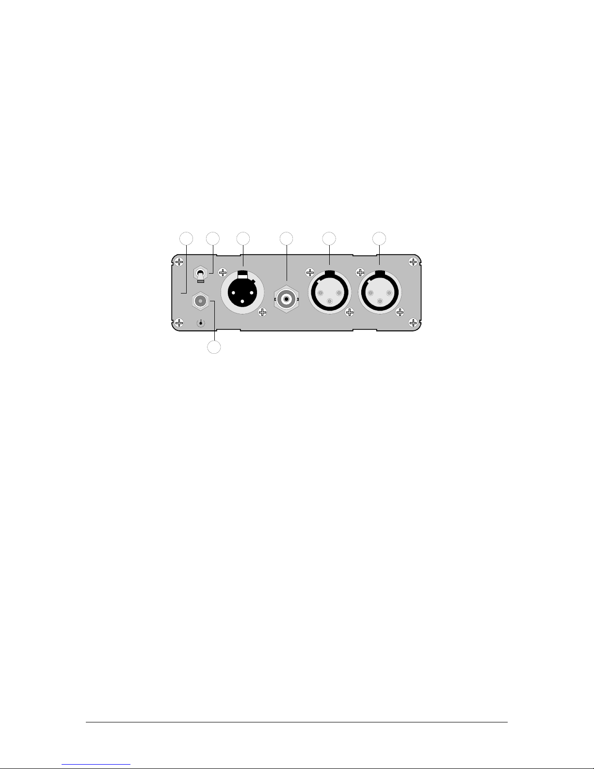
The figure below illustrates the DMIC-24’s rear panel:
AES OUT AES REF RIGHT IN LEFT IN
44.1 KHZ
MADE IN THE USA
4 5 6 7
1
PHANTOM
PWR
+6V
2
3
1) DMIC-24 Version — the printed legend indicates the default frequency (either 44.1 KHz
or 48 KHz).
2) Power Connector — accepts the power jack from the 6VDC power supply. Refer to
“External Power” for more information regarding external power.
3) Phantom Power Switch — applies 48 V phantom power to both microphone inputs,
when in the UP (on) position. In the DOWN (off) position, phantom power is not applied.
4) AES Balanced Output — provides AES balanced output via XLR connector. Output is
concurrent with the front panel’s AES unbalanced output (BNC) — both can be used
simultaneously.
5) AES Reference Input — the AES REF connector accepts an AES reference signal
(between 30 KHz and 50 KHz sampling rate). Only timing information is used; audio
content (if any) is ignored. See the “Connecting AES Reference” section for information
on switching frequencies via the reference signal.
6) Right Analog Microphone Input — accepts right channel mic level analog input. The
input level is adjustable via the Right Mic Sensitivity DIP switches on the front panel.
7) Left Analog Microphone Input — accepts left channel mic level analog input. The input
level is adjustable via the Left Mic Sensitivity DIP switches on the front panel.

DMIC-24 User Guide Page 5
DMIC-24 Installation
This section provides instructions for connecting power, microphone inputs, AES reference, and
digital outputs.
Connecting Power
Plug a 6 VDC power supply into the appropriate voltage outlet for your specific country, and
connect the end of the cord into the DMIC-24 rear panel jack marked +6V. Secure the locking
ring finger tight. The green LED on the front panel lights when power is applied.
Connecting Inputs
Connect analog microphones to the two connectors marked LEFT IN and RIGHT IN.
•Balanced sources are connected to pins 2 (+) and 3 (-) with pin 1 and the shell grounded.
•Unbalanced sources are connected to pin 2 with pins 1, 3 and the shell grounded. See
the “DMIC-24 Internal Jumpers” section for information regarding phantom power
jumpers.
Refer to the “DMIC-24 Operation” section for instructions on adjusting microphone sensitivity.
NOTE If an input is not used its sensitivity should be set to minimum.
Connecting AES Reference
The DMIC-24 can be synchronized to an alternate output frequency (from the default frequency)
by connecting a valid AES reference signal to the AES REF BNC connector. The EXT REF LED
on the front panel lights when a valid reference signal is applied.
To phase lock the unit’s sample frequency to a reference, connect a reference signal (between 30
KHz and 50 KHz sampling rate) to the AES REF BNC connector. The AES signal output will now
phase-lock to the incoming reference — independent of the DMIC’s default reference frequency.
Note that the AES REF input is normally terminated internally with 75
Ω. When it is necessary to
loop reference to several SoundPals, the signal must be terminated only once, and always at the
last unit in the chain. Refer to the “DMIC-24 Internal Jumpers” section for information on
changing the input from terminating to bridging.
Connecting Outputs
Connect the output from one of the AES OUT connectors on the front or rear panel, and route it
to the input of the desired destination device. Both AES3 and AES3id outputs may be used
simultaneously.
Using Phantom Power
If your microphone(s) require phantom power, set the Phantom Power Switch to the UP (on)
position, after connecting the mics.
NOTE When phantom power is used, a 500 mA universal power supply (with low
ripple) is required.
CAUTION If phantom power is not required for your microphone(s), be sure that the
Phantom Power Switch is in the DOWN (off) position.
Refer to the “DMIC-24 Internal Jumpers” section for information about jumpers that affect
phantom power functionality.
DMIC-24 User Guide
Page 6
DMIC-24 Operation
This section provides instructions for adjusting microphone sensitivity.
Adjusting Microphone Sensitivity
Each microphone has its own set of eight SENSITIVITY DIP switches on the front panel.
Switches (instead of potentiometers) allow you to match settings between the two channels
easily, as well as repeat recordings using specific settings when necessary.
12345678
-60
-50
-40
-30
12345678
-60
-50
-40
-30
Left Mic
Sensitivity
Adjustment
Right Mic
Sensitivity
Adjustment
Note the following important points regarding the DIP switches:
•A sensitivity setting is selected by toggling the appropriate DIP switch downwards.
•Higher sensitivity settings take precedence over lower ones (e.g., if both the -60 dB and
-40 dB settings are toggled down, the -60 dB setting overrides the -40 dB setting).
TIP If you switch between two mics with different sensitivities, switching can be
accomplished by moving just the higher sensitivity switch.
•Minimum sensitivity occurs when no switches are down.
•When using a stereo pair of microphones, ensure that both channels are set to the same
sensitivity.
To set the left and right microphone sensitivity:
1. If an input is not used, set sensitivity to minimum.
2. Have your announcer give a steady, normal voice level.
3. While watching the Level LEDs, adjust the appropriate set of SENSITIVITY switches,
until the associated -20 dB LED comes on regularly, and the -3 dB LED comes on rarely.
If the 0dB LED comes on, back off the sensitivity.
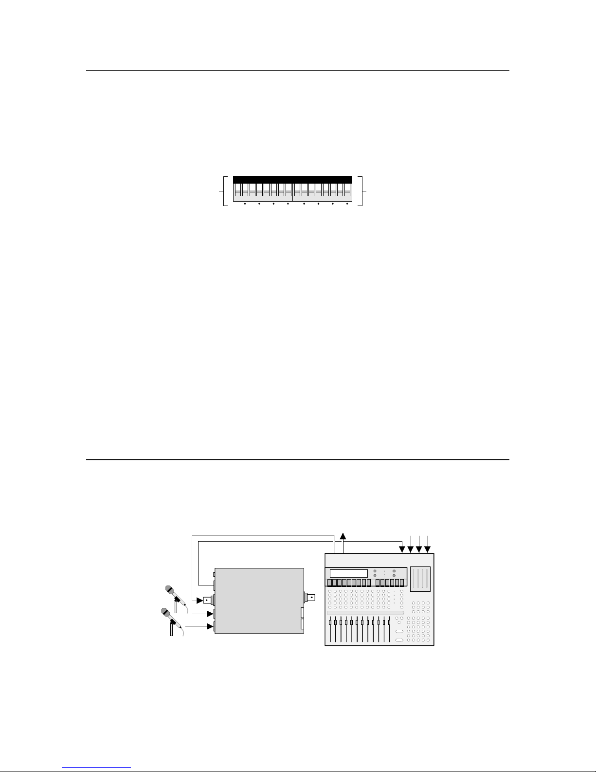
DMIC-24 Interconnection
This section provides basic and advanced interconnection diagrams.
•Basic — Analog Mic Input to Digital Mixer
Connect analog mics to the DMIC-24, and the DMIC-24’s AES output to a digital mixer.
D/ESAM Mixer
Digital Sources
Analog
Mics
Program Out Digital In
SoundPals DMIC-24
AES Out
AES Ref
Right In
Left In
PWR
Sensitivity
AES Out
Note how one of the mixer’s outputs is used to synchronize the DMIC-24 (via the AES
REF connector).

DMIC-24 User Guide Page 7
•Advanced — Sub-Mix from Analog Equipment
In this application, SoundPals are combined to provide a sub-mix (from analog
equipment). Dual mics feed the DMIC-24, and then the DMIX. An analog ATR is
converted in the ADC, routed through a DFADE for level control, and then to the DMIX.
The output of the DMIX is routed to the digital mixer for further processing.
Note that in this configuration, all SoundPals are considered synchronous.
D/ESAM Mixer
Digital
Sources
Analog
Mics
Program Out Digital In
SoundPals ADC-24
AES Out
AES Ref
Right In
Left In
PWR
R Trim
L Trim
AES Out
SoundPals DMIX-41
AES In 1
AES In 2
AES In 3
AES In 4
PWR
Control
AES Out
SoundPals DFADE-2
AES In
AES Out
PWR
R Trim
L Trim
Mode
Control
SoundPals DMIC-24
AES Out
AES Ref
Right In
Left In
PWR
Sensitivity
AES Out
DMIC-24 User Guide
Page 8
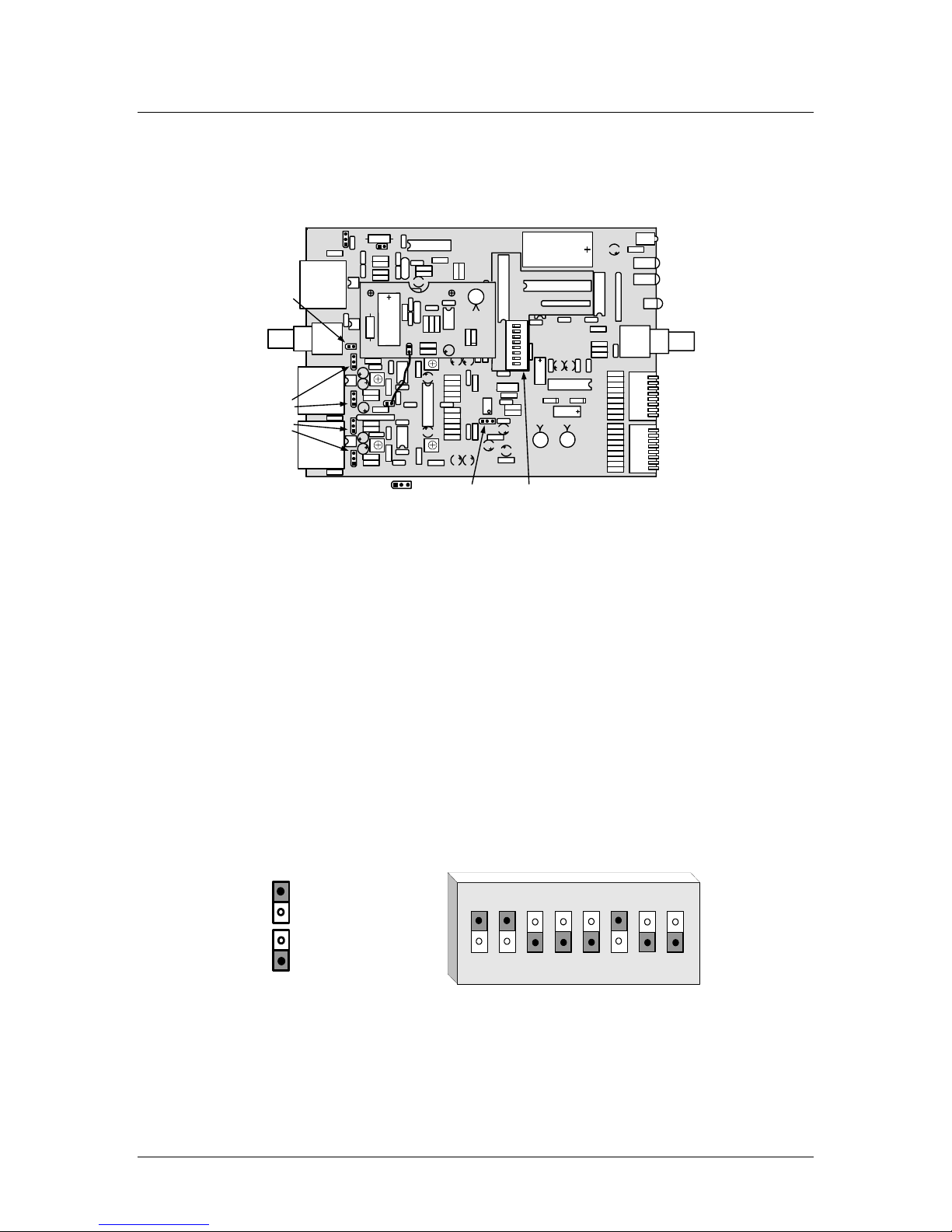
DMIC-24 Internal Jumpers
This section provides information about the DMIC-24’s internal jumpers and adjustments.
NOTE For detailed instructions on opening and closing the DMIC-24 “Inside the
Module.”
04-0237-
DMIC-24
GRAHAM-PATTEN SYSTEMS
Made in U.S.A.
GRASS VALLEY, CALIFORNIA
J10
J2
J9
04-0246-
87654321
PHANTOM POWER
J1
J5
OPEN
04-0239-
J4
J14
J15J12J13
Input
Termination
Jumper
Phantom
Power
Jumpers
High Pass
Filter Jumper
Status Bit
Dip Switch
Jumper Pinout 123
•J4 is the High Pass Filter jumper. With pins 1 and 2 connected, the filter is disabled.
With pins 2 and 3 connected, (factory default) the filter is enabled.
•To change the AES reference input from terminating to bridging, remove jumper J5.
•Jumpers J12, J13, J14, and J15 affect phantom power:
~ Jumpers J12 and J13 affect the left mic input. Jumpers J14 and J15 affect the right
mic input.
~ With pins 2-3 connected (on each of the four jumpers), phantom power is enabled.
This is the default (factory) position.
~ With pins 1-2 connected (on each of the four jumpers), phantom power is completely
disabled, even if the Phantom Power Switch is UP. This setting is recommended for
low output mics that do not require phantom power, or for any unbalanced mics.
CAUTION If you choose to change the phantom power jumpers, always change both jumpers
for the selected mic. If you do not, damage may result to your microphone.
SW1 is the Status Dip Switch that is used to set the channel status on the AES outputs. The
switch is an eight-position DIP all of which are active. Switch shows default factory switch
settings.
OPEN
1 top position
0 bottom position
12345678
For all switches:
~ 0 is open
~ 1 is closed

DMIC-24 User Guide Page 9
•Switch 3defines the Audio Mode.
Function SW3
Audio 0
Non-Audio 1
•Switches 4and 5define the Sample Frequency.
Function SW4 SW5
Not Indicated 0 0
48 kHz 1 0
44.1 kHz 0 1
32 kHz 1 1
•Switches 6and 7define the Emphasis.
Function SW6 SW7
Not Indicated 0 0
None 1 0
50/51 0 1
CCITT J.17 1 1
•Switch 8 determines the Channel Mode.
Function SW8
Not Indicated 0
Stereo 1
•If Switch 1 is Open the unit is in the Consumer Mode and the following switch settings
apply.
•Switches 2and 3define the Sample Frequency.
Function SW2 SW3
44.1 CD 0 0
48 kHz 1 0
32 kHz 0 1
44.1 kHz 1 1
•Switch 4defines the Emphasis.
Function SW4
Off 0
50/51 1

DMIC-24 User Guide
Page 10
•Switch 5defines the Copy Mode.
Function SW5
Inhibited 0
Permitted 1
•Switch 6and 7defines the Category Code.
Function SW6 SW7
General 0 0
Digital Converter 1 0
Laser, CD 0 1
Magnetic Tape 1 1
•Switch 8 determines the Generation Table.
Function SW8
1st Generation or Higher 0
Original 1
DMIC-24 Troubleshooting
The table below lists DMIC-24 problems and solutions.
Problem Procedure
No signal at either
AES output.
•Is power applied? Check power LED and power supply.
No audio on AES
output. •Is microphone connected correctly? Check +to pin 2, or ground to pin 3.
•Does microphone require phantom power? Set Phantom Power Switch to UP
(On) position.
Front panel meters
not registering.
•Is microphone sensitivity within SoundPals operating range?
•Adjust sensitivity.
Ext Ref indicator not
lit on front panel.
•Is AES reference connected? Check that an AES signal is applied to the
reference input if you want synchronized sampling.
•Is the reference input a valid AES signal?
•Is the reference input sampling frequency between 30 kHz and 50 kHz?
NOTE Please contact the GPS factory if the problem still exists after completing the
above procedures.

DMIC-24 User Guide Page 11
DMIC-24 Specifications
This section provides audio and environmental specifications.
Audio Specifications
Specification
Analog Inputs
Impedance >20 kΩ
Sensitivity -60 dBu to -20dBu (in 5dB steps) for -20 dBFS output
Frequency
Response +0/-0.1 dB, 20 Hz – 20 KHz
THD+N @ -20dBFS 92dB, sensitivity at -20dBu
84dB, sensitivity at-60 dBu
CMRR >60dB, 50 Hz – 20 KHz
Crosstalk <−84dB, 20 Hz – 20 KHz
Digital Outputs
Terminated 110
ΩAES3, 75ΩAES3id
Sample Rate 30 KHz – 50 KHz
Output resolution 24 Bit
Options
RT-2, 1RU rack tray for mounting up to 3 units
Power supplies:
•PSU-1, 90-260V 50/60Hz in-line power supply with detachable IEC power cord
NOTE All specifications listed above subject to change without notice.
Environmental Specifications and Dimensions
Parameter Specification
Dimensions
(less connectors)
5.2W x 1.62H x 6.625D
13.2 x 4.1 x 16.8 cm
Power 300mA @ 6 Vdc with Phantom Power Off.
500mA @ 6 Vdc with Phantom Power On.
Operating Temp 10 – 50
°C
Operating Humidity 10 – 90% RH non-condensing

DMIC-24 User Guide
Page 12
Inside the Module
In This Section
This section provides instructions for opening and closing the SoundPals DMIC-24 module to
gain access to the internal circuit board.
NOTE The internal circuit board should only be removed from the module if you want to set
the Phantom Power or High Pass Filter jumpers or set the Status Bit dip switch.
Before You Begin
Check the following items before opening the module and attempting to remove the internal
circuit board:
If required, remove the SoundPals module from the rack tray.
Disconnect the power supply from the front of the product.
Disconnect all input and output cables.
Perform the remaining steps only in a static free environment. Make sure that you and
the product are both grounded.
The following tools are required:
•#2 Philips screwdriver
Opening the Module
Use the following steps to open a SoundPals module:
1. On the rear panel, remove the four Phillips screws from the four corners of the
SoundPals module.
2. On the front panel, remove all Philips XLR mounting screws from the SoundPals module.
3. On the front panel remove the BNC nut and associated lock washer.
4. Pulling the rear panel, carefully draw the internal circuit board and rear panel assembly
from the housing.
CAUTION Keep the case horizontal so that the BNC bushing stays with the connectors.
5. Set the housing and all mounting hardware in a safe place.
Closing the Module
Use the following steps to close a SoundPals module:
1. Ensure that product label is on the bottom.
2. Carefully slide the internal circuit board and rear panel assembly through the housing.
Keep the case horizontal so that the BNC bushing stays with the connectors.
3. Replace the BNC nut and associated lock washer on the front panel of the module.
4. Replace all Philips XLR mounting screws on the front panel of the module.
5. Replace and tighten the four Phillips screws on the rear corners of the module.
CAUTION Do not over tighten the screws.

DMIC-24 User Guide Page 13
External Power
About Power Supplies
An external power supply conforming to the specifications listed in the following “Power Supply
Specifications” section must be used to guarantee that published SoundPals performance
figures are met. Any power supply meeting these specifications will supply adequate power for a
single SoundPals module. Although the specification is written for power supplies running from
AC line inputs, DC (battery) sources may be used if they meet all of the listed requirements.
CE Compliance
For CE compliance, the power supply that you use must comply with the following requirements:
•Low Voltage Directive 73/23/EEC
•EMC Directive 89/336/EEC
•EMC Directive 93/68/EEC
•The connector locking ring must be tight.
Portable Power Sources
For portable SoundPals power sources, sealed lead-acid, nickel cadmium or alkaline primary
batteries may be used. However, the maximum voltage must not exceed 8.6 volts, and a
minimum of 5.6 volts is required for normal operation. Maximum current drain will be 500 mA.
Power Supply Specifications
The following specifications must be met over all anticipated operating conditions including AC
power line range, temperature range, etc.
Parameter Specification
Output voltage 5.6V minimum (measured at trough of ripple) at 560 mA constant current.
8.6 V maximum (measured at peak of ripple) at 325 mA constant current.
Ripple voltage 2V p-p at 700 mA constant current.
400 mV p-p at 700mA constant current with external 2200
µF capacitor.
Connector Switchcraft 761K with center positive, sleeve negative.

DMIC-24 User Guide
Page 14
Power Supply Sources
In addition to the GPS-supplied universal power supply, the following power supplies meet the
SoundPals requirements:
Company Model Note
Stancor STA-4860 120V AC, 60 Hz
Stancor STAF-0797F 220V AC, 50 Hz with European wall plug (CE compliant).
Elpac MI2007 95-250V AC, 47-63 Hz with IEC inlet (line cord required). Will power up to six units
(CE compliant).
Note the following important points regarding the DMIC-24:
•Under normal conditions, a DMIC-24 requires about 300 mA.
•When phantom power is used, 500 mA (with low ripple) is required.
Only the GPS-supplied universal power supply or the Elpac MI2007 is satisfactory for the DMIC-
24, when phantom power is used.
Table of contents
Other SoundPals Amplifier manuals


