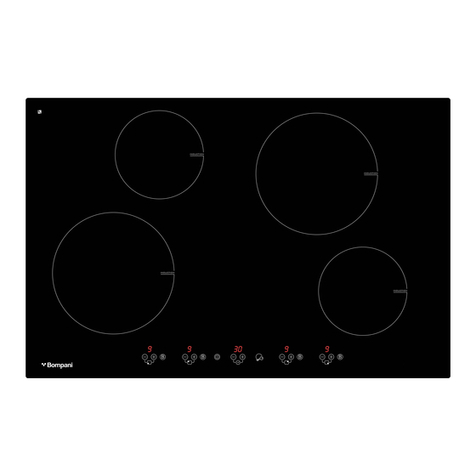
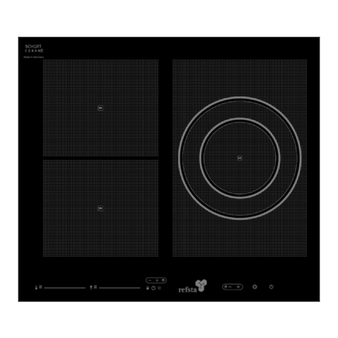
Refsta SOLITAR I User manual

PIANO COTTURA induzione ASPIRANTE
Istruzioni per l’uso IT
VITROCERAMIC COOKTOP
Users’ manual EN
GLASKERAMIKKOCHFELD
Bedienungsanleitung DE
PLAN DE CUISSON VETROCERAMIQUE
Manuel d’instructions FR
KERAMISCHE KOOKPLAAT
Gebruiksaanwijzing NL

Fig. 1

Fig. 3
Fig. 4
Fig. 2
Fig. 5
F

Fig. 6
Fig. 8
Fig. 9
Fig. 7

Fig. 10
Fig. 11
Fig. 12

Fig. 15
Fig. 13 Fig. 14
Fig. 16

Fig.17
Fig.18
Fig.19

ITALIANO
1-GENERALITA‘
Leggere attentamente il contenuto del presente libretto in quanto
fornisce importanti indicazioni riguardanti la sicurezza di
installazione, di uso e di manutenzione. Conservare il libretto per
ogni ulteriore consultazione.
Tutte le operazioni relative all’installazione (connessioni elettriche)
devono essere effettuate da personale specializzato in conformità
alle leggi e alle norme vigenti.
2-AVVERTENZE PER LA SICUREZZA
Si consigliano recipienti a fondo piatto del diametro uguale o
leggermente superiore a quello dell’area riscaldata (Fig. 6).
RECIPIENTI PER LA COTTURA
L’utilizzo di recipienti appropriati è un fattore essenziale per la
cottura ad induzione.
Verificate che le vostre pentole siano idonee per il sistema ad
induzione. Il simbolo internazionale che identifica se la pentola è
idonea alla cottura ad induzione è illustrato in Fig. 6.
I recipienti devono quindi contenere ferro.
Potete verificare se il materiale della pentola è magnetico con una
semplice calamite.
Non utilizzare recipienti con base ruvida,per evitare di graffiare la
superficie del vetro del piano. Questo apparecchio non è adatto per
l’uso da parte di bambini o persone che necessitano di supervisione.
3-IMPORTANTE
Evitare le fuoriuscite di liquido.
Non lasciare gli elementi riscaldanti accesi senza recipienti o con
recipienti vuoti.
Una volta terminato di cucinare, spegnere la relativa resistenza
tramite il comando indicato in seguito (paragrafo 8) .
Utilizzando delle friggitrici é necessario controllarle
costantemente perché l’olio surriscaldato potrebbe incendiarsi.
Se la superficie del vetro é incrinata , spegnere
l’apparecchio e disconnettere dalla rete elettrica per evitare
l’eventualità di scosse elettriche.
4-ISTRUZIONI PER L‘INSTALLAZIONE
Il produttore declina qualsiasi responsabilità per danni dovuti ad
una installazione non corretta o non conferme alle regole dell’arte
e non eseguita da personale specializzato nel rispetto delle
vigenti norme in vigore nel paese di installazione.
Nel caso in cui nella stanza vengono utilizzati simultaneamente sia la
cappa che altri apparecchi non alimentati da energia elettrica, bisogna
provvedere ad areare il locale.
Se un forno da incasso o qualsiasi altra apparecchiatura che genera
calore deve essere montato direttamente sotto il piano di cottura in
vetroceramica, E’ NECESSARIO CHE TALE APPARECCHIATURA
(forno) E IL PIANO DI COTTURA SIANO ADEGUATAMENTE
ISOLATI LASCIANDO UNA INTERCAPEDINE MINIMA COME
(Fig. 4).
Il mancato rispetto di tale precauzione potrebbe determinare l’errato
funzionamento del sistema TOUCH CONTROL.
L’elettrodomestico è realizzato per essere incassato in un piano di
lavoro, come illustrato nella figura (Fig 1). Predisporre materiale
sigillante lungo l’intero perimetro- Fig. 5. Questa operazione è
necessaria per evitare che eventuali liquidi penetrino all’interno del
piano.
Bloccare l’elettrodomestico sul piano di lavoro mediante i 4 sostegni “S”
(Fig. 2) , tenendo presente lo spessore del piano di lavoro.
Se la parte inferiore dell’apparecchio, dopo l’installazione, è accessibile
dalla parte inferiore del mobile è necessario montare un pannello
separatore rispettando le distanze indicate (Fig. 4).
5- VERSIONE ASPIRANTE / FILTRANTE
ASPIRANTE : l’aria aspirata viene purificata attraverso i filtri
antigrasso metallici e convogliata all’esterno attraverso una
canalizzazione.
5.1- USCITA ARIA SOTTO IL PIANO DI LAVORO
Montare la scatola di derivazione „F“ (Fig 15) attraverso le . 4 viti “V”
(Fig 15) . Collegare, mediante un tubo di raccordo al foro di scarico
come indicato in Fig. 13/14. Nel caso in cui l’appartamento sia dotato
di una condotta esterna per l’aria di diverso diametro applicare un
raccordo riduzione appropriato.
5.2- USCITA ARIA NELLA PARETE POSTERIORE
Smontare lo schienale „S“ (Fig 17) attraverso le n. 2 viti “V” (Fig.
17).
Montare il coperchio “T” (Fig. 19) attraverso le 4 viti “V” (Fig. 19)
Smontare il gruppo di aspirazione “G” (Fig. 17).
Eseguire i 4 fori "F" (Fig.18) nella parete posteriore, in
corrispondenza del foro di uscita aria verso l'esterno. Montare il
gruppo di aspirazione "G" (Fig.17) alla parete posteriore e
bloccare con n.4 viti. Per il fissaggio del gruppo di aspirazione
utilizzare tasselli e viti idonee al tipo di muratura della parete.
FILTRANTE: l'aria aspirata viene purificata attraverso i filtri
antigrasso "M" (Fig.12) e un filtro a carbone attivo "C"(Fig.11),
venduto separatamente. L'aria, filtrata e depurata viene rimessa
nell'ambiente interno.
Se si desidera convogliare l'aria filtrata, si può installare una
condotta collegandola alla scatola di derivazione "F" (Fig.15)
Per trasformare la cappa da versione aspirante a versione
filtrante, è necessario richiedere al vostro rivenditore il kit filtrante
e seguire le istruzioni di montaggio contenute nel Kit.
FILTRI ANTIGRASSO METALLICI (Fig.12).
I filtri antigrasso hanno il compito di trattenere le particelle
grasse in sospensione nell’aria, pertanto sono soggetti ad
intasarsi in tempi variabili relativamente all’uso dell’apparecchio.
In ogni caso, per prevenire il pericolo di eventuali incendi, al
massimo dopo 2 mesi è necessario pulire i filtri eseguendo le
seguenti operazioni:
Togliere i filtri dalla cappa "M" (Fig.12) e lavarli con una
soluzione di acqua e detergente liquido neutro, lasciando
rinvenire lo sporco.
Sciacquare abbondantemente con acqua tiepida e lasciare
asciugare.
I filtri possono essere lavati anche in lavastoviglie. Dopo alcuni
lavaggi si possono verificare delle alterazioni del colore. Questo
non dà diritto a reclamo per l’eventuale sostituzione dei pannelli.
FILTRI AL CARBONE ATTIVO (Fig.11).
I filtri al carbone attivo servono per depurare l’aria che verrà
rimessa nell’ambiente.
La saturazione del carbone attivo dipende dall’uso più o meno
prolungato dell’apparecchio, dal tipo di cucina e dalla regolarità
con cui viene effettuata la pulizia del filtro antigrasso.
Per estrarre il filtro carbone è necessario:
Smontare i filtri antigrasso metallici "M" (Fig.12), togliere il
supporto di tenuta "A" (Fig.11), tirandolo leggermente, estrarre il
filtro a carbone "C"(Fig.11).
I filtri a carbone del modello "R" (Fig. 16) sono rigenerabili:
lavare il filtro a carbone con acqua calda (65°), lasciare
asciugare poi mettere in forno a 100° per 10 minuti.
I filtri a carbone di tipo "R" sono rigenerabili fino ad un massimo
di 4 volte, dopodichè vanno sostituiti
I filtri a carbone del modello "T" (Fig.16), non sono rigenerabili e
vanno sostituiti quando esausti come indicato precedentemente.
6-CONNESSIONI ELETTRICHE (Fig.8)
Prima di effettuare le connessioni elettriche assicurarsi che:
Le caratteristiche dell’impianto siano tali da soddisfare le
indicazioni sulla targhetta identificativa applicata sulla parte
inferiore dell'apparecchio.
L’impianto sia dotato di una messa a terra efficiente conforme alle
norme e alle disposizioni di legge in vigore. La messa a terra è
obbligatoria per legge.
Nel caso in cui l’elettrodomestico non sia dotato di cavo e/o della
relativa spina, utilizzare materiale adatto per l’assorbimento
indicato nella targhetta identificativa e per la temperatura di
funzionamento.
Se si desidera una connessione diretta alla linea elettrica, è
necessario interporre un interruttore omnipolare, con un’apertura
minima di 3 mm fra i contatti, appropriato al carico indicato nella
targhetta e conforme alle norme vigenti (il conduttore di terra
giallo/verde non deve essere interrotto dal commutatore).
Terminata l’installazione dell’apparecchiatura, l’interruttore
omnipolare deve essere facilmente raggiungibile.
7-SICUREZZA
Non collegare lo scarico della cappa ad un condotto in cui circoli
aria calda o utilizzato per evacuare fumi degli apparecchi
alimentati da un’energia diversa da quella elettrica.
Nel caso in cui nella stanza vengano utilizzati sia la cappa che
apparecchi non azionati da energia elettrica si deve provvedere a
creare una aerazione sufficiente dell’ambiente.
Non fare cucine alla fiamma.
USO E MANUTENZIONE.
8-USO
Quando si accende una delle zone di cottura, l'aspirazione verrà
attivata automaticamente dopo 30 secondi e le luci si
accenderanno. Durante l'uso del piano di cottura, se si desidera,
le luci potranno essere spente. L'aspirazione potrà essere
regolata ed impostata nelle 4 diverse velocità. L'aspirazione,
durante la cottura rimarrà sempre attiva alla velocità minima.
Per un miglior funzionamento, allo spegnimento del piano di
cottura, l'aspirazione rimarrà attiva in funzione "cleaning" per un
tempo variabile da 5 a 15 minuti, in funzione del tempo di utilizzo
del piano di cottura.
Utilizzare il sistema touch control relativo alla posizione
corrispondente alle esigenze di cottura, tenendo presente che
quanto maggiore è il numero, tanto più calore viene emanato.
TOUCH-CONTROL ( Fig.10).
A- ON/OFF ASPIRAZIONE
B- AUMENTA VELOCITA’ MOTORE ASPIRAZIONE
C- DIMINUISCE VELOCITA’ MOTORE ASPIRAZIONE
E - ON/OFF DEL PIANO DI COTTURA
F- DIMINUZIONE POTENZA PIASTRE
G- SELEZIONE PIASTRA COTTURA
F + M - ATTIVA LA FUNZIONE DI TIMER
M- AUMENTA LA POTENZA DELLE PIASTRE
N- ACCENSIONE LUCI LED
L- DISPLAY
ACCENSIONE PIANO COTTURA .
Premere il tasto "E" (Fig.10), tutti i display "L" (Fig.10) relativi
alle zone di cottura si accenderanno in posizione di standby
indicando i valori ZERO.
L’unità di controllo rimarrà attiva per un tempo di 10 secondi. Se
entro questo termine non verrà selezionata nessuna zona di
cottura la funzione si disattiva automaticamente e nel caso
bisognerà ripetere la procedura.
ACCENSIONE ZONE COTTURA.
Selezionare la zona di cottura desiderata tramite i tasti "G"
(Fig.10), il relativo display di segnalazione sarà segnalato con
una luminosità più intensa indicando la zona selezionata.
Premere il tasto "+" "M" (FIG.10) oppure il tasto "-" "F"
(FIG.10). Regolare la potenza desiderata agendo sui tasti "-" e
"+" .
La potenza della singola zona di cottura può essere regolata in 9
differenti posizioni, e sarà visualizzata nel relativo display
luminoso con un numero da “1 a 9”.
FUNZONE BOOSTER
La funzione booster consente di avere a disposizione una potenza
più elevata per 5 minuti.
Per attivare la funzione booster, selezionare la zona di cottura
desiderata tramite i tasti G Fig.10, portare, tramite il tasto + la
potenza a livello 9, rilasciare il tasto + e premere nuovamente il
tasto +, il display segnalerà l'inserimento del booster con il
simbolo , Il Booster rimarrà attivato per 5 minuti.
Per disattivare il booster, premere la zona di cottura desiderata(G
Fig.10),premere il tasto - (F Fig.10) ed impostare il nuovo livello
di potenza.
CALORE RESIDUO
Se la temperatura di una zona di cottura, dopo essere stata
spenta è ancora elevata , il display relativo mostra il simbolo
“ H “ (calore residuo). L’indicazione scompare quando la
temperatura della zona sarà al di sotto dei 50° circa.
RILEVAMENTO PENTOLE
Le zone di cottura sono sensibili al diametro delle pentole, il
diametro minimo delle pentole da utilizzare è di mm 120 per le
zone di cottura più grandi e di mm. 80 per le zone di cottura più
piccole. Nel caso in cui la pentola è troppo piccola e/o è assente,
nel display corrispondente (L Fig.10) viene segnalato con il simbolo
TIMER
Questa funzione permette di stabilire il tempo (da 1 a 99 minuti)
per lo spegnimento automatico della zona di cottura selezionata.
Il Timer può essere utilizzato solo se la zona di cottura che si
vorrà temporizzare è accesa. Per attivare il timer accendere e
regolare la temperatura della zona di cottura desiderata.
Selezionare la zona di cottura desiderata poi premere
contemporaneamente i tasti “-" e “+" "M-F" (Fig.10) .
i due display della zona superiore indicheranno i valori di zero,
con il tasto "+" impostare il tempo desiderato. Confermare
premendo il tasto "G" (Fig.10) relativo alla zona desiderata.
L'operazione si può ripetere per tutte le zone di cottura. Le zone
di cottura, impostate con il timer, saranno evidenziate con un
punto (P Fig.10)vicino al display della zona corrispondente.
Per visualizzare il tempo residuo del timer, premere il tasto "G"
(Fig.10) e contemporaneamente i tasti - e + , nei due display
superiori verrà visualizzato il tempo residuo. Per uscire dalla
modalità di visualizzazione, attendere 10 secondi oppure premere
di nuovo il tasto "G".
Per disattivare il timer, spegnere la relativa zona di cottura,
oppure diminuire il tempo fino ad arrivare a zero.
Trascorso il tempo del timer impostato la zona di cottura si
spegnerà e verrà segnalato con un segnale acustico e i due
display del tempo lampeggeranno. Per disattivare il segnale
acustico premere un qualsiasi tasto.
FUNZIONE COUNTDOWN.
La funzione Countdown può essere inserita sia a piano accesso
che a piano spento. Ha gli stessi tempi del timer (1 a 99 minuti)
ma al contrario del timer essa non prevede lo spegnimento delle
zone di cottura.

A piano spento
Premere contemporaneamente su i tasti + e –, Impostare il
tempo desiderato
A piano accesso, senza selezionare un elemento particolare,
riprodurre la stessa procedura del countdown a pianto spento.
BLOCCO COMANDI (Child-lock)
E’ possibile bloccare i comandi per evitare il rischio di modifiche
non intenzionali alle regolazioni (bambini, operazioni di pulizia,
ecc.).
Premere contemporaneamente il tasto in basso a destra ed il
tasto "-" come illustrato in Fig 10), rilasciare i 2 tasti
e premere di nuovo il tasto in basso a destra. Il
display mostrerà il simbolo
Per disattivare momentaneamente il blocco comandi, ripetere la
procedura come precedentemente descritto.
Per disattivare definitivamente il blocco comandi, premere
contemporaneamente il tasto in basso a destra ed il tasto "-"
come illustrato in Fig 10), rilasciare i 2 tasti e premere di nuovo il
tasto "-".
SPEGNIMENTO ZONE COTTURA
Per spegnere una zona di cottura. Selezionare la zona desiderata,
il display apparirà di luminosità più intensa, con il tasto ( - )
andare fino a livello ZERO
SPEGNIMENTO DI SICUREZZA
L’apparecchio è provvisto di un sistema di sicurezza che spegne
automaticamente le zone cottura trascorso il tempo limite di
accensione ad una data potenza.
POTENZA AUTO-OFF in ORE
1 8,5 h
2 – 3 6 h
4 – 5 4 h
6 2,8 h
7 2,3 h
8 1,8 h
9 1,5 h
9-MANUTENZIONE
Il buon funzionamento dell'apparecchio è condizionato
dall’assiduità con cui sono effettuate le operazioni di
manutenzione, in modo particolare, del filtro antigrasso, e del
filtro al carbone attivo.
Pulire frequentemente tutte le superfici dell'apparecchio usando
un panno inumidito con acqua e detersivi liquidi neutri non
abrasivi.
Evitare, getti d’ acqua, diluenti, solventi, alcol e sostanze
abrasive.
Rimuovere eventuali residui di cibo e gocce di unto dalla superficie
di cottura utilizzando lo speciale raschietto (opzionale). Pulire l’area
riscaldata nel miglior modo possibile utilizzando prodotti idonei ed
un panno-carta, quindi sciacquare con acqua e asciugare con un
panno pulito.
AVVERTENZA-
Mediante lo speciale raschietto (opzionale) rimuovere
immediatamente dall’area riscaldata di cottura frammenti di fogli di
alluminio e materiale plastico scioltisi inavvertitamente o residui di
zucchero o di cibi ad elevato contenuto di zucchero. In questo
modo si evita ogni possibile danno alla superficie del piano. In
nessun caso si devono utilizzare spugnette abrasive o detergenti
chimici irritanti quali spray per forno o smacchiatori.
12-DISMISSIONE DEGLI ELETTRODOMESTICI
Direttiva Europea 2002/96/CE sui rifiuti di apparecchiature
elettriche ed elettroniche (RAEE). Gli apparecchi dismessi
devono essere raccolti separatamente per ottimizzare il tasso di
recupero e riciclaggio dei materiali che li compongono ed
impedire potenziali danni per la salute e l’ambiente. Il simbolo del
cestino barrato è riportato su tutti i prodotti per ricordare gli
obblighi di raccolta separata. Per ulteriori informazioni, sulla
corretta dismissione degli elettrodomestici, i detentori potranno
rivolgersi al servizio pubblico preposto o ai rivenditori.
SI DECLINA OGNI RESPONSABILITA’ PER EVENTUALI DANNI
PROVOCATI DALLA INOSSERVANZA DELLE SUDDETTE
AVVERTENZE. LA GARANZIA NON E’ VALIDA NEL CASO DI DANNI
PROVOCATI DALL’INOSSERVANZA DELLE SUDDETTE
AVVERTENZE.

ENGLISH
1 - GENERAL
Carefully read the contents of this leaflet since it provides
important instructions regarding safety of installation, use and
maintenance. The operating instructions should be retained for
future reference.
All the operations relating to installation (electrical connections)
must be carried out by specialised personnel in accordance with
current regulations .
2-SAFETY INSTRUCTIONS
It is best to use flat bottomed pans with a diameter equal to or
slightly larger than that of the heating area. (Fig.6).
COOKING POTS
The use of appropriate cooking pots is an essential factor for
induction cooking.
Make sure your pots are suitable for induction system. The
international symbol identifying suitable pots for induction cooking
is illustrated in Figure 6.
Cooking pots should contain iron.
You can verify if the material of the cooking pots is magnetic by
using a magnet.
To reduce the chances of scratching the surface of the glass cook
top, avoid using rough bottomed pots. This appliance is not
intended for the use by children or infirm person without
supervision.
3-IMPORTANT
Avoid leakage of liquid.
Do not leave heated cooking areas without tops or with empty
tops.
Once you finished cooking , switch off the related cooking area as
indicated (paragraph 8) .
Constantly check deep fryers while using them as overheated oil
could catch fire.
If the surface of the hob is cracked, turn off the appliance
and disconnect it from the main supply in order to avoid
any possible electric shocks.
4-INSTALLATION INSTRUCTIONS
The manufacturer disclaims any liability for damage due to
improper installation or not in accordance with the best working
standards and not performed by qualified personnel in
compliance with current regulations in force in the country of
installation.
If the cooker hood is used simultaneously with appliances
powered by a non-electric energy source, the room must have
sufficient ventilation.
If the built-in oven or any other appliance generating heat, is
fitted directly under the glass ceramic cook top, AN
ADEQUATED GAP TO INSULATE THE COOKTOP AND THE
OTHER APPLIANCE HAS TO BE PROVIDED , AS SHOWN IN
(Fig. 4).
Failure to observe this precaution could cause wrong operation of
the TOUCH CONTROL.
The appliance is designed to be built in a worktop, as shown in (Fig
1). Provide sealing material along the entire perimeter (Fig 5). This
is necessary to prevent any liquid from getting inside the cooktop.
While fixing the appliance into the worktop with the 4 supports “S”
(Fig. 2) , bear in mind the thickness of the worktop.
If, after installation, the bottom of the appliance, is accessible
from the bottom of the cabinet it is necessary to mount a
separating panel at the specified distances (Fig. 4).
5- EXTRACTION / RECIRCULATION VERSION
EXHAUST : the exhausted air is cleaned by passing through the
metal grease filters and then conveyed outside through a ducting
pipe.
5.1- LOWER AIR OUTLET
Fasten the junction box "F" (Fig 15) through 4 screws "V" (Fig 15).
Connect through a connecting tube to the air outlet as shown in Fig
13/14. If the external pipe ducting has a different diameter, apply a
proper reduction fitting.
5.2- REAR WALL AIR OUTLET
Loosen the back panel „S“ (Fig 17) by unscrewing the 2 screws
“V” (Fig. 17).
Fix cover “T” (Fig. 19) by means of the 4 screws “V” (Fig. 19)
Loosen motor unit “G” (Fig. 17).
Drill 4 holes "F" (Fig.18) at the rear wall outlet. Fix the motor unit
"G" (Fig.17)to the rear wall with 4 screws. To fix the motor unit to
the wall ensure you use suitable plugs and screws.
RECYCLING: the exhausted air is cleaned by passing through the
grease filters "M" (Fig.12) and an active carbon filter
"C"(Fig.11) - sold separately. The recycled air is reintroduced
into the kitchen.
If you want to convey the recycled air, install a duct, connecting it
to the junction box "F" (Fig.15)
To convert the hood from ducting to a recycling version, ask your
retailer the recycling kit and follow the instructions contained .
METAL GREASE FILTERS (Fig.12).
The metal grease filters are used to hold any grease particle
suspended in the air, and are therefore subject to saturation
depending on the use of the appliance.
In any case, to avoid fire hazard, filters should be cleaned at
least every 2 months as follows:
-
remove the filters from the cooker hood
"M" (Fig.12)
and leaving them to soak, wash them in a solution of
water and neutral liquid detergent;
-
rinse thoroughly with warm water and leave to dry.
Filters may also be cleaned in a dishwasher. The aluminium filters
may alter in colour after several washings. This doesn’t give any
right on replacement of the filters.
ACTIVE CARBON FILTER (Fig.11)
The active carbon filters purify the kitchen vapours, the air is then
reintroduced into the kitchen.
The saturation of the active carbon depends on the frequency of
the appliance’s use, the type of cooking and the regularity of
cleaning of the metal grease filters.
To remove the carbon filter, it is necessary to:
remove the metal grease filters "M" (Fig.12), remove the
supports "A" (Fig.11), pull slightly to remove the carbon filter
"C"(Fig.11).
The carbon filters Type R
(Fig. 16) are recyclable : wash the
carbon filter with warm water (65°), leave to dry and then put in
the oven at 100 ° for 10 minutes.
The carbon filters Type R
(Fig.16)
are recyclable up to maximum 4
times and then should be replaced.
The carbon filters Type T
(Fig.16)
are not recyclable and should be
replaced when saturated as previously described
.
6-ELECTRICAL CONNECTIONS (Fig.8)
Before carrying out the electrical connections, make sure that :
the systems’ features meet the indications on the rating plate
applied on the underside of the appliance .
the system is foreseen of and efficient grounding in accordance
with the laws and current standards. Grounding is mandatory by
law.
If the appliance is not supplied with a cable and/or suitable plug,
use material suitable for the absorption value indicated on the
rating plate and for the operating temperature.

If wishing to make a direct connection to the mains supply , an
omnipolar switch must be installed with a minimum 3 mm
opening between the contacts and appropriate for the charge
indicated on the plate and in accordance with current standards
(the yellow/green ground conductor must not be disconnected by
a switch). When the appliance has been installed, the omnipolar
switch must be easily reachable.
7-SAFETY INSTRUCTIONS
Do not connect the cooker hood air outlet to the same duct used
for hot air circulation or to evacuate fumes from other appliances
supplied by other than an electrical source.
If the cooker hood is used simultaneously with appliances
powered by a non-electric energy source, sufficient ventilation in
the room has to be provided.
Do not flambé food under the cooker hood.
USE AND MAINTENANCE
8-USE
If one of the cooking areas is switched on , the cooker hood and
the lighting will automatically be switched on after 30 seconds.
During the use of the hob , lighting can be switched off if
desirable. Fan speed can be adjusted and set up in 4 different
speeds. The fan will always run at minimum speed while cooking.
For a better operation, if the cooking top is switched off, the fan
continues running in the "cleaning" function for a period variable
from 5 to 15 minutes, depending on the operating time of the
cooking top.
Use the touch control to insert the necessary working heat ,
considering that the higher the number , the hotter the plates will
be .
TOUCH-CONTROL ( Fig.10).
A. ON/OFF FAN EXTRACTOR
B. INCREASE OF THE EXTRACTOR FAN MOTOR SPEED
C. DECREASE OF THE EXTRACTOR FAN MOTOR SPEED
D. --
E. ON/OFF HOB
F. DECREASES COOKING AREAS POWER
G. SELECT COOKING AREA
F + M. ACTIVATS TIMER FUNCTION
M. INCREASES COOKING AREAS POWER
N. LED LIGHTING ON
L. DISPLAY
SWITCHING THE HOB ON
Press button “E” (Fig.10), all the display "L" (Fig.10)
corresponding to the cooking areas will be lit in a standby
position, showing a 0 position.
The control unit remains active for 10 seconds. If no cooking area
is selected within this time, the hob switches off automatically
and in this case the operation should be repeated.
SWITCHING THE COOKING AREA ON
Select the desired cooking area using the keys "G" (Fig.10), the
light signal "S" will show the selected area.
Press the key "+""M" (Fig.10) or the key "-" "F" (Fig.10). Set
the desired power pressing the key "-" or "+".
The power of the single cooking area can be adjusted in 9 different
positions and will be shown on the related display with a number
from “1 to 9”.
BOOSTER FUNCTION
This function allows to have a higher power for 5 minutes on the
selected cooking area .
Select the cooking area with the button G Fig. 10 , put the power
up to level 9 with button + , release the button + and press once
more on button +, the display will show the simbol meaning
the booster function is activated. The booster function will be
activated for 5 minuts.
To turn off the booster , select the desired cooking area (G
Fig.10), press button - (F Fig.10) and set up the requested power
level .
RESIDUAL HEAT
If the temperature of a cooking area still is high after it has been
switched off , the display shows the simbol “ H “ (residual
heat) . This indication will disappear once the cooking area
temperature drops below 50°.
POT DETECTION
The cooking areas are sensible at the pot diamter . The minimum
pot diameter to be used is of 120mm for the large cooking areas
and of 80 mm for the smaller cooking areas. Should the pot be to
small or not present at all , the symbol
will appear on the display (L Fig. 10).
TIMER
This function allows to switch off automatically the cooking areas
selected within a period going from 1 to 99 minutes.
The timer can only be used if corresponding cooking area is
switched on . To set up the timer , switch on the cooking area
and adjust its power. Select the cooking area and simultaneously
press buttons “-" and “+" "M-F" (Fig.10).
The two displays of the upper areas will indicate the value ZERO.
Press on button "+" to set up the time of the timer. Confirm by
pressing on button "G" (Fig.10) of the related cooking area. This
operation can be repeated for all the cooking areas. The selected
cooking areas will be pointed out with a dot (P Fig.10)
appearing next to the related area.
To display the remaining time , press button "G" (Fig.10)
simultaneously to buttons – and + , on the two upper displays
the residual time will be shown. To exit viewing mode , wait 10
seconds or press once more button "G".
To disactive the timer, switch off the related cooking area or
decrease the time up to zero.
When the time of the timer is expired , the cooking area will be
switched off , a sound signal will indicate time is expired and both
displays will blink. To disactivate the sound signal push one
button.
COUNTDOWN FUNCTION
This function can be inserted either with switched on or off hob.
Countdown function has the same periods as the timer (from 1 to
99 minutes) . This function doesn’t forsee automatical switch off
of the cooking areas.
With switched off hob
Push simultaneously button + and -. Set up the desired time.
With switched on hob without selecting a specific cooking
area go ahead as described above.
CHILD LOCK
To prevent unintentional modification of the settings ((by
children, during cleaning etc.), it is possible to block the control
panel with the child lock.
Press simultaneously the lower right button and the "-" button
(as shown in Fig 10), release both buttons and press
again the lower right button. Your display will show
the symbol
To disactivate temporarily the control panel , repeat the above
indicated procedure .

To definitively disactivate the control panel , press
simultaneously the lower right button and the "-" button as
indicated in Fig 10, release both buttons and press once more on
the "-" button.
SWITCHING THE COOKING AREA OFF
To switch off a cooking area , select the area. The display will
appear brighter . Press button ( - ) until level ZERO is reached.
SAFETY SWITCH OFF
The appliance is provided with a safety system , switching off
automatically the cooking areas after a given working time at a
given power level.
POWER AUTO-OFF in HOURS
1 8,5 h
2 – 3 6 h
4 – 5 4 h
6 2,8 h
7 2,3 h
8 1,8 h
9 1,5 h
9-MAINTENANCE
The proper function of the appliance is related to regularity of the
maintenance operations, in particular with regards to the grease
filter and the active carbon filter.
Frequently clean all surfaces of the appliance using a cloth
dampened with water and neutral non-abrasive liquid detergent.
Avoid the use of water jets', thinners, solvents, alcohol or
abrasives substances.
Remove any remaining food or grease droplets from the hob’s
surface using a special scraper (optional). Clean the heated area
as thoroughly as possible using suitable products, and a
cloth/paper, where after rinse with water and dry with a clean
cloth.
WARNING
Using a special scraper (optional), immediately remove any
fragments of aluminium and plastic material that have
unintentionally melted on the heated cooking area, or residues of
sugar or food with a high sugar content.
In this way, any damage to the hob’s surface can be prevented.
Under no circumstances should abrasive sponges, or corrosive
chemical detergents, such as oven sprays or stain removers, be
used.
12-
DISPOSAL OF OLD ELECTRICAL APPLIANCES
The European Directive 2002/96/EC on Waste Electrical and
Electronic Equipment (WEEE), requires that old household
electrical appliances must not be disposed of in the normal
unsorted municipal waste stream. Old appliances must be
collected separately in order to optimise the recovery and
recycling of the materials they contain and reduce the impact on
human health and on the environment.
The crossed-out dustbin symbol on the product reminds you of
your obligation regarding separated waste collection. Consumers
should contact their local public service or their local dealer for
more information on the correct disposal of household
appliances.
THE MANUFACTURER DECLINES ALL RESPONSIBILITY FOR
EVENTUAL DAMAGES CAUSED BY NOT FOLLOWING THE
ABOVE WARNINGS. THE WARRANTY IS NOT VALID IN
CASE OF DAMAGE CAUSED BY FAILURE TO COMPLY WITH
THE ABOVE-MENTIONED WARNINGS.

Elektro-Glaskeramik-Induktions-
Kochfeld
Montage- und Gebrauchsanweisung
1-ALLGEMEIN
Bitte lesen Sie diese Anweisung sorgfältig, da es wichtige
Informationen über die sichere Installation, Gebrauch und Wartung
enthält und behalten Sie diese für zukünftige Referenz.
Alle Handlungen im Zusammenhang mit die Installation (elektrische
Anschlüsse) müssen von qualifiziertem Personal in Übereinstimmung mit
den Gesetzen und Vorschriften durchgeführt werden.
2-SICHERHEITSANWEISUNGEN
Benutzen Sie bitte Töpfe mit flachem Boden deren Durchmesser gleich oder etwas
grösser als der beheizten Fläche ist (Abb. 6).
KOCHTÖPFE
Die Verwendung von geeigneten Kochtöpfen ist ein wesentlicher
Faktor für Induktionsherden.
Bitte überprüfen Sie, dass Ihre Töpfe für Induktionsherden
geeignet sind.In Abbildung 6 finden Sie dasinternationales
Symbol für Töpfe und Pfanne die für Induktion geeignet sind.
Die Töpfer und Pfanne müssen daher Eisen enthalten.
Mit einem einfachen Magneten können Sie überprüfen, ob das
Material der Topf magnetisch ist.
Das Kochgeschirr darf keinen rauen Boden haben, um das
Glaskeramik nicht zu verkratzen. Das Gerät ist nicht für die
Benutzung durch Kinder geeignet.
3-WICHTIGE HINWEISEN
Vermeiden Sie Verschüttung.
Lassen Sie nie die Kochplatte ohne Töpfe oder leere Töpfe eingeschaltet.
Schalten Sie nach jedem Gebrauch die Kochplatte aus (Absatz 8).
Fritteusen sollten ständig überprüft werden , überhitztes Öl kann
sich entzünden.
Wenn die Glasoberfläche gerissen ist, soll das Gerät ausgeschalten und
vom Stromnetz getrennt werden, um Stromschlag zu vermeiden
4-MONTAGEANWEISUNGEN
Der Hersteller übernimmt keine Haftung für Schäden, die durch
unsachgemäße Installation oder die nicht den Regeln
übereinstimmen und nicht von Fachpersonal unter Einhaltung der
geltenden Vorschriften im Land der Installation durchgeführt
worden sind.
Falls im Raum sowohl die Abzugshaube als auch Geräte benutzt
werden, die nicht mit Elektroenergie betrieben werden, ist für
eine ausreichende Belüftung zu sorgen
Sollte unter dem Glaskeramikfeld ein Einbaubackofen oder ein
sonstiges Elektrogerät, das Wärme erzeugt, installiert sein,MUSS
DAS GLASKERAMIKFELD MIT GEEIGNETEM DÄMMMATERIAL
GEGEN DIESE TEMPERATUREINFLÜSSE SO ISOLIERT WERDEN,
WIE IN DER ABBILDUNG ANGEGEBEN (ABB.4).
Die Nichtbeachtung dieser Vorsichtsmaßnahme könnte zu
Fehlfunktionen des TOUCHCONTROL-Systems führen.
Das Gerät soll in eine Arbeitsplatte eingebaut werden, wie in der
Abbildung (Abb. 1) gezeigt. Die Dichtung ist um den Umfang
anzubringen - Abb. 5. Es dürfen keine Flüssigkeiten in das Innere des
Gerätes gelangen.
Die Befestigung des Glaskeramikfeldes im Ausschnitt der
Arbeitsplatte erfolgt mit den mitgelieferten Klammern "S"
(Abb.2), in Anbetracht der Stärke der Arbeitsplatte (Abb.2 ).
Wenn die Untere Seite des Glaskeramikfeldes nach der Montage
von unten her berührbar ist, muss ein Trennboden eingebaut
werden, der diese Möglichkeit ausschließt. Die einzuhaltenden
Maßen sind in der Abbildung (Abb. 4 ) angegeben.
5- ABLUFT- /UMLUFTBETRIEB
ABLUFT: die Luft wird durch einen Metallfettfilter gereinigt und
dann durch ein Abzugsrohr nach außen abgeführt.
5.1- UNTEN LUFTAUSTRITT
Montieren Sie die Anschlussdose "F" (Abb.15) mit die 4
Schrauben "V" (Abb.15). Schließen Sie das Abluftrohr an einer
Luftaustritt an (Abb.13/14). Wenn das Außenluftrohr einen
verschiedenen Durchmesser hat, verwenden Sie einen geeignetes
Reduzierstück.
5.2- HINTEN LUFTAUSTRITT
Lösen Sie die 2 Schrauben „V“ (Abb. 17) und entfernen Sie die
Rückwand „S“ (Abb. 17).
Abdeckung „T“ (Abb. 19) durch die 4 Schrauben "V" (Abb.19)
befestigen. Der Motoreinheit „G“ (Abb.17) entfernen.
4 Löchern "F" (Abb.18) am Luftaustritt der Rückwand bohren.
Der Motoreinheit “G” mit 4 Schrauben am Rückwand befestigen
(Abb.17). Zur Befestigung der Motoreinheit verwenden Sie Dübel
und Schrauben die zur Mauerwerks passen.
UMLUFTBETRIEB : die Luft wird durch die Fettfilter "M" (Abb.12)
und einen Aktivkohlefilter "C"(Fig.11), separat erhältlich,
gereinigt. Die gefilterte und gereinigte Luft wird in die Küche
zurückgeführt.
Wenn Sie die gereinigte Luft leiten möchten, können Sie ein Rohr
an die Anschlussdose "F" (Abb.15) anschliessen.
Wenn Sie die Ablufthaube in einer Umlufthaube verwandeln
möchten, bitte wenden Sie sich an Ihren Händler, damit dieser
Ihnen ein Kit für dem Umluftbetrieb verkauft. Den im Kit
enthaltenen Anweisungen folgen.
METALLFETTFILTER (Abb.12)
Metallfettfilter filtern die eingesaugten Fettpartikel aus den
Kochwrasen und halten diese fest. Die Sättigung der Filter hängt
von der mehr oder minder langen Benutzungsdauer des Gerätes
ab.
Um Feuergefahr zu vermeiden, sollten Sie die Filtern spätestens
alle 4 Wochen reinigen. Folgenden Handlungen durchführen:
Entfernen Sie die Filter aus der Hauben "M" (Abb.12).
Lassen Sie die Filtern für ca. eine Stunde in heißem Wasser mit
fettlösendem Reinigungsmittel einweichen und danach mit
heißem Wasser abspülen. Lassen Sie die Filtern gut trocknen. Die
Filtern können im Geschirrspüler gewaschen werden.
Bei die Reinigung der Fettfilter kann es zu Verfärbungen der
Filterflächen kommen. Dies gibt kein Recht auf Ersatzanfrage der
Fettfiltern.
AKTIVKOHLEFILTER (Abb.11)
Die Aktivkohlefilter dienen dazu, die Luft zu reinigen, die wieder
in den Raum zurückgeführt wird.
Die Sättigung der Aktivkohle hängt von der Nutzung des Gerätes,
der Art des kochens ab.
Um die Aktivkohlefilter auszuwechseln, wie folgt vorgehen :
Entfernen Sie die Metallfettfilter „M“ (Abb. 12). Ziehen Sie den
Halter „A“ (Abb. 11) und den Aktivkohlefilter „C“ (Abb. 11)
heraus.
Die Aktivkohlefilter Type "T" (Abb.16) sind nicht regenerierbar
und müssen ausgetauscht werden wie oben angegeben.
6-STROMANSCHLUSS (Abb. 8)
Vor den elektrischen Anschluss ist sicherzustellen, dass :
die Elektroanlage Kennzeichen übereinstimmen mit die auf dem Typenschild
angegebene Daten .
Die Elektroanlage muss mit einem den gesetzlichen Vorschriften
entsprechende Erdung ausgestattet ist. Die Erdung ist gesetzlich vorgeschrieben.

Bei Direktanschluss an die Elektroanlage soll eine geeignete allpolige
Trennvorrichtung mit einer Kontaktöffnung von mindestens 3 mm eingesetzt werden (der
Kommutator darf die gelb/grüne Erdleitung nicht unterbrechen).
Dieser Hauptschalter muss jederzeit gut zugänglich sein.
7-SICHERHEITSHINWEISE
Schlieǃen Sie die Dunstabzugshaubeluftaustritt nie an
Luftungssysteme für Warmluft oder Luftaustritte von nicht
elektrisch betriebene Geräte an.
Falls im Raum neben die Dunsthaube auch nicht elektrisch
betriebene Geräte benutzt werden, ist für eine ausreichende
Belüftung zu sorgen.
Flambieren Sie niemals unter die Dunsthaube !
BETRIEB UND WARTUNG
8-BETRIEB
Wenn Sie eine Kochplatte einschalten, wird die Absaugung nach
30 Sekunden automatisch anlaufen und die Beleuchtung
eingeschaltet. Während des Betriebs können Sie die Beleuchtung
wenn wünschbar, ausschalten. Die Betriebsstufen können in vier
Geschwindigkeiten eingestellt worden. Während des Kochens
wird die Dunstabzugshaube mit minimaler Geschwindigkeit
immer betrieben.
Für einen besseren Betrieb wird die Haube nach Ausschaltung des
Kochflaches , von 5 bis 15 Minuten - abhängig vom Kochzeit -
aktiv in der Funktion "Reinigung" verbleiben.
Wählen Sie durch Drücken der Sensortasten die gewünschte
Betriebsstufe aus. Wobei Stufe 1 für die niedrigste und Stufe 9 für
die höchste Temperatur steht.
TOUCH-CONTROL ( Fig.10).
A. EIN/AUSSCHALTUNG DUNSTHAUBE
B. MOTORGESCHWINDIGKEIT PLUS
C. MOTORGESCHWINDIGKEIT MINUS
D. SCHLÜSSELTASTE (KINDERSICHERUNG)
E. EIN/AUS-SCHALTUNG KOCHFELD
F. LEISTUNGSTUFE KOCHPLATTE MINUS
G. AUSWAHLTASTE DER KOCHPLATTE
F. + M. TIMER FUNKTION
M. LEISTUNGSSTUFE KOCHPLATTE PLUS
N. BETÄTIGUNG LED BELEUCHTUNG
L. DISPLAY
KOCHFELD EINSCHALTUNG
Drücken Sie die Tasten "G" (Fig.10), um die gewünschte
Kochplatte zu wählen, die Signallampe "S" zeigt die ausgewählte
Kochplatte an.
Die Kontrolleinheit bleibt für die Dauer von 10 Sekunden
eingeschaltet. Wird innerhalb dieser Zeitraum das Kochfeld nicht
betätigt, geht die Elektronik automatisch wieder auf die OFF-
Position über. Es muss dann der eben beschriebene Vorgang
wiederholt werden, um das Kochfeld einzuschalten.
KOCHPLATTE EINSCHALTUNG
Drücken Sie die Tasten "G" (Fig.10), um die gewünschte
Kochplatte zu wählen, die Signallampe "S" zeigt die ausgewählte
Kochplatte an.
Drücken Sie die Tasten "+" "M" (FIG.10) oder "-" "F" (Abb.
10). Stellen Sie die gewünschte Leistungsstufe durch Drücken
der Tasten "-" und "+" ein.
Die Leistung der einzelnen Kochzonen kann in 9 verschiedene
Positionen eingestellt werden und wird über den hellen Display
mit einer Zahl von “1 bis 9” angezeigt.
BOOSTER FUNKTION
Der Booster erlaubt eine erhöhte Leistung für eine Dauer von 5
Minuten.
Um dem Booster einzuschalten soll die gewünschte Kochplatte
mit Taste F (Abb. 10) gewählt werden. Drücken Sie auf die +
Taste bis Stand 9, lassen Sie die Taste + los . Auf das Display
wird das Symbol erscheinen. Der Booster wird für 5
Minuten eingeschaltet bleiben.
Um die Funktion auszuschalten , die gewünschte Kochplatte (G –
Abb. 10) wählen , Taste - (F Abb.10) drücken und die
gewünschte Betriebsstand einsetzen.
RESTWÄRMEANZEIGE
Wenn eine Kochplatte ausgeschaltet ist und ihre Temperatur
noch hoch ist, bleibt die Anzeige (Restwärme)
eingeschaltet. Diese Anzeige erlischt erst, wenn die Temperatur
der Kochplatte unter 50° gefallen ist.
TOPFERKENNUNG
Die Kochplatte sind sensibel an den Durchmesser der Kochtopfen.
Der Minimum Durchmesser soll 120 mm für die groȕere Kochplatten und 80 mm für die
kleinere sein. Wenn der Kochtopfen entweder zu klein oder überhaupt nicht auf die
Kochplatte steht , wird auf dem Display (L – Abb. 10) das Symbol
eingeschalten.
ZEITSCHALTUHR (TIMER)
Durch Einschaltung der Zeitschaltuhr ist es möglich eine Zeit von
1 bis 99 Minuten einzustellen für der automatischer Ausschaltung
der Kochplatten.
Der Timer kann nur verwendet werden, wenn die Kochplatte
eingeschaltet ist. Um den Timer zu aktivieren, die gewünschte
Leistungsstufe der Kochplatte einstellen. Wählen Sie die
gewünschte Kochplatte und drücken Sie gleichzeitig die Tasten "-
" und "+" "MF" (Abb. 10).
Der Anzeige der beiden oberen Bereichen werden als Wert Null
angeben, mit der Taste "+" die gewünschte Zeit einstellen.
Bestätigen Sie mit die Taste "G" (Abb. 10) der gewünschten
Bereich. Der Vorgang kann für alle Kochplatten wiederholt
werden. Die mit der Zeitschaltuhr gewählte Kochplatten, werden
mit einem Punkt (P Abb. 10) eingezeigt.
Um die verbleibende Zeit des Timers anzuzeigen, drücken Sie
gleichzeitig die Taste "G" (Abb. 10) und die - und + Tasten, in
den beiden oberen Display wird die verbleibende Zeit angegeben.
Um die Anzeige zu beenden, warten Sie 10 Sekunden oder
drücken Sie die Taste "G".
Um die Zeitschaltuhr auszuschalten, die Kochplatte ausschalten
oder die Restzeitanzeige vermindern .
Wenn die Nachlaufzeit beendet, wird die entsprechende
Kochplatte ausgeschaltet. Ein akustisches Signal warnt Sie dass
die Nachlaufzeit beendet ist . Die beide Anzeige der Nachlaufzeit
werden blinken . Um den Signalton ab zu schalten drücken Sie
eine beliebige Taste.
COUNTDOWN FUNKTION
Diese Funktion kann entweder mit ausgeschaltenem oder
eingeschaltenem Kochfeld eingesetzt werden und hat die gleiche
Intervallen der Zeitschaltuhr (1 bis 99 Minuten). Einziger
Unterschied dass diese Funktion die automatische Ausschaltung
der Kochplatten nicht berücksichtigt.
Mit ausgeschaltem Kochfeld
Tasten + und – gleichzeitig drücken . Der gewünschte Zeit
einstellen.
Mit eingeschaltem Kochfeld
Wie o.a. ohne eine Kochplatte aus zu wählen.

KINDERSICHERUNG
Die Kindersicherung verhindert eine unbeabsichtigte Änderung an
den Einstellungen.
Wie in Abbildung 10 angegeben , gleichzeitig die Taste unten
rechts und die “-“ Taste drücken , beide Tasten
loslassen und nochmals die Taste unten rechts
drücken . Die Anzeige wird das Symbol
zeigen.
Um die Kindersicherung endgültig auszuschalten wie o.a.
verfahren.
AUSSCHALTUNG DER KOCHPLATTE
Um eine Kochplatte auszuschalten , die aus zu schaltene
Kochplatte wählen , die Anzeige wird eine intensivere Helligkeit
haben . Taste (-) bis auf Null Stand stellen.
SICHERHEITSABSCHALTUNG
Das Gerät ist mit einer Sicherheitsabschaltung ausgestattet, der
alle Kochplatten nach einer bestimmten Zeit und Leistung
automatisch abschaltet.
KOCHSTUFE Abschaltung nach
1 8,5 Stunden
2-3 6 Stunden
4-5 4 Stunden
6 2,8 Stunden
7 2,3 Stunden
8 1,8 Stunden
9 1,5 Stunden
9-PFLEGE
Die korrekte Funktion des Gerätes, wird durch die Wartung,
insbesondere der Fettfilter und Aktivkohlefilter, bedingt.
Reinigen Sie häufig die Kochfeldoberfläche mit ein feuchtes Tuch
und flüssige, neutralen , nicht scheuerenden Reinigungsmittel.
Verwenden Sie niemals Verdünner, Lösungsmittel, Alkohol oder
Scheuermittel.
Übergelaufenes Kochgut und Fett können mit einem
handelsüblichen Schaber für Glaskeramikfelder entfernt werden
(optional). Reinigen Sie das Kochfeld am besten mit geeigneten
Reinigungsmittel und Papiertuch, danach säubern Sie es mit klarem
Wasser und reiben es mit einem sauberen Tuch trocken.
WARNUNG
Fragmente aus Aluminiumfolie und geschmolzenen Kunststoff,
eingebrannter Zucker oder zuckerhaltige Speisen können mit
einem handelsüblichen Schaber für Glaskeramikfelder entfernt
werden. Es wird empfohlen die Glaskochfläche mit Papiertüchern
und nicht ätzenden oder kratzenden Reinigungsmitteln wie z.B.
Stahlfix oder ähnlichen Produkten zu säubern.
12-ENTSORGUNG DER ALTGERÄTE
Gemäß der Europäischen Richtlinie 2002/96/EC über Elektro und
Elektronik-Altgeräte (WEEE) dürfen Elektrohaushalts-Altgeräte
nicht über den herkömmlichen Haushaltsmüllkreislauf entsorgt
werden. Altgeräte müssen separat gesammelt werden, um die
Wiederverwertung und das Recycling der beinhalteten Materialien
zu optimieren und die Einflüsse auf die Umwelt und die
Gesundheit zu reduzieren. Das Symbol „durchgestrichene
Mülltonne“ auf jedem Produkt erinnert Sie an Ihre Verpflichtung,
dass Elektrohaushaltsgeräte gesondert entsorgt werden müssen.
Endverbraucher können sich an Abfallämter der Gemeinden
wenden, um mehr Informationen über die korrekte Entsorgung
ihrer Elektrohaushaltsgeräte einzuholen.
FÜR SCHÄDEN, DIE AUF DIE NICHTBEACHTUNG DER OBEN
STEHENDEN ANWEISUNGEN ZURÜCKZUFÜHREN SIND,
WIRD KEINERLEI HAFTUNG ÜBERNOMMEN.

FRANCAIS
1-GENERALITE
Lire attentivement le contenu de ce manuel d’instructions. Vous
trouverez des informations importantes sur l'installation,
l'utilisation et l’entretien. Gardez le manuel pour toutes future
références.
Tout opération relative à l’installation (branchements électriques)
doit être effectuée par du personnel qualifié, conformément aux
lois et règlements existants.
2-SECURITE
Utiliser des récipients avec une base plate d'un diamètre égal ou
légèrement supérieur à celui de la zone chauffée (Fig. 6).
RECIPIENTS POUR LA CUISINE
L’utilisation de récipients appropriés est un facteur essentiel pour la
cuisson à induction.
Veuillez vérifier avant tout que vos récipients soient adaptés pour
la cuisson à induction. Le symbole international pour l’identification
d’ un récipient pour la cuisson à induction est indiqué dans la Fig.
6.
Les récipients doivent contenir du fer.
Vous pouvez vérifier facilement si votre casserole contient du fer
avec un aimant.
N'utilisez pas des récipients avec une base rugueuse, à fin d’éviter
de rayer la surface en verre du plan de cuisson. Cet appareil n'est
pas adapté pour l’utilisation par des enfants ou des personnes qui
ont besoin de supervision.
3-IMPORTANT
Evitez l'écoulement de liquide.
Ne laissez pas les plaques chauffantes allumés sans casseroles ou
avec des casseroles vides.
Une fois la cuisson terminée, éteignez la plaque chauffante comme
indiquer ci-dessous (section 8).
En cas d’utilisation des friteuses il est impératif de les surveiller
constamment car l'huile surchauffée pourrait s'enflammer.
Si la surface du verre est fêlée, éteindre et débrancher l'appareil
à fin d’éviter tout risque de choc électrique.
4-ISTRUCTIONS DE MONTAGE
Le fabricant déclin toute responsabilité pour les dommages dûs à
une installation incorrecte ou incompatible avec les règles de l'art
et non effectuées par du personnel qualifié dans le respect des
réglementations en vigueur dans le pays d'installation.
Dans le cas d’utilisation simultané de la hotte avec d'autres
appareils pas alimenté par l'électricité, il est nécessaire de garantir
une correcte ventilation de la pièce.
Si un four ou tout autre appareil produisant de la chaleur doit être
installé directement au-dessous du plan de cuisson, IL EST
NECESSAIRE QUE TEL EQUIPEMENT (four) ET LE PLAN DE
CUISSON SOIENT CORRECTEMENT ISOLÉS LAISSANT UN
ESPACE ENTRE LES DEUX COMME INDIQUER (Fig. 4) .
Le non-respect de cette précaution peut entraîner des défaillances du
CONTRÔLE TACTILE.
L'appareil est conçu pour être encastré dans un plan de travail,
comme montrer dans Fig. 1. Prévoir du matériau d'étanchéité sur
tout le périmètre - Fig.5. Cela est nécessaire pour empêcher tout
liquide de pénétrer à l’intérieur du plan de cuisson.
Fixer l'appareil sur le plan de travail à l'aide des 4 supports "S"
(fig. 2), en tenant compte de l'épaisseur du plan de travail (fig.
2).
Si le fond de l'appareil, après l'installation, est accessible depuis le
fond de l'armoire il est nécessaire de monter un panneau de
séparation en respectant les distances indiquées (Fig. 4)
5- VERSION EVACUATION / RECICULATION
EVACUATION : l'air est purifié à travers les filtres à graisse
métalliques et évacuée par un conduit à l’extérieur.
5.1- SORTIE D’AIR AU DESSOUS DU PLAN DE TRAVAIL
Monter la boîte de jonction "F" (Fig. 15) avec les 4 vis "V"
(Fig.15). Branchez, à travers un tuyau de raccordement à la
sortie d’air , comme indiqué dans Fig.13/14. Dans le cas où la
pièce est équipé d'un tuyau pour l'air extérieur de diamètre
différent, appliquer une jonction de réduction approprié.
5.2- SORTIE D’AIR PAR LE MUR POSTERIEUR
Démonter le dos "S" (fig. 17) avec les 2 vis "V" (fig. 17).
Monter le couvercle "T" (fig. 19) à travers les 4 vis "V" (fig. 19).
Démonter le group moteur "G" (Fig. 17).
Effectuer les 4 trous "F" (Fig. 18) dans le mur postérieur, en
correspondance avec la sortie d'air vers l'extérieur. Monter le
group moteur "G" (fig. 17) au mur postérieur et fixer avec 4 vis.
Pour la fixation du group moteur, utilisez des chevilles et des vis
appropriées pour le type de maçonnerie du mur.
RECIRCULATION: l'air est purifié par les filtres anti-graisse "M"
(fig. 12) et les filtres à charbon actif "C" (fig. 11), vendu
séparément. L'air filtré et purifié est renvoyé dans l'environnement
intérieur.
Si vous désirez canaliser l'air filtré, installez une conduite reliant à
la boîte de jonction "F" (Fig. 15).
Pour transformer la hotte de la version à évacuation en
recirculation , achetez un kit à recirculation chez Votre détaillant
et suivez les instruction données dans le mode d’emploi du kit.
FILTRES A GRAISSE METALLIQUES (Fig.12).
Les filtres à graisse retiennent les particules de graisse en
suspension dans l'air. Leurs saturation dépend de la fréquence
d’utilisation de la hotte.
En tous cas, pour éviter le danger d’incendie, il faut nettoyer les
filtres maximum tous les 2 mois, suivant les opérations
suivantes:
Démonter les filtres de la hotte "M" (fig. 12) et lavez-les avec
une solution d'eau et du détergent liquide doux, laisser tremper.
Rincer abondamment à l'eau tiède et laisser sécher.
Les filtres peuvent être lavés au lave-vaisselle. Après plusieurs
lavages la couleur des filtres peut s’altérer. Cela ne donne pas le
droit de réclamer le remplacement des filtres.
FILTRES A CHARBON ACTIF (Fig.11).
Les filtres à charbon actif dépurent l’air avant qu’elle soit
réintroduite dans la pièce.
La saturation du charbon actif dépend de l’utilisation de la hotte,
de la typologie des cuissons et du nettoyage des filtres à graisse.
Pour remplacer le filtre à charbon actif :
démonter le filtre à graisse métallique "M" (Fig.12), enlever le
support "A" (Fig.11), enlever le filtre à charbon actif en le tirant
doucement "C"(Fig.11).
Les filtres à charbon actif du type “R” (Fig. 16) sont
régénérables: laver le filtre à charbon actif dans de l’eau tiède
(65°), laisser sécher et mettre dans le four a 100° pendant 10
minutes.
Les filtres à charbon actif du type “R” sont régénérables jusqu’à 4
fois maximum, après il faut les remplacés.
Les filtres à charbon actif du type "T" (Fig.16), ne sont pas
régénérables et doivent être remplacés comme indiquer
précédemment.
6-BRANCHEMENT ELECTRIQUE (Fig.8)
Avant tout branchement électrique assurez-Vous que :
Les caractéristiques de l’installation électrique accomplissent les
requises de la plaque d’identification de la hotte que Vous
trouverez dans la partie inférieur de l’appareil.
L’installation électrique dispose d’un mise à la terre efficace et en
respect des règlementations en vigueur . La mise à la terre est
requise par la loi.
Dans le cas où l'appareil n'est pas équipé de câble et / ou de son
bouchon, utiliser du matériel approprié pour l'absorption indiquée
sur la plaque d’identification et à la température de
fonctionnement.
En cas d’une connexion directe à la ligne électrique, utiliser un
interrupteur bipolaire avec une ouverture minimale de 3 mm entre
les contacts, approprié pour la charge indiquée sur la plaque
d’identification et conformément à la réglementation en vigueur (le
conducteur de terre jaune / vert ne doit pas être interrompu par le
commutateur).
Après l'installation de l'équipement, l'interrupteur bipolaire doit
être facilement accessible.

7-SECURITE
Ne branchez pas la sortie d’air de la hotte à un conducteur utilisé
pour la circulation de l'air chaud ou employé pour évacuer les
fumées des appareils alimentés par une énergie autre que
l'électricité.
Dans le cas où dans la pièce sont utilisés soit la hotte que d’autres
appareils pas motivés par une énergie électrique il faut assurer
une ventilation suffisante.
Ne flambez pas au dessous de la hotte.
UTILISATION ET ENTRETIEN.
8-UTILISATION
Lorsqu’une zone du plan de cuisson est inséré, l'aspiration est
automatiquement activé après 30 secondes et le témoin s'allume.
Lors de l'utilisation du plan de cuisson, si désiré, la lumière peut-
être éteigne. L'aspiration peut être réglé et fixé dans 4 vitesses
différentes. L'aspiration, lors de la cuisson sera toujours actif à la
vitesse minimale.
Pour un meilleur fonctionnement, une fois débranché le plan de
cuisson, la hotte reste active dans la fonction "nettoyage"
pendant une durée variable de 5 à 15 minutes, en fonction du
temps d'utilisation du plan de cuisson.
Utilisez le système de contrôle tactile par rapport à la position
correspondant aux besoins de la cuisson, prenant en compte que
plus le nombre est élevé, plus de chaleur est émise.
CONTROLE TACTILE ( Fig.10).
A- ON/OFF HOTTE
B- AUGMENTATION DES VITESSES DE LA HOTTE
C- DIMINUTION DES VITESSES DE LA HOTTE
E- ON/OFF PLAN DE CUISSON
F- DIMINUTION PUISSANCE DES PLAQUES
G- SELECTION DES PLAQUES DE CUISSON
F + M – ACTIVATION DE LA FONCTION TIMER
M- AUGMENTATION DE LA PUISSANCE DES PLAQUES
N- ECLAIRAGE LED
L- DISPLAY
ACTIONNEMENT DU PLAN DE CUISSON.
Appuyer sur la touche "E" (Fig.10), tous visuel “L” (Fig.10) des
plaques de cuisson s'allument en mode stand by indiquant la
valeur ZERO.
L'unité de commande reste actif pendant une durée de 10
secondes.
Si dans ce délai aucune plaque de cuisson sera sélectionné le
fonctionnement sera automatiquement désactivée et il faudra
répéter la procédure.
ACTIONNEMENT PLAQUE DE CUISSON.
Sélectionnez la plaque de cuisson souhaitée à l'aide de la touche
"G" (fig. 10), l’indicateur "S" indique la plaque sélectionnée.
Appuyez sur la touche "+" "M" (Fig.10) ou "-“ “F" (fig.10).
Réglez la puissance souhaitée en appuyant sur la touche "-" et
"+".
La puissance de la plaque de cuisson individuelle peut être reglée
en 9 positions différentes, et sera affiché dans son affichage
lumineux avec un certain nombre de "1 à 9".
FONCTION BOOSTER
La fonction booster permet d’inserer une puissance plus élevée
pendant 5 minutes.
Pour activer cette fonction , sélectionner la plaque de cuisson
désirée par la touche G Fig. 10, porter la puissance de la plaque
avec la touche + au niveau 9, relâcher et appuyer à nouveau la
touche +, le symbole apparaîtra sur le visuel. Le booster
sera actif pendant 5 minutes.
Pour désactiver le booster, sélectionner la plaque de cuisson
désirée (G Fig. 10), appuyer sur la touche - F (Fig.10)en
indiquant la nouvelle puissance.
CHALEUR RESIDEULLE
Si la température d’une plaque de cuisson après son arrêt est
encore élevée, le visuel indiquera le symbole (chaleur
résiduelle). Le symbole disparaîtra quand la chaleur de la plaque
de cuisson sera inférieur à eviro 50 °.
LEVE CASSEROLES
Les claque de cuisson sont sensible au diamètre des casselores . Le
diamètre minimum des casseroles pour les claques de cuisson
grands est de mm 120 , et de mm 80 pour les petits. Dans le cas
où la casserole est trop petite ou absente , le visuel correspondant
indiquera le symbole
TIMER
Cette fonction permet de régler le temps (de 1 à 99 minutes)
pour éteindre automatiquement la plaque de cuisson
sélectionnée.
Le temporisateur peut être utilisé qu’avec la plaque de cuisson
allumée. Pour activer le temporisateur, allumez et réglez la
température de la plaque de cuisson désirée, sélectionnez la
plaque de cuisson souhaitée, appuyez sur la touche "+" "M"
(Fig. 10) pour régler le temps de cuisson en utilisant les touches
"-" et "+" "M-F" (Fig. 10).
Les visuels des deux zones supérieures indiqueront la valeur
zero. Avec la touche "+" insérir le temps désiré. Confirmer en
appuyant sur la touche "G" (Fig.10) de la plaque désirée.
L'opération peut être répétée pour toutes les plaques de cuisson.
Les plaques de cuisson temporisées indiquerons un point (P
Fig.10) sur le visuel.
Pour visualiser le temps restant du temporisateur, appuyez en
même temps sur la touche "G" (Fig.10) et les touches - e + ,
les deux visuel supérieurs indiquerons le temps restant. Pour
sortir du mode visualisation , attendre 10 secondes où appuyer
sur la touche "G".
Pour désactiver le temporisateur , éteindre la plaque de cuisson
où diminuer le temps jusqu’à zero.
Un signal sonore indiquera que le temps établi du temporisateur
est fini , la plaque de cuisson s’éteindra . Les deux visuel du
temps clignotent. Pour désactiver le signal sonore il suffit
d’appuyer sur une touche.
FONCTION COMPTE A REBOURS.
Cette fonction peut être inserée soit avec le plan de cuisson
actionné qu’avec le plan de cuisson éteind. La fonction a les
mêmes temps de temporisation (1 à 99 minutes) du timer, mais
contrairement au timer, la fonction compte à rebours , n’éteind
pas les plaques de cuissons.
Avec le plan de cuisson éteind.
Appuyez simultanément sur les touches + et -, réglez le temps
désiré.
Avec le plan de cuisson actionné : sans sélectionner la plaque de
cuisson, suivre la même procédure que le compte à rebours avec
le plan de cuisson éteind.
VERROUILLAGE DES CONTRÔLES
Il est possible de verrouiller les contrôles pour prévenir des
changements involontaires du réglage (enfants, ménage, etc.).
Appuyer au même temps sur la touche inférieure droite et la
touche "-" (voir Fig 10), relâcher les deux touches et
appuyer à nouveau sur la touche inférieure droite. Le
visuel indiquera le symbole
Pour désactiver momentanément le verrouillage des contrôles,
répéter la procédure.
Pour désactiver définitivement le verrouillage des contrôles ,
appuyer au même temps la touche inférieure droite et la touche
"-" (voir Fig 10), relâcher les deux touches et appuyer à nouveau
la touche "-".

ARRET DE LA PLAQUE DE CUISSON
Pour éteindre une plaque de cuisson, sélectionner la plaque le
visuel sera plus lumineux , avec la touche ( - ) arriver au niveau
ZERO.
ARRET DE SECURITE
L'appareil est équipé d'un système de sécurité qui éteint
automatiquement les plaques de cuisson après que l'heure limite
à une puissance donnée soit passée.
PUISSANCE ARRET DE SECURITE en
HEURS
1 8,5 h
2 – 3 6 h
4 – 5 4 h
6 2,8 h
7 2,3 h
8 1,8 h
9 1,5 h
9-ENTRETIEN
L’entretien assidu, en particulier , des filtres à graisse et des filtres
aux charbons active, garantis un fonctionnement efficace de
l’appareil.
Nettoyez toutes les surfaces avec un chiffon doux humidifié avec
de l'eau et du détergent liquide non abrasif.
Évitez des jets d'eau, des diluants, des solvants, d'alcool et des
substances abrasifs.
Enlevez tout résidu de nourriture et des gouttes de graisse de la
surface de cuisson utilisant un grattoir spécial (en option).
Nettoyez la plaque chauffée de la meilleure façon possible en
utilisant des produits aptes et un chiffon essuie-tout, puis rincez à
l'eau et séchez avec un chiffon propre.
AVVERTISSEMENT
En utilisant le grattoir spécial (en option) enlevez immédiatement
de la plaque de cuisson chauffée des particules de papier en
aluminium et du matériel plastique fondu par inadvertance ou des
résidus de sucre ou aliments à teneur élevée en sucre.
De cette manière, vous évitez tout dommage possible à la surface
du plan de cuisson. En aucun cas Vous ne devez utiliser des
éponges abrasives ou du détergent chimique agressif tels que les
sprays pour fours ou des détachants..
12- ÉLIMINATION DES APPAREILS
Directive européenne 2002/96/CE relative aux équipements
électriques et électroniques (DEEE).
Les appareils usagés doivent être collectés séparément afin
d'optimiser la récupération et le recyclage des matériaux qui les
composent et réduire l'impact sur la santé humaine et
l'environnement.
La poubelle barrée est apposé sur tous les produits pour rappeler
les obligations par rapport au ramassage séparé des déchets.
Pour tout information concernant la correcte élimination des
appareils ménagers, contactez les autorités locales ou votre
détaillant.
LE PRODUCTEUR DECLINE TOUT RESPONSABILITE POUR
DES DOMMAGES CAUSES PAR LE NON RESPECT DES
AVERTISSEMENTS CI-DESSUS DONNES. LA GARANTIE N’A
VALIDITEE QUE SI TOUT LES AVERTISSEMENTS ONT ETE
SUIVIS !

NEDERLANDS
1-ALGEMEEN
Lees de inhoud van deze handleiding uiterst aandachtig . De
aanleiding bevat belangrijke informatie over de veiligheid, het
gebruik en onderhoud. Bewaar de instructies voor toekomstig
raadplegingen.
Alle activiteiten met betrekking tot de installatie (elektrische
aansluitingen) moeten worden uitgevoerd door gekwalificeerd
personeel in overeenstemming met de toepasselijke wetgeving en
voorschriften.
2-VEILIGHEIDSMAATREGELEN
We raden aan , pannen met platte bodem en een diameter gelijk
aan of iets groter dan die van het verwarmde gebied , te gebruiken
(Fig. 6).
KOOKPANNEN
Het gebruik van passende kookpannen is een essentiele factor voor
het koken met inductie kookplaten.
Voor het koken controlleren dat de kookpannen geschikt zijn voor
inductie . Het internationaal simbool voor de identificatie van
kookpannen geschikt voor inductie , vind je in Fig. 6.
De kookpannen moeten ijzer bevatten.
Met een magneet kan je gemakkelijk het materiaal van de
kookpan controlleren.
Om krassen op de glazen oppervlakte te voorkomen, gebruik geen
pannen met een ruwe bodem. Dit apparaat is niet geschikt voor
gebruik door kinderen of personen die toezicht benodigen.
3-BELANGRIJK
Vermijd het overvloeden van vloeistoffen.
Laat de kookplaten nooit zonder pannen of met lege pannen,
aangeschakeld.
Eens je met het koken klaar bent, schakel dan de kookplaten uit
zoals aangegeven in paragraaf 8.
Indien friteusen gebruikt worden controleer de friteuse voordurend
want oververhitte olie kan vuur vatten.
Als het glas gebarsten is, schakel het apparaat uit en trek
de stekker uit het stopcontact om eventuele elektrische
schoks te voorkomen.
4-INSTALLATIE AANWIJZINGEN
De producent wijst elke aansprakelijkheid voor schade ontstaan
door een onjuiste of niet conforme installatie die niet uitgevoerd is
door gekwalificeerd personeel in overeenstemming met de
geldende voorschriften , af.
Indien in de ruimte tegelijkertijd zowel de kap als andere , niet
electrisch bediende apparaten gebruikt worden, dient om
voldoende toelucht gezorgd worden.
Indien een inbouwoven of een ander apparaat dat warmte
genereert direkt onder de kookplaat geinstalleerd word, IS HET
NOODZAKELIJK DAT DERGELIJKE APPARATUUR (oven) EN
DE KOOKPLAAT KORREKT GEISOLEERD WORDEN DOOR EEN
MINIMUM TUSSENRUIMTE TE VOORZIEN (Fig.4).
Het niet opvolgen van deze waarschuwing kan tot een storing van
het touch control panel leiden.
Dit toestel is bestemd voor de installatie in een keukentop, zie (Fig.
1). Zorg voor een korrekte afdichting langs de hele omtrek –
(Fig.5). Dit is noodzakelijk om een ongewenste penetratie van
vloeistoffen onder de kookplaat te voorkomen.
Bevestig het toestel op de keukentop met de 4 steunen "S" (Fig.
2), rekening houdend met de dikte van de keukentop (Fig.2).
Indien de onderkant van het toestel na installatie toegankelijk
blijft, moet een tussenpaneel ingebouwd worden (Fig. 4).
5- AFZUIGVERSIE / RECIRCULATIE
AFZUIGING : de lucht wordt gezuiverd door de metalen vetfilters
en vervolgens afgevoerd door een kanaal.
5.1- LUCHTAFVOER ONDER DE KEUKEN WERKTOP
Monteer de aansluitdoos "F" (Fig. 15) door de 4 schroeven "V"
(fig.15). Sluit via een verbindingsbuis aan op de afvoeropening,
zoals in fig .13/14 aangegeven. Indien de bestaande luchtuitvoer
een verschillend diameter heeft , dan moet een aangepaste
reductie gemonteerd worden.
5.2- LUCHTAFVOER NAAR ACHTEREN VIA DE WAND
Verwijder de achterwand "S" (Fig. 17) door de 2 schroeven "V"
(Fig. 17). Monteer het deksel "T" (Fig. 19) met de 4 schroeven
"V" (Fig. 19). Verwijder de motorgroep "G" (Fig. 17)
Boor 4 gaten "F" (Fig. 18) in de achterwand, ter hoogte van de
luchtuitlaat naar buiten. Monteer de motorgroep "G" (Fig. 17) op
het achterpaneel en bevestig met 4 schroeven. Voor de
bevestiging van de afzuigeenheid gebruik pluggen en schroeven
die voor de muur geschikt zijn.
RECIRCULATIE : de lucht wordt door de metalen vetfilters "M"
(Fig. 12) en een aktief koolfilter "C" (Fig. 11) gezuiverd. De
koolstoffilter moet separaat aangekocht worden.
De lucht wordt gefiltreerd en gezuiverd in de keukenruimte terug
in omloop gebracht.
Wilt U de gefiltreerde lucht naar buiten toe brengen, kan dit door
een afvoer aan de aansluitdoos "F" (Fig. 15) aan te sluiten.
Om de afzuigunit van afzuiging op recirculatie te schakelen , gaat
bij uw dealer de “recirculatie kit “ aangekocht en gemonteerd
volgens de aangegeven instructies
METALEN VETFILTERS (Fig.12).
De vetfilters houden de vetdeeltjes die in de lucht zweven tegen
en zijn onderworpen aan verstopping afhankelijk van het gebruik
van de afzuigunit.
Om brandgevaar te voorkomen gaan de filters in ieder geval om
de 2 maanden, zoals hierna aangegeven, gezuiverd :
Haal de filters uit de afzuigkap “M” (Fig. 12) en was de filters
met een neutral afwas middel .
Overvloedig met lauw water uitspoelen en goed laten drogen.
De filters kunnen ook in de vaatwasmachine gereinigd worden.
Na enkele wasbeurten kan een kleurverandering van de vetfilters
plaatsvinden. Dit is geen reden om vervanging van de filters aan
te vragen.
AKTIEF KOOLSTOFFILTER (Fig.11).
De koolstoffilters zuiveren de lucht die terug in de keukenruimte
wordt geblazen.
De verzadiging van de koolstoffilter hangt van het gebruik van de
recirculatiekap en van het onderhoud van de metalen vetfilters
af.
Om de koolstoffilter te vervangen , als volgt te werk gaan :
Verwijder de metalen vetftilers “M” (Fig 12), haal de metalen
steun “A” (Fig. 11) van de koolstoffilter weg , haal nu de
koolstoffilter “C” (Fig. 11) uit zijn zit.
De koolstoffilters “R” (Fig. 16) zijn regenereerbaar : was de
koolstoffilter met warm water (65°), laten drogen en daarna
gedurende 10 minuten in de oven aan 100° C leggen.
De koolstoffilters “R” zijn tot max 4 maal regenereerbaar ,
daarna gaan zij vervangen.
De koolstofftilers “T” (Fig. 16) , zijn niet regenereerbaar en gaan
in geval van verzadiging vervangen.
This manual suits for next models
1
Table of contents
Languages:
Other Refsta Cooktop manuals
Popular Cooktop manuals by other brands

Estate
Estate Range Warranty

Clatronic
Clatronic DKP 3583 instruction manual

Woodson
Woodson WBPS10 Specification, installation and operation manual

ROBINHOOD
ROBINHOOD HEF302TCOM Installation and operating instructions

Elba
Elba INDUCTION BUILT-IN COOKTOP Instructions for the use - installation advices

Bartscher
Bartscher IKTS 35 instruction manual