Rejuvenation The Falcon User manual

™
OWNER’S MANUAL
READ AND SAVE THESE INSTRUCTIONS
Net Weight 12.93 lbs (5.87 kgs)
Ceiling Fan
The Falcon

Important Safety Instructions
WARNING: To avoid fire, shock and serious personal injury, follow these instructions.
Additional Safety Instructions
1. To avoid possible shock, be sure electricity is turned off at the fuse box before wiring, and do not operate fan without blades.
2. All wiring and installation procedures must satisfy National Electrical Codes (ANSI/ NFPA 70-1999) and Local Codes. The ceiling fan
must be grounded as a precaution against possible electrical shock. Electrical installation should be made or approved by a licensed
electrician.
3. The fan base must be securely mounted and capable of reliably supporting at least 35 lbs. Consult a qualified electrician if in doubt.
4. The fan must be mounted with the fan blades at least 7 feet from the floor to prevent accidental contact with the fan blades.
5. Follow the recommended instructions for the proper method of wiring your ceiling fan. If you do not have adequate electri
6. Suitable for use with solid-state speed controls.
cal
knowledge or experience, have your fan installed by licensed electrician.
Table of Contents
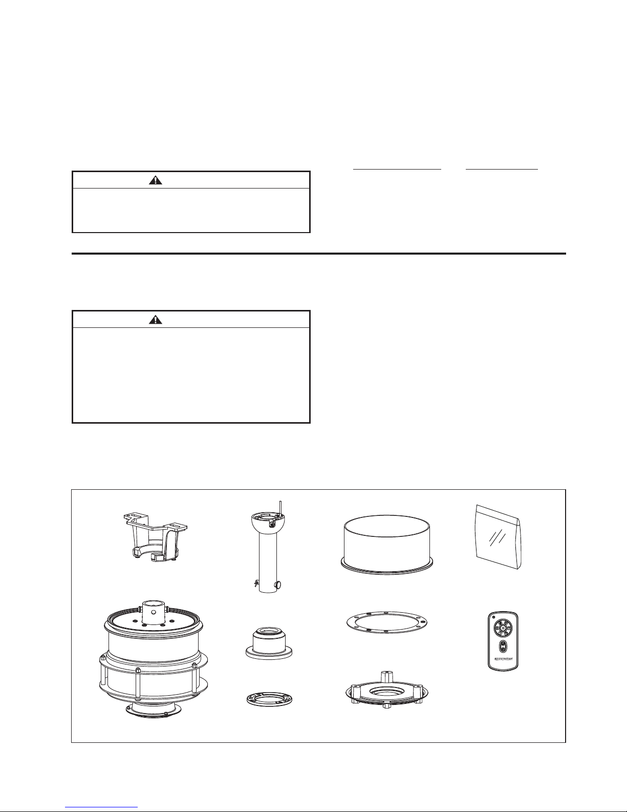
Unpacking Instructions. . . . . . . . . . . . . . . . . . . . . . . . . . . . . . . . . . . . . . . . . .3
.4..............................snaFgnilieCfoesUtneiciffEygrenE
Electrical and Structural Requirements . . . . . . . . . . . . . . . . . . . . . . . . . . . .4
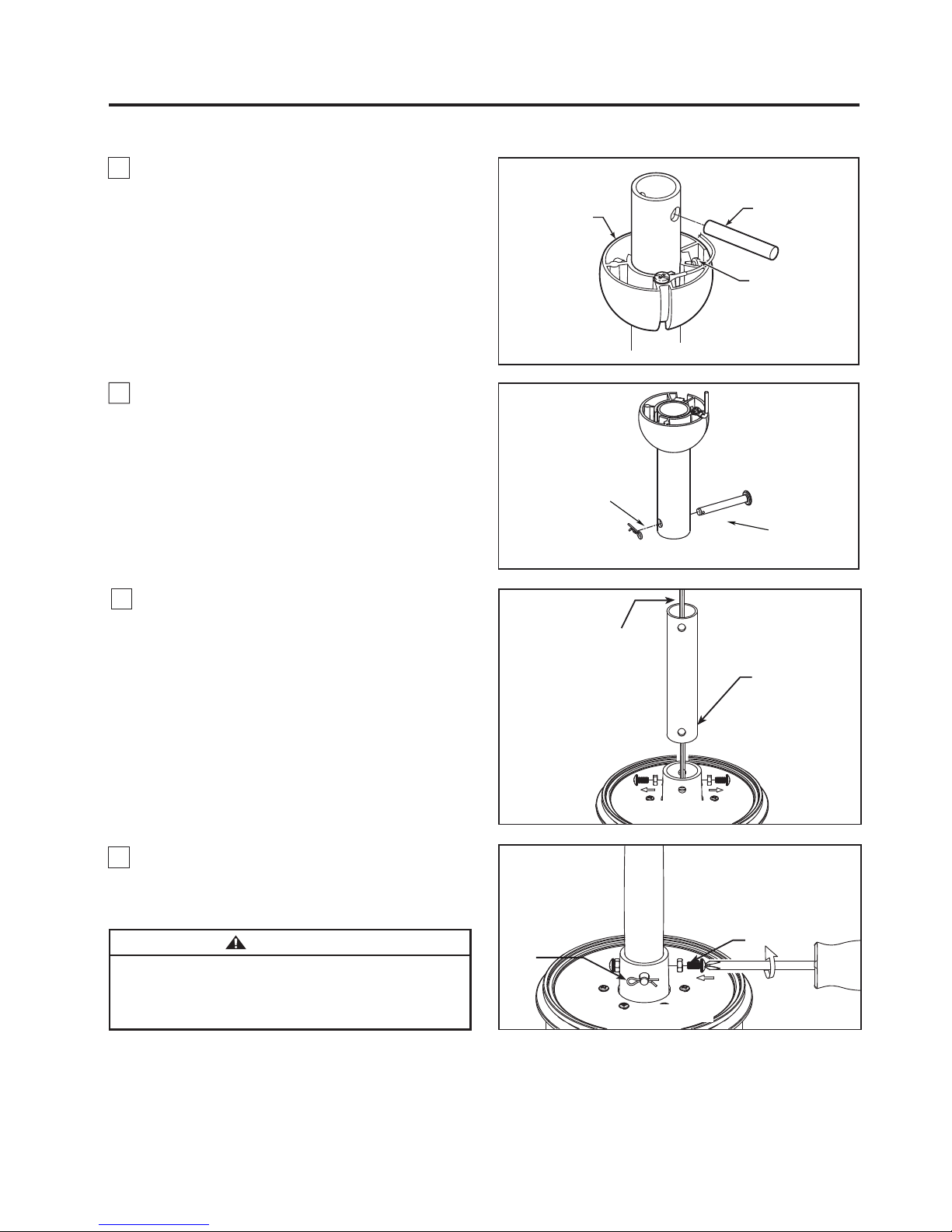
How to Assemble Your Ceiling Fan . . . . . . . . . . . . . . . . . . . . . . . . . . . . . . . .6
How to Hang Your Ceiling Fan . . . . . . . . . . . . . . . . . . . . . . . . . . . . . . . . . . . .8
How to Wire Your Ceiling Fan. . . . . . . . . . . . . . . . . . . . . . . . . . . . . . . . . . . . .9
Installing the Canopy Housing. . . . . . . . . . . . . . . . . . . . . . . . . . . . . . . . . . .10
Assembling the Trim Cover. . . . . . . . . . . . . . . . . . . . . . . . . . . . . . . . . . . . . 10
• These instructions are provided for your safety. It is very important that they are read carefully and completely before beginning the
assembly and installation of this lighting fixture.
• We strongly recommend that a professional electrician install all direct wire fixtures.
• THIS PRODUCT MUST BE INSTALLED IN ACCORDANCE WITH THE APPLICABLE INSTALLATION CODES BY A PERSON
FAMILIAR WITH THE CONSTRUCTION AND OPERATION OF THE PRODUCT AND THE HAZARDS INVOLVED.
• The lighting fixture is meant for indoor use. It must be connected only to 3-wire, single-phase electrical supply systems (provided with
Ground wire or equivalent protection system).
• For your safety, it is strongly recommended that two people install and hang the lighting fixture.
• Light bulb should be centered inside the fixtures shade. Making sure it does not touch the shade sides.
• Save these instructions.
This device complies with Part 15 of the FCC Rules. Operation is subject to the following two conditions:
(1) This device may not cause harmful interference, and (2) this device must accept any interference received, including
interference that may cause undesired operation. If the intentional radiator can be classified as a Class B digital device or a PC
peripheral, then shall include the following or equivalent:
Note: This equipment has been tested and found to comply with the limits for Class B digital device, pursuant to part 15 of the
FCC Rules. These limits are designed to provide reasonable protection against harmful interference in a residential installation.
This equipment generates, uses and can radiate radio frequency energy and, if not installed and used in accordance with the
instructions, may cause harmful interference to radio or television reception, which can be determined by turning the
equipment off and on, the user is encouraged to try to correct the interference by one or more of the following measures:
- Reorient or relocate the receiving antenna.
- Increase the separation between the equipment and the receiver.
- Connect the equipment into an outlet on a circuit different from that to which the receiver is connected.
Consult the dealer or an experienced radio/TV technician for help.
Note: For a Class A digital device, statements of 15. 105(a) must be included when appropriate for the device in question.
WARNING: TO REDUCE THE RISK OF ELECTRIC SHOCK, THIS FAN MUST BE INSTALLED WITH A GENERAL USE,
ISOLATING WALL CONTROL/ SWITCH.
WARNING: This product is designed to use only those parts supplied with this product and/or accessories designated specifically for
use with this product. Using parts and/or accessories not designated for use with this product could result in personal injury or property
damage.
WARNING: To reduce the risk of personal injury, do not bend the blade bracket (flange or blade holder) when installing the brackets,
balancing the blades, or cleaning the fan. Do not insert foreign objects in between rotating fan blades.
7. For supply connections, if the conductor of a fan is identified as a grounded conductor, then it should be connected to a grounded
conductor power supply. If the conductor of a fan is identified as an ungrounded conductor, then it should be connected to an ungrounded
conductor power supply. If the conductor of a fan is identified for equipment grounding, then it should be connected to an
equipment-grounding conductor.
WARNING: To reduce the risk of fire, electric shock, and injury to persons, ceiling-suspended fan, model Peregrine must be
installed with blade and diffuser that are marked on their cartons to indicate the suitability with this model. Other blade and diffuser
cannot be substituted.
• The lighting fixture is for DAMP LOCATIONS.
• Use Only With Light Kits Marked Suitable For Use In DAMP Locations.
• The appliance is not intended for use by young children or infirm persons without supervision. Young children should be supervised to
ensure that they do not play with the appliance.
WARNING: Do not operate this fan with a variable (Rheostat) wall controller or dimmer switch. Doing so could result in damage to the
ceiling fan's remote control unit.
Maintenance. . . . . . . . . . . . . . . . . . . . . . . . . . . . . . . . . . . . . . . . . . . . . . . . . . . .12
How to Clean Your Ceiling Fan Blades . . . . . . . . . . . . . . . . . . . . . . . . . . . . . .12
Falcon Parts List . . . . . . . . . . . . . . . . . . . . . . . . . . . . . . . . . . . . . . . . . . . . . . . .13
Falcon Exploded-View Illustration . . . . . . . . . . . . . . . . . . . . . . . . . . . . . . . . . 14
Light Kit Optional . . . . . . . . . . . . . . . . . . . . . . . . . . . . . . . . . . . . . . . . . . . . . . .15
Fan Blade Optional . . . . . . . . . . . . . . . . . . . . . . . . . . . . . . . . . . . . . . . . . . . . . 15
Trouble Shooting. . . . . . . . . . . . . . . . . . . . . . . . . . . . . . . . . . . . . . . . . . . . . . . .17
Semi Flush Mount Kit Optional . . . . . . . . . . . . . . . . . . . . . . . . . . . . . . . . . . . .16
How to Operate Your Ceiling Fan . . . . . . . . . . . . . . . . . . . . . . . . . . . . . . . . . . 11

This manual is designed to make it as easy as possible for you
to assemble, install, operate, and maintain your Rejuvenation ceiling fan
Unpacking Instructions
For your convenience, check-off each step. As each step is completed, place a check mark. This will ensure that all
.detpurretniebuoydluohsecalpruoygnidnifnilufpleheblliwdnadetelpmocneebevahspets
Wiring outlet box and box connectors must be of type
required by local code. The minimum wire would be a 3-
conductor (2-wire with ground) of the following size:
NOTE: Place the parts from the loose parts bags in a small
container to keep them from being lost. If any parts are missing,
contact Rejuvenation at 888.401.1900
Tools Needed for Assembly Materials
Wire Size A.W.G.Installed Wire Length
14
12
Up to 50 ft.
50 - 100 ft.
NOTE: If you are uncertain of part description, refer to
exploded view illustration.
3
1. Check to see that you have received the following
parts:
Hardware Bag
Fan Motor
Assembly
Downrod/
Hanger Ball Assembly
Ceiling Canopy
Blade Plate
Trim Cover
• One Phillips head screwdriver
• One stepladder
• One ¼” blade screwdriver
• One wire stripper
•Four wire connectors
(supplied)
WARNING
WARNING
Before assembling your ceiling fan, refer to section on
proper method of wiring your fan (page 9). If you feel you
do not have enough wiring knowledge or experience,
have your fan installed by a licensed electrician.
• Fan Motor Assembly
• Hanger Bracket Assembly
• Downrod/Hanger Ball
Assembly
• Ceiling Canopy
• Motor Coupling Cover Assembly
• Blade Plate
• Trim Cover
• Hand Held Remote
• Canopy Screw Cover Assembly
• Hardware bag:
– Seven 1/4˝-20 pan head screws
(blade holder to fan motor hub)
with lockwashers
with lockwashers
– Four #6-32 pan head screws
– Four wire connectors
– Balance Kit
– Phillips screwdriver,4˝
Hanger Bracket
Assembly
Motor Coupling
Cover Assembly
Canopy Screw
Cover Assembly
Hand Held Remote
Do not install or use fan if any part is damaged or
missing. This product is designed to use only those
parts supplied with this product and/or any accessories
designated specifically for use with this product by
Rejuvenation. Substitution of parts or accessories not
designated for use with this product by Fanimation could
result in personal injury or property damage. Contact
Rejuvenation at 888.401.1900 for missing or damaged
parts.

4
Energy Efficient Use of Ceiling Fans
Ceiling fan performance and energy savings rely
heavily on the proper installation and use of the ceiling
fan. Here are a few tips to ensure efficient product
performance.
Choosing the Appropriate Mounting Location
Ceiling fans should be installed, or mounted, in the middle
of the room and at least 7 feet above the floor and 18
inches from the walls. If ceiling height allows, install the fan
8 - 9 feet above the floor for optimal airflow. Consult your
Fanimation Retailer for optional mounting accessories.
Turn Off When Not in the Room
Ceiling fans cool people, not rooms. If the room is
unoccupied, turn off the ceiling fan to save energy.
Using the Ceiling Fan Year Round
Summer Season: Use the ceiling fan in the counter-
clockwise direction. The airflow produced by the ceiling
fan creates a wind-chill effect, making you “feel” cooler.
Select a fan speed that provides a comfortable breeze,
lower speeds consume less energy.
Winter Season: Reverse the motor and operate the ceiling
fan at low speed in the clockwise direction. This produces
a gentle updraft, which forces warm air near the ceiling
down into the occupied space.Remember to adjust your
thermostat when using your ceiling fan - additional energy
and dollar savings could be realized with this simple step!
Electrical and Structural Requirements
Your new ceiling fan will require a grounded electrical
supply line of 120 volts AC, 60 HZ, 15 Amp Circuit.
Electrical code requires use of a fan-rated outlet box to
support the extra weight and motion associated with a
ceiling fan. A fan-rated box will be labeled as such and
typically supports up to a 70lb ceiling fan. Fan-Rated
Outlet Boxes vary in ratings and design. Ensure the
ratings of your ceiling fan outlet box meet the
requirements for the ceiling fan being installed. Figure 1,
Figure 2 and Figure 3 depicts different structural
configurations that may be used for mounting the
outlet box.
Low profile usage diagram idea (Figure 1)
A 1⁄2-in.-deep pancake box is meant to be screwed to a
joist or block. It’s used if only one cable is coming into
the box. It is also available in a saddle-mount
configuration.
CEILING
2" x 4"
CEILING JOIST
OUTLET BOX
Figure 1
Figure 2
2" x 4"
CEILING JOIST
CEILING OUTLET BOX
Deeper profile usage diagram idea (Figure 2)
A 2-1⁄4-in.-deep box can be attached to blocking
between joists and is roomy enough to handle more
than one cable.

5
Electrical and Structural Requirements (Continued)
If your fan is to replace an existing light fixture, turn
electricity off at the main fuse box at this time and
remove the existing light fixture.
Turning off wall switch is not sufficient. To avoid
possible electrical shock, be sure electricity is
turned off at the main fuse box before wiring. All
wiring must be in accordance with National and
Local codes and the ceiling fan must be properly
grounded as a precaution against possible electrical
shock.
WARNING
WARNING
Deep box with brace (Figure 3)
Paired with a deep box, this hanger is meant to span
between two joists and takes the place of wooden
blocking.
To avoid fire or shock, follow all wiring instructions
carefully. Any electrical work not described in these
instructions should be done or approved by a
licensed electrician.
WARNING
Figure 3
CEILING JOIST
CEILING
OUTLET BOX
To reduce the risk of fire, electric shock, or personal
injury, mount to outlet box marked acceptable for fan
support of 15.9 kg (35 lbs) or less and use mounting
screws provided with the outlet box. Most outlet boxes
commonly used for the support of luminaires are not
acceptable for fan support and may need to be
replaced, consult a qualified electrician if in doubt.
Do not operate this fan with a variable (Rheostat) wall
controller or dimmer switch. Doing so could result in
damage to the ceiling fan's remote control unit.
WARNING

6
How to Assemble Your Ceiling Fan
Figure 1
Pin
Setscrew
Hanger
Ball
1. Prior to assembly, set aside and save the hardware
bags packed in the packing. Remove the hanger ball
by loosening the setscrew in the hanger ball until the
ball falls freely down the downrod. Remove the pin
from the downrod, then remove the hanger ball.
Retain the pin and hanger ball for reinstallation in
Step 6. (Figure1)
4. Install the clevis pin, hairpin clip and tighten set
screws. The clevis pin and hair pin clip must be
properly installed to prevent the set screws from
working loose. (Figure 4)
WARNING
It is critical that the clevis screw in the downrod support is
properly installed and the setscrews and nuts are securely
tightened. Failure to verify that the clevis screw, nuts, hairpin
clip and setscrews are properly installed could result in the fan
falling.
2. Remove the hairpin clip and clevis pin from the
bottom of downrod. Retain the pin and clip for
reinstallation in Step 4. (Figure 2)
Hairpin
Clip
Clevis Pin
Figure 2
3. The fan comes with black and white wires.
Separate and untwist the two wires route them through
the downrod. Loosen the two setscrews in the downrod
support. Install downdrod into coupler. Align the clevis
pin holes in the downrod with the holes in the downrod
support. (Figure 3)
Hairpin
Clip
Set Screw
w/Hex Nut
Downrod Support
Black and White wires
Figure 3
Figure 4

5. Route wires through motor coupling cover,
7
How to Assemble Your Ceiling Fan (continued)
5.
canopy screw cover and ceiling canopy. (Figure 5)
7. Cut off excess lead wire approximately 6 to 9
inches above top of the top of the downrod. Strip
1/2 inch from the end of each leadinsulation off
wire. (Figure 7)
NOTE:
All set screws must be checked, and retightened
where necessary, before installation.
Canopy Screw
Cover
Ceiling
Canopy
Motor
Coupling
Cover
Figure 5
Figure 6
Figure 7
x 6
1/4˝-20
SCREWS
HARDWARE USED:
Figure 8
Blade Plate
Motor
Assembly
(2 each per blade) Blade
(not included)
8. Secure the three blades using the 1/4˝-20 screws
with blade plate through the holes located on the
bottom of the motor assembly (marked A-A, B-B, C-C).
(Figure 8)
NOTE: You will find the fan blade set packed in its own
carton and hardware bag in the fan box.
6. Reinstall the hanger ball on the downrod as
follows. Route the two 80 in. wires through the hanger
ball. Position the pin through the two holes in the
downrod and align the hanger ball so the pin is
captured in the groove in the top of the hanger ball.
Pull the hanger ball up tight against the pin. Securely
tighten the set screw in the hanger ball. A loose set
screw could create fan wobble. (Figure 6)
1/4˝-20 Screw
w/Lock Washer

8
How to Hang Your Ceiling Fan
Figure 1
MAIN FUSE BOX
Figure 4
Figure 3
Outlet Box
Hanger
Bracket
Outlet Box
Hanger
Bracket
Screw (2)
Supplied with
Outlet Box
Tab
Downrod/Hanger
Ball Assembly
Figure 2
Floor
Ceiling
No
less than
7 ft
NOTE: If you are not sure if the outlet box is grounded,
contact a licensed electrician for advise, as it must be
grounded for safe operation.
WARNING
The fan must be hung with at least 7’ of clearance
from floor to blades. (Figure 2)
2. Carefully lift the fan and seat the downrod/hanger ball
assembly on the hanger bracket that was just attached
to the outlet box. Be sure the groove in the ball is lined
up with tab on the hanger bracket. (Figure 4)
WARNING
Failure to seat tab in groove could cause damage to
electrical wires and possible shock or fire hazard.
WARNING
To avoid possible shock, do not pinch wires between
the hanger ball assembly and the hanger bracket.
1. Securely attach the hanger bracket to the outlet box
using the outlet box screws and washers supplied with
the outlet box. (Figure 3)
WARNING
The outlet box must be securely anchored. Hanger
bracket must seat firmly against outlet box. If the
outlet box is recessed, remove wall board until bracket
contacts box. If bracket and /or outlet box are not
securely attached, the fan could wobble or fall.
WARNING
To avoid possible fire or shock, be sure electricity is
turned off at the main fuse box before hanging.
(Figure 1)
Flat Washer

9
How to Wire Your Ceiling Fan
To avoid possible electrical shock, be sure electricity
is turned off at the main fuse box before hanging
(Figure 1).
WARNING
MAIN FUSE BOX
Figure 1
NOTE:
If you are not sure if the outlet box is
grounded, contact a licensed electrician for advice, as
it must be grounded for safe operation.
Figure 2
1. Connect the green grounding lead from the
downrod/hanger ball assembly and the green
grounding lead from the hanger bracket to the supply
grounding conductor (this may be a bare wire or wire
with green colored insulation). Securely connect wires
with wire connector. Securely connect the white fan
motor wire to the white supply (neutral) wire using
wire connector. Securely connect the black fan motor
wire to the black supply wire using wire connector
(Figure 2).
Green Wire
from Supply
(Ground) White Wire
from Supply
White Wire
from Fan
Green Wire
from Hanger
Bracket (Ground)
Green Wire
from Hanger
Ball (Ground)
Listed
Outlet Box
Household
Supply
Black Wire
from Supply
Black Wire
from Fan
x 3WIRE
CONNECTORS
HARDWARE USED:
NOTE:
If you feel that you do not have enough electrical
wiring knowledge or experience, have your fan installed
by a licensed electrician.
Check to see that all connections are tight, including
ground, and that no bare wire is visible at the wire
connectors except for the ground wire. Do not
operate fan until the blades are in place. Noise and
motor damage could result.
WARNING
Figure 3
Green Wire
from Supply
(Ground) White Wire
from Supply
White Wire
from Fan
Green Wire
from Hanger
Bracket (Ground)
Green Wire
from Hanger
Ball (Ground)
Listed
Outlet Box
Household
Supply
Black Wire
from Supply
Black Wire
from Fan
2. After connections have been made, turn leads
upward and carefully push leads into the outlet
box, with the white and green leads to one side
of the box and the black leads toward the
other side. The wires should be spread apart
with the grounded conductor and the
equipment-grounding conductor on one side of
the outlet box and the ungrounded conductor
on the other side of the outlet box. (Figure 3)

1. Position the trim cover onto the blade plate
bottom using #6-32 screws. (Figure 1)
Figure 1b
10
Installing the Canopy Housing
Figure 1a
NOTE: This step is applicable after the necessary wiring
is completed.
WARNING
To avoid possible fire or shock, make sure that the
electrical wires are completely inside the canopy housing
and not pinched between the housing and the ceiling.
2. Securely attach and tighten the canopy screw
cover over the shoulder screws in the hanger
bracket utilizing the keyslot twist-lock feature
(Figure 1b).
1. Remove one of the two shoulder screws in the
hanger bracket. Loosen the second shoulder screw
without fully removing it. Assemble canopy by
rotating key slot in canopy over shoulder screw in
hanger bracket. Tighten shoulder screw. Fully
assemble and tighten second shoulder screw that
was previously removed (Figure 1a).
Assembling the Trim Cover
x 3
#6-32
SCREWS
HARDWARE USED:
Blade
Blade Plate
Figure 1
#6-32
Pan Head Screw
w/Lock Washer
Trim Cover

For illustrative purposes only-not
intended to cover all types of controls
11
How to Operate Your Ceiling Fan
MAIN FUSE BOX
Figure 2
Figure 1
Figure 3
2. Restore electrical power to the outlet box by turning
the electricity on at the main fuse box (Figure 2).
1. IMPORTANT: Using a full range dimmer switch
(not included) to control fan speed will damage the fan.
To reduce the risk of fire or electrical shock, do not use
a full range dimmer switch to control the fan speed.
(Figure 1)
Check to see that all connections are tight, including
ground, and that no bare wire is visible at the wire
connectors, except for the ground wire. Do not
operate fan until the blades are in place. Noise and
fan damage could result.
WARNING
NOTE:
There are no frequency switches on the receiver
unit. The receiver will automatically scan the frequency
from the hand held control if any changes are made.
The frequency settings should only be changed in the
case of interference or if multiple ceiling fans with the
same type of control system are installed in the same
structure.
3. To make fan operational, install 23A/12V battery
(included) in hand-held remote transmitter, with fan
power off. Within 60 seconds of restoring power to the
fan, press and hold the “SET” button for 3-5 seconds to
set the code in the receiver. The ceiling fan lights
(if installed) will flash to indicate the remote code has
been paired with the receiver. (If not used for long
periods of time, remove battery to prevent damage to
transmitter). Store the remote away from excessive
heat or humidly (Figure 3).
Figure 4
4. The remote buttons instruct as below:
I = minimum speed II = low speed
III = medium low speed IV = medium speed
V = medium high speed VI = high speed
: Turns the fan off.
: Controls fan direction - forward and reverse.
: Controls light-Infinite light levels are available by
holding the light on/off button (Figure 4).
Fan speed:
NOTE: The light kit is optional, not included in the fan box.
WARNING
Do not operate this fan with a variable (Rheostat) wall
controller or dimmer switch. Doing so could result in
damage to the ceiling fan's remote control unit.

Maintenance
How to Clean Your Ceiling Fan Blades
1. ylnoehtsinafgniliecwenruoyfogninaelccidoireP
maintenance that is needed.
When cleaning, use only a soft brush or lint free cloth
.hsinifehtgnihctarcsdiovaot
Abrasive cleaning agents are not required and should
be avoided to prevent damage to finish.
Periodic light dusting of the blades is recommended.
A feather duster will work best.
Avoid using water, cleansers, or harsh rags, which can
warp and ruin the blades.
CAUTION
Do not use solvents when cleaning your ceiling fan. It
could damage the motor or the blades and create the
possibility of electrical shock.
RECOMENDED: Periodically check that the blade holders to motor hub screws are secure and tight.
How to Operate Your Ceiling Fan (continued)
Figure 5
5. “D” and “ON” dip switch:
For this fan, switch should be in the "ON" position, allowing
for dimming of the light. (Figure 5)
The receiver provides the following protective function:
Lock position: The DC motor has a built-in safety feature
against blade obstruction against obstruction during
operation. If something obstructs the fan blades the motor
will stop operating after 30 seconds of interruption. Please
remove obstacles and reset.
Over 80W protection: When the receiver detects motor
power consumption which is greater than 80W, the
receiver power will shutdown and fan operation will cease.
Disconnect the power supply and after 5 seconds return-
power on to the fan.
12

13
Before discarding packaging materials, be certain all parts have been removed
How To Order Parts
When ordering repair parts, always
give the following information:
• Part Number
• Part Description
• Fan Model Number
Contact Rejuvenation at 888.401.1900
for repair parts.
Falcon Parts List
2Downrod/Hanger Ball Assembly
3 Ceiling Canopy
1 Hanger Bracket Assembly
Canopy Screw Cover Assembly4
Motor Coupler Cover Assembly5
6
7
Trim Cover8
9
10
ADRAC1-45**
P799001**
APP799004BL
APPCP1101**
AP799002**
Blade Plate P799008BL
Fan Motor Assembly AMA7990**
P799005**
Ref.# Description Part #
Hardware Bag Containing:
HDWMAD7990**
Balance Kit (BALKT)
Wire Connectors (4)
#6-32 Pan Head Screws, with Lock Washer (4)
Blade Mounting Hardware Bag Containing:
1/4˝-20 Pan Head Screws, with Lock Washer (7)
Phillips screwdriver,4˝
11
TR39RJ
RC165M-7990SO
Hand Held Remote
Receiver

Exploded-View
Illustration
14
Falcon
9
11
1
2
3
4
5
NOTE: The illustration shown is not to scale or its actua
™
6
7
8
10

Light Kit Optional
Model # A0245, A0386
Fan Blade Optional
Model # A0241, A0242 & A0243
Light Plate Asssembly1
2
3
LED Plate Assembly
Light Screw Cover Assembly
AP799013BL
AP799016**
AP799014**
Blade Set1 A0241, A0242, A0243
15
1
Before discarding packaging materials, be certain all parts have been removed
How To Order Parts
When ordering repair parts, always
give the following information:
• Part Number
• Part Description
• Fan Model Number
Contact Rejuvenation at 888.401.1900
repair parts.
NOTE: ion may vary.
2
3

Semi Flush Mount Kit Optional
Model # A0249, A0387
Ceiling Bracket Asssembly
Motor Coupler Washer
1
2
AP799009BL
PPCP1702BL
3
4
Canopy
Canopy Trim Ring Assembly AP799010**
P799012**
16
1
Before discarding packaging materials, be certain all parts have been removed
How To Order Parts
When ordering repair parts, always
give the following information:
• Part Number
• Part Description
• Fan Model Number
Contact Rejuvenation at 888.401.1900
repair parts.
NOTE: ion may vary.
2
3
4

17
Trouble Shooting
Trouble Probable Cause Suggested Remedy
1. FAN WILL NOT START 1. Fuse or circuit breaker blown.
2. Loose power line connections to the fan, or loose
switch wire connections in the switch housing.
1. Check main and branch circuit fuses or circuit
breakers.
2. Check line wire connections to fan and switch wire
connections in the switch housings.
CAUTION: Make sure main power is turned off !
3. Replace with fresh battery.
2. FAN SOUNDS NOISY 1. Blades not attached to fan.
2. Loose screws in motor housing.
3. Screws securing fan blade holders to motor hub are
loose.
4. Wire connectors inside housing rattling.
5. Motor noise caused by solid state variable speed
control.
1. Attach blades to fan before operating.
2. Check to make sure all screws in motor housing are
snug (not over-tight).
3. Check to make sure the screws which attach the fan
blade holders to the motor hub are tight.
4. Check to make sure wire connectors in switch
housing are not rattling against each other or against
the interior wall of the switch housing.
CAUTION: Make sure main power is turned off !
5. Some fan motors are sensitive to signals from
solid-state variable speed controls. Solid-state controls
are not recommended, choose an alternative control
method.
3. FAN WOBBLES
EXCESSIVELY
1. Setscrew and nut in downrod support is loose.
2. Setscrew in downrod/hanger ball assembly is loose.
3. Blade holders or blade plate not seated properly.
4. Hanger bracket and/or ceiling outlet box is not
securely fastened.
5. Fan blades out of balance.
1. Tighten both setscrews and nuts securely in downrod
support.
2. Tighten the setscrew in the downrod/hanger ball
assembly.
3. Check to be sure the fan blade and blade plate
seat firmly and uniformly to the surface of the motor
housing. If blade or blade plate are seated incorrectly,
loosen the screws and retighten.
4. Tighten the hanger bracket screws to the outlet box,
and secure outlet box.
5. Interchanging position of fan blades can redistribute
the weight and result in a smoother operation. For
example, exchange blades in positions 1 and 3 or 1 and
4. If this does not improve wobble, exchange 2 and 4.
4. NOT ENOUGH AIR
MOVEMENT
1. If possible, consider using a longer downrod
(not included, you can buy the longer downrod from
rejuvenation.com).
WARNING
For your own safety turn off power at fuse box or circuit breaker before trouble shooting your fan.
3. Dead battery in remote control.

2550 N.W. Nicolai Street, Portland Oregon 97210
Customer Service: 888-401-1900
www.rejuvenation.com

Peso neto 5,87 kg (12.93 lb)
Ventilador de techo
MANUAL DEL PROPIETARIO
LEA Y GUARDE ESTAS INSTRUCCIONES
™
The Falcon

Tabla de contenidos
Instrucciones de seguridad importantes
ADVERTENCIA: Siga estas instrucciones para prevenir incendios, descargas eléctricas y lesiones personales graves.
Instrucciones de seguridad adicionales
Para evitar posibles descargas eléctricas, asegúrese de que la electricidad esté desconectada en la caja de fusibles antes de realizar1.
la instalación eléctrica, y no haga funcionar el ventilador sin las aspas.
Todos los procedimientos de conexión eléctrica e instalación deben cumplir con los Códigos eléctricos nacionales (ANSI/NFPA2.
70-1999) y Códigos locales. El ventilador de techo debe estar conectado a tierra a fin de prevenir posibles descargas eléctricas. La
instalación eléctrica debe ser llevada a cabo o aprobada por un electricista autorizado.
Se debe fijar bien la base del ventilador; ésta debe ser capaz de soportar sin problemas al menos 15,9 kg (35 lb). Si tiene dudas,
consulte a un electricista calificado.
3.
Las aspas del ventilador deben instalarse por lo menos a 2 m (7 pies) del suelo, a fin de evitar un contacto accidental con la s mismas.4.
Siga las recomendaciones sobre el método correcto de instalación eléctrica de su ventilador de techo. Si no posee la experiencia o5.
los conocimientos eléctricos adecuados, contrate a un electricista autorizado para instalar el ventilador.
6. Apto para usar con controles de velocidad de estado sólido.
ADVERTENCIA: PARA REDUCIR EL RIESGO DE DESCARGAS ELÉCTRICAS, ESTE VENTILADOR SE DEBE INSTALAR CON UN
CONTROL/INTERRUPTOR DE PARED AISLADO.
ADVERTENCIA: Este producto está diseñado para ser usado sólo con las piezas suministradas o los accesorios indicados
específicamente para el mismo. Si utiliza piezas o accesorios que no están indicados para su uso con este producto, podría
sufrir lesiones personales o dañar el ventilador. ADVERTENCIA: Este producto está diseñado para ser usado sólo con las piezas
suministradas o los accesorios indicados específicamente para el mismo. Si utiliza piezas o accesorios que no están indicados para su
uso con este producto, podría sufrir lesiones personales o dañar el ventilador.
ADVERTENCIA: P
ADVERTENCIA: Para reducir el riesgo de incendio, descarga eléctrica y heridas personales, el ventilador suspendido en el techo
(modelo Peregrine) debe ser instalado con las palas y el difusor que vengan marcados en sus cajas como apropiados para este modelo.
No pueden utilizarse otras palas o difusores.
ara reducir el riesgo de lesiones personales, no doble los soportes de las aspas (borde o soporte de aspas) al instalar
los soportes, balancear las aspas o limpiar el ventilador. No coloque objetos extraños entre las aspas del ventilador en funcionamiento.
l
(1) Este equipo no causará interferencias perjudiciales y (2) este equipo tolerará cualquier interferencia recibida, incluidas las
interferencias que puedan provocar un funcionamiento no deseado. Si el radiador intencional puede ser clasificado como un
dispositivo digital de clase B o un periférico del ordenador, entonces se deberán incluir los siguientes o equivalentes:
Nota: Tras someterlo a las pruebas correspondientes, se ha determinado que este equipo cumple con los límites establecidos para
dispositivos digitales de Clase B de conformidad con la parte 15 de la Normativa FCC. Estos límites se han establecido con el objetivo
de aportar una protección razonable contra interferencias perjudiciales cuando el equipo se utiliza en el hogar. Este equipo genera,
utiliza y puede emitir energía de radiofrecuencia y, a menos que se instale y se utilice de acuerdo con el manual de instrucciones, puede
provocar interferencias perjudiciales en las comunicaciones por radio y televisión. Si el equipo produce interferencias perjudiciales en la
recepción de radio o televisión, lo cual puede probarse encendiendo y apagando el equipo, se recomienda al usuario corregir dichas
interferencias tomando una o varias de las siguientes medidas:
- Modificar la orientación o ubicación de la antena de recepción;
- Aumentar la separación entre el equipo y el receptor;
- Conectar el equipo a una toma de corriente o circuito diferente al del receptor;
Consulte al distribuidor o a un técnico especialista de radio o TV para obtener más ayuda.
Nota: Para un dispositivo digital de clase A, la declaración de 15. 105(a) debe ser incluida cuando sea apropiada para el dispositivo en
cuestión.
7. En lo que respecta a las conexiones de suministro, si el conductor del ventilador está identificado como conductor con conexión a tierra,
se le debe conectar a un suministro de electricidad con conductor de puesta a tierra. Si el conductor del ventilador está identificado
como conductor que no es de puesta a tierra, se le debe conectar a un suministro de electricidad con conductor sin puesta a tierra.
Si el conductor del ventilador está identificado para equipos de puesta a tierra, se le debe conectar al conductor de equipos de puesta
a tierra.
• Estas instrucciones se ofrecen por su seguridad. Es muy importante que se lean completa y minuciosamente antes de comenzar la
instalación de este dispositivo de iluminación.
• Le recomendamos que un electricista profesional instale todos los dispositivos eléctricos.
• ESTE PRODUCTO DEBE SER INSTALADO SEGÚN LAS REGULACIONES DE INSTALACIÓN APLICABLES POR UNA PERSONA
QUE ESTÉ FAMILIARIZADA CON LA CONSTRUCCIÓN Y EL FUNCIONAMIENTO DEL PRODUCTO Y DE TODOS LOS PELIGROS QUE
CONLLEVA.
• El dispositivo de iluminación ha sido diseñado para su uso en interiores. Solo debe conectarse a sistema de suministro eléctrico de fase
simple y tres cables (suministrado con un cable de toma de tierra o un sistema de protección equivalente).
• Por su seguridad, se recomienda que dos personas instalen y sostenga el dispositivo de iluminación.
• Las bombillas de iluminación deberían centrarse dentro de la pantalla de la iluminación del dispositivo. Asegúrese de no tocar los
laterales de la pantalla.
• Guarde estas instrucciones.
• El dispositivo no ha sido diseñado para ser utilizado por niños pequeños o personas enfermas sin supervisión. Los niños pequeños deben
ser supervisados para evitar que jueguen con el dispositivo.
Instrucciones para el desempaque.................................
.............................
..................
Requisitos eléctricos y estructurales...............................
................................
. ... . . . ...o
cetedrodalitneledacirtcélenóicalatsnialrazilaeromóC
Ensamblaje de la carcasa decorada ...............................
............................
21
22
22
24
26
27
28
28
.......................................
...............................
...............
...............
...............
Mantenimiento
................................
..................................................
.....................
.........................
.........................
Solución de problemas ............................
Lista de piezas de Falcon . .
Ilustración del despiece de Falcon . . .
Cómo limpiar las palas de su ventilador de techo
Kit de iluminación opcional
Pala de ventilador opcional
Kit opcional de montaje semi flush .................................
29
30
30
31
32
33
33
34
35
• El dispositivo de iluminación ha sido diseñado exclusivamente para en ubicaciones con humedad.
• Utilice el producto solo con los kits de iluminación marcados como adecuados para el uso en ubicaciones con humedad.
ADVERTENCIA: No utilice este ventilador con un controlador variable de pared (Rheostat) o un regulador de intensidad. Si lo hiciera
podría dañar la unidad del mando a distancia del ventilador de techo.
Table of contents
Languages:
Other Rejuvenation Fan manuals
Popular Fan manuals by other brands

Argo
Argo Polifemo BREEZE operating instructions

Vents
Vents P2-1-300 Installation and Operation Guidelines

Elta
Elta Compact SCP Installation and maintenance instructions

Broan
Broan VENTILLATION FAN QTR100 instructions

Attic Breeze
Attic Breeze AB–2062 installation guide

Luma
Luma Comfort MF18W owner's manual

NuAire
NuAire MRXBOXAB-ECO2-AESW installation manual

Maico
Maico ECA piano STANDARD Mounting and operating instructions

Helios
Helios ecovent KWL 45 WS Installation and operating instructions

Vallox
Vallox 75 Instructions for use and maintenance

INNOLIVING
INNOLIVING INN-503 user manual

ORIGO
ORIGO DF-1201 instruction manual