lavenergi SYSTEMER LUNOS User manual

1
NO Monteringsanvisning
ventilatorinsats Silvento ec
- Videreleveres til beboer/eier -
EN Installation Manual
Fan Insert Silvento ec
- Please pass on to user -
E169 NO 02.21 v.08
2
1
2
3
4
NO Tips 2
EN Hints 2
5
NO Leveranseinnhold 3
EN Delivery units 3
NO ontasje 3
EN Assembly 3
NO Elektrisk tilkobling 5
EN Elektrical connection 5
NO Filtervedlikehold 5
EN Filter replacement 5
6 NO Tekstdel / Beskrivelse 6
EN Text part / description 13
2,25 m
1 1
0
2
1 2
0

3
040078
V-EC
2
(E)
(D)
3.3
(B)
3.2
3 (A)
3.1
4
(G)
(D)
(F)
3.4
3.5
3.7
3.8
3.6
(Q)
90°
90°

5
4.1 4.2
4.3
(R)
4.4
(R)
5/W
LED
4.5
4
TAC
5/W2
3 s
(S)
5
6
Innhol : Si e:
Om denne anvisningen, sikkerhetsanvisninger, driftsområde, avhending 6
Tekniske Data, tips 7
ontasje - Ventilatorinnsats, styrekort og innvendig deksel 8
ontasje - tilleggsmoduler 8
Elektrisk tilkobling 9
Innstilling av DIP-brytere 10
Beskrivelse av fuktighetsstyring 11
Filtervedlikehold, rengjøring, tilleggs og byttedeler 12
Les denne veiledningen i sin helhet før motering påbegynnes! Følg alltid de generelle
sikkerhetsrådene og henvisninger til symboler med notater i teksten.
Denne veiledningen skal overleveres til brukeren (leietaker, eier, eiendomsforvalter, etc.) etter at
installasjonen er sluttført.
Symboler i enne veile ningen:
Dette symbolet advarer om fare for skade.
Dette symbolet advarer om fare for skade fra elektrisk strøm
Advarsel! Ved alt montasjearbeide på ventilasjonsutstyret skal nettspenning være frakoblet,
OBS! Elektrisk tilkobling til nettspenning, (220 Volt AC), skal gjøres av autorisert personell, I
henhoold til gjeldende forskrifter.
OBS! Utstyret skal ikke betjenes (eks. filterbytte, renhold) av barn eller personer som
grunnet fysisk, sensorisk eller mentale evner, uerfarenhet eller uvitenhet, ikke er i stand til å
betjene utstyret på en sikker måte.
Til ventilatorer for avtrekk må det alltid sørges for at det finnes tilluft tilgjengelig utenfra.
Temperaturområde: - 15°C til + 40°C
Anvendelig ved relativ luftfuktighet til 75% innendørs, (ikke kondenserende, kortvarige overskridelser
med ventilator i drift tillates). Ved overskridelse kobles apparatet ut. Tilfør friskluft ved lufting gjennom
vindu.
Husk å kildesortere emballasjeavfallet.
Følg lokalt regelverk for kildesortering og elektronisk avfall ved avhending.
Monteringsanvisning NO
Om enne anvisningen
Sikkerhetsanvisninger
Driftsområ e
Avhen ing
6

7
Styrekort 5/EC-KE for kjelleravtrekk er ikke med i oversikten, men informasjonen er tilgjengelig på
forespørsel.
Alle ventilatorer er utstyrt med filter i klasse G2 og LED-varsling for filtervedlikehold.
Ventilatorer I produktserie „Silvento“ tilfredstiller alle krav:
- ifølge DIN 18017-3
- for ‘Lavspenning (CE)‘ ifølge EU retningslinjer (2006/95/EU; 2014/35/EU)
- for elektromagnetisk kompatibilitet (CE) etter EU retningslinjer (2004/108/EU; 2014/30/EU)
Tekniske ata
Spenningstilførsel: 200-240 V AC 50/60 Hz
Styringsinngang: 0-10 V DC
Beskyttelsesklasse: II
Kapslingsgrad: IPX5
Luftmengder: Av, 15-60/90* m³/h
Elektrisk effektbehov: 1,8-6,2/14,5* W
Lydtrykknivå: 22– 35/44* dB(A)
(tilnærmet trinnløs fra 15 til 60/90* m³/h)
*Avhengig av styrekort
Funksjon / Styrekort 5/EC-ZI 5/EC-FK 5/EC-ZI 90 5/-EC-FK 90
Innstilbare luftmengder for
grunnavtrekk (DIP 1,2)
Innstilbare luftmengder for
behovsavtrekk (DIP 6,7)
Innkoblingssforsinkelse (-/45/120s) (/ / ) (/ / ) (/ / ) (/ / )
Forsinket utkobling (-/15/30 min) (/ / ) (/ / ) (/ / ) (/ / )
Intervalldrift
(-/4h30min /2h15min) (/ / ) (/ / ) (/ / ) (/ / )
Automatikk (fuktighet/temperatur) ( - / -) (/ ) ( - / -) (/ )
LED for varsel om filtervedlikehold
Lavspennings inngang 0-10 V
Logging av data
Tillegg: Radiomodul F -EO - eller -
Bevegelsesdetektor 5/B (/ ) (/ ) (/ ) (/ )
15/20/30/40/45/45/50/60 m³/h 15/20/30/40/45/45/50/60/90 m³/h
15/20/30/40/45/45/50/60 m³/h
15/20/30/40/45/45/50/60 m³/h
Alle Silvento ec kan kombineres med styrekort uten fuktsensor eller med fuktsensor. Alle styrekort
kan utstyres med en utvidelsesmodul.
Dette gir følgende konfigurasjonsmuligheter:
ontasje i sone 1 og 2 i bade– og våtrom tilates i henhold til VDE 100.
Ventilatoren kan ikke benyttes for avtrekkshette i kjøkken
1 Tips
8
Forsiktig! Alt monteringsarbeide for ventilasjonssystemet skal kun gjøres ved allpolig frakoblet
nettspenning! Tillegg av installasjoner og elektriske komponenter i dette ventilasjonssystemet
tillates ikke.
3.1 Eventuelle beskyttesesdeksler fjernes fra kapslingen.
Kontrollér elektriske tilkoblinger og posisjonen for tilkoblingskontakt (A)
3.2 Ventilatorinsatsen klikkes på plass og nettilkoblingen skrus fast (B).
3.3 Styrekort (E) settes på plass I filterrammen (D) og skrus fast.
3.4 Styrekortet tilkobles ventilatorinnsatsen med båmdkabelen.
Påse at båndkabelen forlegges riktig.
3.5 Skrueutsparinger (F) åpnes i henhold til benyttet kabinettype.(UP,AP, KL).
Filterrammen (D) skrus fast I kabinettet med de leverte skruer befestigen.
Sett på plass filteret, og klikk på plass innvendig deksel (G).
Bemerk: Filterrammen monteres allti I samsvar me montasjeretningen for vifteinnsatsen.
Innven ig eksel kan så valgfritt settes i to posisjoner på filterrammen, eventuelt reiet 180°.
3.6 Ved bruk av to-romstilkobling legges en fordelingsingsplate (Q) under filteret for å regulere
fordeling av luftmengder. Fordelingsplaten er en del av leveransen av to-roms
montasjesettet.
3 Montasje - Ventilatorinnsats, styrekort og innven ig eksel
3 Montasje - Tilleggsmo uler
Funksjonsutvidelser er tilgjengelig med tilleggsmodulene Bevegelsesdetektor 5/BM (40082) eller
trådløs Radiomodul FM-EO (40083) for kommunikasjon med andre ventilatorer eller via
smarthussentral. odul for funksjonsutvidelse kan settes inn som beskrevet nedenfor:
3.7 Styrekortet (E) løsnes fra filterrammen (D). Tilleggsmodulen settes inn i 6-pins kontakten
under styrekortet, som vist I illustrasjonen. Styrekortet settes tilbake I filterrammen og festes
som angitt i punkt 3.3
3.8 Vertikal og horisontal dekningsområde for Bevegelsesdetektoren er 90°.
NB: Ve tilkobling av nettspenning til fer igmontert ventilator vil
lys io e på styrekortet blinke én gang.

9
Tilleggsinstallasjoner og elektriske komponenter i ventilatorenhet tillates ikke!
Koblingsskjema for ytterligere ventilatorfunksjoner på forespørsel.
Advarsel! Ved alt montasjearbeide på ventilasjonsutstyret skal nettspenning være frakoblet,
Ventilasjonsutstyret er elektrisk isolert i beskyttelsesklasse II, (Kl.II) , beskyttelsesjord er ikke
påkrevet.
Før tilkobling av ventilatorenheten skal alle tilkoblingsledere gjøres spenningsløse.
(Frakobles nettspenning med minimum 3 mm kontaktåpning, for eksempel elektirsk sikring)
All strømtilførsel til ventilatorenhetene skal være beskyttet mot jordfeil, for eksempel med en
jordfeilbryter.
Tilkobling til nettspenning skal kun gjøres av autorisert personell.
4 Elektrisk tilkobling
4.1 Automatisk drift med fuktighetsstyring/grunnavtrekk I henhold til innstilling av DIP-brytere
på styrekortet.
Komfort styringskort: Fuktighetsstyrt drift.
Basis styringskort: Intervallstyring mulig
4.2 ed fjernstyring (0 - 10 V)Fjernstyringsinngangen er delt I to områder. I område 0 - 5 V
settes trinnet absolutt, d.v.s. med høyeste prioritet (tilsvarende DIP-bryter 6,7 med L1
tilkoblet). I område 6 - 10 V blir bare grunnavtrekk satt (tilsvarende DIP-bryter 1,2).
I område 0-0,4 V går ventilatoren uavhengig.
Trinn 0: 0,6 V - 0,9 V
Trinn 1: 1,1 V - 1,4 V
Trinn 2: 1,6 V - 1,9 V
Trinn 3: 2,1 V - 2,4 V
Trinn 4: 2,6 V - 2,9 V
Trinn 5: 3,1 V - 3,4 V
Trinn 6: 3,6 V - 3,9 V
Trinn 7: 4,1 V - 4,4 V
Trinn 8: 4,6 V - 4,9 V
Trinn 1: 6,1 V - 6,4 V
Trinn 2: 6,6 V - 6,9 V
Trinn 3: 7,1 V - 7,4 V
Trinn 4: 7,6 V - 7,9 V
Trinn 5: 8,1 V - 8,4 V
Trinn 6: 9,6 V - 8,9 V
Trinn 7: 9,1 V - 9,4 V
Trinn 8: 9,6 V - 9,9 V
Områ er for
absolutte trinn
Områ er for
grunnavtrekk
4.3 Avhengig av styrekort, innstilling av DIP-bryter og modul:
ed forsinket utkobling (Basisstyring):
Deaktiverer forsinket utkobling (L2), kontinuerlig grunnavtrekk eller AV i henhold til DIP-bryter
1 og 2 kan kobles ved behovsavtrekk (L1)
ed fuktighetsstyring (Komfortstyring):
Deaktiverbar fuktstyring (L2), kan kobles ved behovsavtrekk (L1)
Tips: Styring av lys ikke mulig
4.4 Avhengig av styrekort, innstilling av DIP-bryter og modul:
Ettrinns drift, valgbar ved behovsavtrekk
Kontinuerlig grunnavtrekk og forsinket utkobling av behovsavtrekk
Fuktstyring, stillbar ved behovsavtrekk
Forsinket utkobling ved behovsavtrekk
Tips: Benytt en topolig bryter, hvis rombellysning skal betjenes samtidig med behovsavtrekk
4.5 Direkte tilkobling til TAC gjøres med lavsepenningsinngang F+ und F-.
10
En ring av innstilling:
1. Ta av innvendig deksel
2. Foreta ønsket innstilling
3. Sett tilbake innvendig deksel.
Følgende innstillinger for DIP-bryter med tilhørende funksjoner er mulig:
ed DIP-bryterne 1, 2, 6 og 7 kan luftmengde for grunnavtrekk og behovsavtrekk innstilles.
ed DIP-bryter 3, 4 og 5 kan tidsforsinkelser bestemmes.
DIP-bryterstilling for grunnavtrekk: DIP-bryterstilling for behovsavtrekk:
DIP-bryteren på styrekortet gir muligheter til å stille inn en rekke ventilatorfunksjoner. Hver av de
hvite bryterne har tre innstillingsmuligheter.
Bemerk! Ventilatoren skal være spenningsløs (frakoblet) ved endring av DIP-bryterens stilling!
Fabrikkinnstillinger 5/EC-ZI, 5/EC-FK:
Grunnavtrekk: AV
Behovsavtrekk: 60 m³/h
Intervall: AV
Forsinket utkoblingstid: AV
Innkoblingsforsinkelse: AV
Innstilling av DIP-brytere
0 m³/h
15 m³/h
20 m³/h
30 m³/h
40 m³/h
45 m³/h
50 m³/h
60 m³/h
0 m³/h
15 m³/h
20 m³/h
30 m³/h
40 m³/h
45 m³/h
50 m³/h
60 m³/h
Hvit bryter

11
DIP-bryterstilling for intervall, forsinket uttkoblingstid og innkoblingsforsinkelse:
Silvento avtrekksvifter som er utstyrt med Komfortstyringskortet 5/EC-FK, har egen fuktighetsstyring
med standardområde 50 - 70 % R.F, og regulerer mellom innstilt grunnavtrekkstrinn (DIP-bryter 1, 2)
og behovsavtrekkstrinnet (DIP-bryter 6, 7). Dette sikrer optimal komfort ved at luftmengde for avtrekk
blir kontinuerlig tilpasset rommets fuktighet og temperatur. Luftmengden skal bare være så stor som
nødvendig, men så liten som mulig, dette for å spare energi og for å hindre for høy luftfuktighet, slik
at bygningsskade og muggsopp unngås.
Styringen er tilnærmet trinnløs og vil på en „intelligent“ måte skille mellom vedvarende høy
luftfuktighet og en rask økning av luftfuktigheten, f.eks.ved dusjing.
Dersom luftfuktigheten i løpet av en periode på 2 timer ikke lar seg tydelig redusere, (f.eks. om
sommeren), blir ventilatoren stilt tilbake til grunnavtrekk.
Stiger den relative fuktigheten med mer enn 5 % I løpet av en time når ventilatoren går med
kapasitetsreduksjon vil kapasitetsreduksjon avsluttes. Blir nedre innkoblingssterskel underskredet,
og hvis grunnavtrekk er satt til AV, blir ventilatoren koblet ut.
Hvis grunnavtrekk er slått AV (0 m3/h), vil ventilatoren gå i 3 minutter én gang i timen i trinn 15 m³/h
(‚sniffe modus‘). åles i denne perioden luftfuktighet over innstilt terskelverdi (f.eks. 50 % R.F) blir
fuktighetsstyringen aktivisert. Hvis den målte relative luftfuktigheten er lavere enn innstilt terskelverdi
blir ventilatoren etter den 3 minutters måleperioden igjen koblet ut.
Merkna er:
Blir det satt spenning på L2 blir alle spesialfunksjon deaktivisert, (forsinket innkobling,
etterdriftstid, intervalldrift og fuktighetsstyring)
I de første to timene etter at ventilatoren har blitt tilkoblet nettspenning, vil ventilatoren gå
med en kapasitet tilsvarende den målte relative luftfuktighet.
Fuktighetsstyring
Intervall AV
Intervall PÅ,
Ventilator går I 30 minutter med behovsavtrekk hver 4. time
Intervall PÅ,
Ventilator går I 15 minutter med behovsavtrekk hver 2. time
Forsinket utkoblingstid AV
Forsinket utkoblingstid PÅ,
Ventilator går i 15 minutter etter behovsavtrekk avslag
Forsinket utkoblingstid PÅ,
Ventilator går i 30 minutter etter behovsavtrekk avslag
Forsinket innkobling AV
Forsinket innkobling 120 s
Forsinket innkobling 45 s
12
Tørk av innvendig deksel med en tørr bløt klut!
Filterskifte eller rengjøring skal ikke utføres av barn eller personer som grunnet fysisk,
sensorisk eller mentale evner, uerfarenhet eller uvitenhet, ikke er i stand til å betjene utstyret
på en sikker måte.
Filter i 3-pakning 2/FSI-R Best.nr.: 039 721
Basis styrekort 5/EC-ZI Best.nr.: 040 080
Komfort styrekort 5/EC-FK Best.nr.: 040 081
Basis styrekort for 90 m³/h 5/EC-ZI90 Best.nr.: 040 126
Komfort styrekort for 90m³/h 5/EC-FK90 Best.nr.: 040 127
Styrekort for kjelleravtrekk 5/EC-KE Best.nr.: 040 133
odul for bevegelsesdetektor 5/B Best.nr.: 040 082
odul for trådløs styring 5/F -EO Best.nr.: 040 083
5.1 LED lyser permanent ved behov for filtervedlikehold. Ta av innvendig deksel, filter tas ut og
skiftes eller rengjøres og settes tilbake. Rengjøring av filter kan gjøres gjøres under springen
eller I en oppvaskmaskin.
Trykk på tasten (S) med fingeren eller en penn e.l. I 3 sekunder betätigen. LED vil slukke.
NB! Ventilatoren skal ikke kjøres uten filter!
5 Filterve likehol
Rengjøring
Tilleggs– eller bytte eler

13
Read these instructions carefully and completely before executing assembly work! General safety
instructions and the safety symbols with respective notes in the text must be observed.
These instructions are to be passed on to the user after completing assembly work (tenant, own-
er, building administration etc.).
Symbols in these instructions
This symbol warns of a risk of injury
This symbol warns of a risk of injury from electricity
Caution! Any installation work on the ventilation unit may only be carried out with the mains
voltage disconnected!
Attention! Electrical connections must be carried out by authorized qualified staff in accord-
ance with applicable VDE 0100!
Attention! This device must not be operated by children or persons (filter change/cleaning)
who are not able to operate it safely on account of their physical, sensory or mental capacity
or due to their inexperience or lack of skills.
When using fans for exhaust air operation, a properly working fresh air flow must always be
ensured.
Temperature application range: - 15°C to + 40°C
Can be used at a relative air humidity of up to 75% indoors (non-condensing; temporary exceedance
with the fan running is permissible). The user is requested to switch off the unit if the application
limits are exceeded. Ensure fresh air supply by window ventilation.
Dispose of packaging correctly sorted. If you wish to dispose of the device, observe appli-
cable conditions. Within the framework of the German Electrical and Electronic Equipment
Act (ElektroG), the free return of this device to your municipal collection point is guaran-
teed.
Contents Page:
About These Instructions, Safety Instructions, Range of Application, Disposal 13
Technical Data, Notes 14
Installation - Fan Insert, Control Board and Decor Screen 15
Installation - Additional modules 15
Electrical Connection 16
Setting the DIP Switches 17
Humidity Control 18
Filter Change, Cleaning, Additional Parts and Replacement Parts 19
Installation Instructions EN
About These Instructions
Safety Instructions
Range of Application
Disposal
6
14
1 Notes
Technical Data
Power supply: 200-240 V AC 50/60 Hz
Remote control input: 0-10 V DC
Protection class: II
Protection type: IPX5
Air volume flow: OFF, 15-60/90* m³/h
Electrical power consumption: 1.8-6.2/14.5* W
Sound pressure level: 22-35/44* dB(A)
(with active humidity control „so to say“-stepless between 15 and 69/90* m³/h)
* depending on the control board
Every Silvento ec can be combined with a control board without a humidity sensor or with a humidity
sensor, each control board can be combined with one extension module.
This results in the following configuration options:
The Control board for the basement ventilation 5/EC-KE is optionally available and not listed here.
We will be pleased to inform you.
All units are equipped with class G2 filters and a filter change indicator.
Ventilation units of the "Silvento" series meet all requirements:
- of DIN 18017-3
- for low voltage (CE) according to EG guidelines (2006/95/EG; 2014/35/EU)
- for electromagnetic compatibility (CE) according to EC directives (2004/108/EC; 2014/30/EU)
Function/Control Board 5/EC-ZI 5/EC-FK 5/EC-ZI 90 5/-EC-FK 90
Adjustable volume flow base load
(DIP 1,2)
Adjustable volume flow
Demand ventilation (DIP 6,7)
Switch-on delay (-/45/120s) (/ / ) (/ / ) (/ / ) (/ / )
Follow-up time (-/15/30 min) (/ / ) (/ / ) (/ / ) (/ / )
Interval operation
(-/4h30min/2h15min) (/ / ) (/ / ) (/ / ) (/ / )
Automatic (humidity/temperature) ( - / -) (/ ) ( - / -) (/ )
LED filter change indicator
Low voltage input 0-10 V
Data logging
Optional Radio odule F -EO or
otion Detector 5/B (/ ) (/ ) (/ ) (/ )
15/20/30/40/45/45/50/60 m³/h 15/20/30/40/45/45/50/60/90 m³/h
15/20/30/40/45/45/50/60 m³/h
15/20/30/40/45/45/50/60 m³/h
Installation in area 1 in bath and shower rooms in accordance with VDE 100 is permissible
Fan installation for use as extractor hood not permitted
Correct position and tight fit of the non-return valve if necessary (see Figure 5.7).

15
Attention! Any assembly work on the ventilation unit may only be carried out with the mains
voltage disconnected! Additional installations and electrical components in this ventilation
system are not admissible!!
3 Installation - Fan Insert, Control Boar an Decor Screen
3.1 If necessary, remove the plaster protection cap from the housing.
If necessary, check the electrical connection and the position of the mains supply terminal (A).
3.2 Snap the fan insert firmly into place and screw on the mains connection area (B).
3.3 Fasten the control board (E) in the provided mounting space of the grille frame (D).
3.4 Connecting the control board to the fan insert.
Ensure that the ribbon cable is routed properly.
3.5 Clear the screw openings according to the housing used (UP, Ap, KL).
If necessary, clear the screw openings. Fasten the grille frame (D) to the fan housing using
the screws supplied. Insert Filter. Put on front cover (G) and snap it into place.
Attention: The grille frame is always mounte accor ing to the mounting position of the fan!
The front cover can then be mounte on the grille frame in two optional positions rotate by
180°!
3.6 With two-room fans: Insert the screen (Q) under the filter in the grille frame. (The screen for
two-room fans is included in the two-room accessories)
3 Installation - A itional mo ules
One of the optionally available additional modules (5/B (40082), a motion detector module with
radar sensor or F -EO (40083), a radio module for communication with other fans or a Smart Home
System) can be plugged in to expand the functionality.To do this, proceed as follows:
3.7 Detach the control board (E) from the grill frame (D). Plug the additional module into the 6-
pin connector under the control board as shown in the illustration. Fasten the control board
again in the grill frame according to step 3.3.
3.8 The vertical and horizontal detection range of the motion detector module is 90°.
Note: After applying the mains voltage to the complete ventilation unit, the LED on the
control boar flashes once.
16
Note: A variety of Silvento ec ventilation functions can be created using the DIP switches integrated
in the control board of this type and via optional add-on modules.
Additional installations and electrical components in the ventilation unit are not permitted!
Connection diagrams for further fan functions available on request!
Caution! Any installation work on the ventilation unit may only be carried out with the mains
voltage disconnected! The ventilation unit is insulated in accordance with protection class II, a
protective conductor connection is not required.
ake sure all connection lines are de-energized before connecting the ventilation unit to the
power supply! (Disconnection from power supply with at least 3 mm contact opening, e.g.
fuse)
Each circuit connected to the ventilation system must be fitted with residual current protection
(e.g. RCD switch)!
Electrical connections must be carried out by qualified staff only!
4.1 Automatic operation with humidity control according to DIP switch position of the
control board.
Comfort control: Humidity controlled operation
Basic control: Interval switching possible
4.2 With remote control (0 - 10 V)
The remote control input is divided into two ranges. In the range of 0-5 V the level is
set absolutely, i.e. with highest priority (corresponds to DIP 6,7 with switched L1 ). In the
range of 6-10 V only the base load is set (corresponds to DIP 1,2). In the range of
0-0.4 V the fan operates autonomously.
4.3
Depending on the control board, DIP switch position and module:
With run-on time (basic control): Deactivation of the run-on functions (L2), conti-
nuous operation basic ventilation or OFF according to DIP switches 1 and 2 swit-
chable to regulated ventilation (L1) according to DIP switches 6 and 7
With humidity control (comfort control): Humidity control can be deactivated (L2),
switchable to regulated ventilation (L1)
Note: No light coupling possible with VDE-compliant installation
((R) Bridge)
4.4 Depending on control board, DIP switch position and module:
Single-stage operation, switchable to regulated ventilation
Continuous operation basic ventilation and run-on time-controlled regulated ventila-
tion
Humidity control, switchable to regulated ventilation
Run-on time-controlled regulated ventilation
Note: Use a two-pole switch to switch the room lighting simultaneously with the
regulated ventilation!
4.5 Direct connection to TAC via F+ and F-.
Step 0: 0,6 V - 0,9 V
Step 1: 1,1 V - 1,4 V
Step 2: 1,6 V - 1,9 V
Step 3: 2,1 V - 2,4 V
Step 4: 2,6 V - 2,9 V
Step 5: 3,1 V - 3,4 V
Step 6: 3,6 V - 3,9 V
Step 7: 4,1 V - 4,4 V
Step 8: 4,6 V - 4,9 V
Step 1: 6,1 V - 6,4 V
Step 2: 6,6 V - 6,9 V
Step 3: 7,1 V - 7,4 V
Step 4: 7,6 V - 7,9 V
Step 5: 8,1 V - 8,4 V
Step 6: 9,6 V - 8,9 V
Step 7: 9,1 V - 9,4 V
Step 8: 9,6 V - 9,9 V
Area
absolute
level
Base loa
level area
4 Electrical Connection

17
Changing the settings:
1. Remove the front cover
2. ake the desired settings
3. Reassemble in reverse order
The following DIP switch positions with the following functions are available:
Using DIP switches 1, 2, 6 and 7, you can set the air volume flows for basic and regulated ventilation,
and DIP switches 3, 4 and 5 can be used to configure the delay time functions.
DIP switch settings basic ventilation DIP switch settings regulated ventilion
Via the DIP switches (S) on the control board you have the option to set a variety of fan functions!
Each of the white switches has three setting options!
Attention! Only adjust the switch when the ventilation unit is de-energised!
White switch Factory setting 5/EC-ZI, 5/EC-FK:
Basic ventilation: OFF
Nominal load stage: 60 m³/h
Interval: OFF
Run-on time: OFF
Switch-on delay: OFF
Setting the DIP Switches
0 m³/h
15 m³/h
20 m³/h
30 m³/h
40 m³/h
45 m³/h
50 m³/h
60 m³/h
0 m³/h
15 m³/h
20 m³/h
30 m³/h
40 m³/h
45 m³/h
50 m³/h
60 m³/h
18
Interval OFF
Interval ON,
Fan runs every 4 hours for 30 min in regulated ventilation
Interval ON,
Fan runs every 2 hours for 15 min in regulated ventilation
Run-on time OFF
Run-on time ON,
Fan runs on for 15 min in regulated ventilation
Run-on time ON,
Fan runs on for 30 min in regulated ventilation
Switch-on delay OFF
Switch-on delay 120 s
Switch-on delay 45 s
DIP switch sttings interval, run-on time and switch-on delay
Fans equipped with the comfort board 5/EC-FK have an independent humidity control with a
standard control range of 50 - 70 % r.h. controlling between the set basic ventilation stage (DIP
switches 1, 2) and the regulated ventilation stage (DIP switches 6, 7). This ensures that the exhaust
air volume flow is constantly adjusted to the room air humidity and room temperature, thus achieving
an optimum level of comfort. There is only as much ventilation as necessary, but also only as little as
possible, which saves energy, prevents over-humidification of the apartment and avoids structural
damage and mould.
The control is carried out in a virtually stageless and "intelligent" manner, differentiating between
permanently high relative humidity or rapid increase (e.g. due to showers).
If the relative humidity cannot be significantly reduced within a period of two hours (e.g. in summer),
the fan will be switched to basic ventilation mode.
If the relative humidity increases by more than 5% within one hour during reduced operation mode,
the reduced operation mode will be terminated. If the relative humidity falls below the lower switching
threshold and the basic ventilation level is set to OFF, the fan will be switched off.
If the fan is set to the basic ventilation level OFF, it will run once per hour for 3 minutes at the level of
15 m³/h (sniff mode). If a relative humidity above the set switching threshold, e.g. 50 % RH at 22°C,
is measured during this time, humidity control will be activated.
If the measured relative humidity is lower than the switching threshold, the fan will be switched off
again after these three minutes.
Notes:
If voltage is applied to L2, all special functions, switch-on delay, run-on time, interval operation and
humidity control (5/EC-FK only) will be deactivated.
Within the first two hours after connection to the mains, the fan runs at the level corresponding to
the relative humidity value currently measured .
Humi ity Control

19
5.1 The LED lights up continuously when the filter is dirty.
Remove the front cover, remove the filter. Insert a new or cleaned filter. The filter can be
cleaned e.g. using a dishwasher.
Press the button (S) with a tool, e.g. a pen, for 3 seconds; the LED goes out.
Put the front cover back in place.
Never operate the unit without a filter!
When necessary, wipe the front cover and grille frame using a dry soft cloth.
Filter change and cleaning must not be carried out by children or persons who are not able to
operate the unit safely on account of their physical, sensory or mental capacity or due to their
inexperience or lack of skills.
Pack of 3 filters 2/FSI-R Order no.: 039 721
Control board basic variant 5/EC-ZI Order no.: 040 080
Control board comfort variant 5/EC-FK Order no.: 040 081
Control board basic variant up to 90 m³/h 5/EC-ZI90 Order no.: 040 126
Control board comfort variant up to 90 m³/h 5/EC-FK90 Order no.: 040 127
Control board for basement ventilation 5/EC-KE Order no.: 040 133
otion detector module 5/B Order no.: 040 082
Radio module 5/F –EO Order no.: 040 083
A itional Parts an Replacement Parts
5 Filter Change
Cleaning
20
E186 11.20 NO 02.21 v.08
Notes
Norge
Lavenergisystemer AS Tlf.: 944 76 073
Postboks 212 Lilleaker post@lavenergisystemer.no
0216 Oslo www.lavenergisystemer.no

21
Table of contents
Languages:
Popular Fan manuals by other brands
Progress Lighting
Progress Lighting P2529 installation manual
Hunter
Hunter Gallegos installation manual
Panasonic
Panasonic FV-07VQ2 installation instructions

Platinum
Platinum FD-40M instruction manual
System air
System air DVG F400 Installation,operation and maintenance instruction

Envirowise
Envirowise EQMD6 operating manual
Donaldson Torit
Donaldson Torit TRB-1 Installation and operation manual
Coopers of Stortford
Coopers of Stortford 11552 Instructions for use

Casablanca
Casablanca Stealth instructions
Panasonic
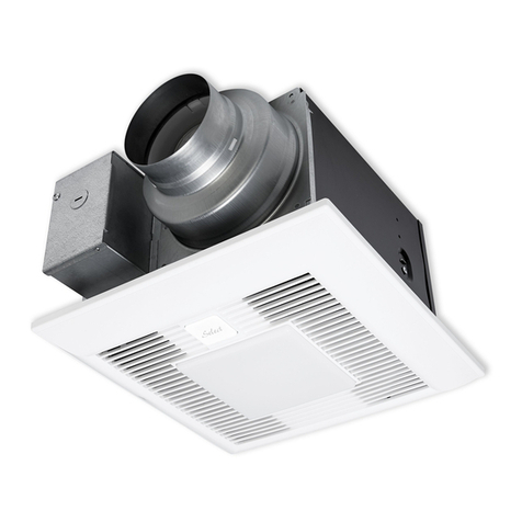
Panasonic FV-05-11VKSL1 installation instructions

Stylies
Stylies TURIA instruction manual

George's
George's 650W instruction manual
