RELACART MIXX 12 User manual

12
10

Open the APP Store application in IPAD, search MIXX12 to download and install
二、MIXX12 Quick connect
MIXX12 Digital Mixer
Contents… … … … … … … … … … … … … … … … 1
Quick Connect Guide … … … … … … … … … … … … … … … … … … … … … … … 2
Product introduction … … … … … … … … … … … … … … … … … … … … … … … 3
MIXX12 introduction, function, technology, parameter … … … … … … … … … … 3
Introduction of Mixer Panel … … … … … … … … … … … … … … … … … … … … … 4
Front panel … … … … … … … … … … … … … … … … … … … … … … … … … … 4
Rear panel … … … … … … … … … … … … … … … … … … … … … … … … … … 5
Instructions for using the interactive operation interface … … … … … … … … … 6
C H 1-1 2 Input channels … … … … … … … … … … … … … … … … … … … … … 8
2 AUX1-4 / DANTE1-4 Auxiliary output / DANTE output… … … … … … … … … … 11
3 EFFECT: Reverb / Echo … … … … … … … … … … … … … … … … … … … … 13
4 GROUP: Grouping … … … … … … … … … … … … … … … … … … … … … … 15
5 48V phantom power … … … … … … … … … … … … … … … … … … … … … … 16
6 EEFFECT: mixing / echo parameters … … … … … … … … … … … … … … … … 17
7 CLEAN SOLO … … … … … … … … … … … … … … … … … … … … … … … … 18
8 CLEAN MUTE … … … … … … … … … … … … … … … … … … … … … … … … 18
9 SYSTEM … … … … … … … … … … … … … … … … … … … … … … … … … … 18
Main output controls … … … … … … … … … … … … … … … … … … … … … … … 19
Troubleshooting Guide … … … … … … … … … … … … … … … … … … … … … … 21
Firmware upgrade steps … … … … … … … … … … … … … … … … … … … … … … 22
Reset the parameters after the WIFI reset … … … … … … … … … … … … … … … 25
… … … … … … … … … … … …
一、Application download
Mixer communicates with IPAD
1: Turn on the power switch of the mixer, open the WIFI setting of IPAD, and connect
to MIXX12 (WIFI factory password: 12345678)
2 Open MIXX12 Software:
192.168.11.254
192.168.11.254
3 Click the software connection status button or system setting button
to enter the connection page.
:
4 Click “Search” to display the IP address,
click the IP address and then click Connect.
:
5 After connection successfully, it will automatically jump to the channel
homepage. The connection status button lights up blue to indicate that
the connection is successful.
:
Quick Connect Guide
Quick Connect Guide
Introduction
Thank you for choosing RELACART digital mixer, and welcome you to join our team
of tens of thousands of professional users. Our professional design and production
experience ensure the excellent performance of our products in terms of quality,
performance and stability. CONNECT
Search
NC
IN OUT
SHOW
INPUTS
MIX
GAIN
0
-7
-15
-22
0
-7-15-22
-30
-30
-37
-37
-45
-45
-52
-52
-60
-60
OUTPUTS
SENDS
Analog
GATE/COMP
MUTE
SOLO
CHANNEL 1
GATE
COMP
GATE PRESET RESET
COMP
MUTE
MAIN
Threshold
Attact
Release
Airplane Mode

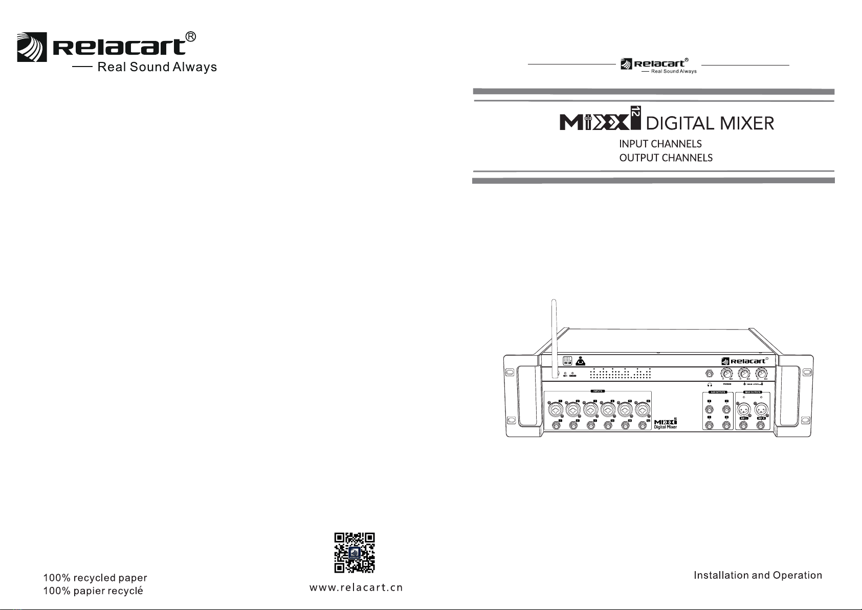
MIXX12 / MIXX12-E is a digital mixer with 12 inputs and 10 outputs. It is a new mixer
equipped with DANTE4 * 4 digital audio transmission module. You can use a network
cable to connect to the router for wireless control, or use the built-in WIFI of the mixer
for wireless control. Can support all Apple ios tablets and Windows tablets. With 6 -
channel broadcast-quality microphone amplifiers (6 combo sockets), 2 main outputs
( dual XLR + dual 6.35 sockets ), 4 auxiliary outputs, 4 DANTE outputs Adopt high -
performance 40-bit floating-point digital signal processor and 24-bit AD/DA converter.
Built-in effects processor, compression, threshold, parametric equalizer. The wireless
control mode allows you to walk on the stage and among the crowd. A 12 - channel
digital live mixer that is perfectly touchable with a tablet such as an iPad.
1. WIFI antenna socket: Install the factory configured WIFI antenna.
2. WIFI: The WIFI indicator flashes when transmitting data.
3. POWER: The power indicator is on to indicate that the power is on.
4. Monitor socket: 6.35MM stereo monitor output socket.
5. PHONE: Stereo monitor output volume adjustment potentiometer.
6. MAIN L OUTPUT potentiometer: The main output left channel volume potentiometer.
7. MAIN R OUTPUT potentiometer: The main output right channel volume potentiometer.
8. Input channel ( MIC / LINE ) : 1-6 channels XLR and 6.35 jack ( JACK ) compatible
balanced input. Cannon type can independently control 48V phantom power.
9. Input channel LINE: 7-12 channel 6.3 jack balanced input.
10. Auxiliary output (AUX 1-AUX4): 4 unbalanced auxiliary outputs, each independently
controlled.
11. MAIN L / R OUTPUTS: The main output XLR and JACK are output in parallel with the
same signal.
12. MAIN L / R OUTPUTS: The main output XLR and JACK are output in parallel with the
same signal.
13. MAIN L / R OUTPUTS LED: main output audio indicator, not controlled by main output
volume potentiometer
Front panel:
Features :
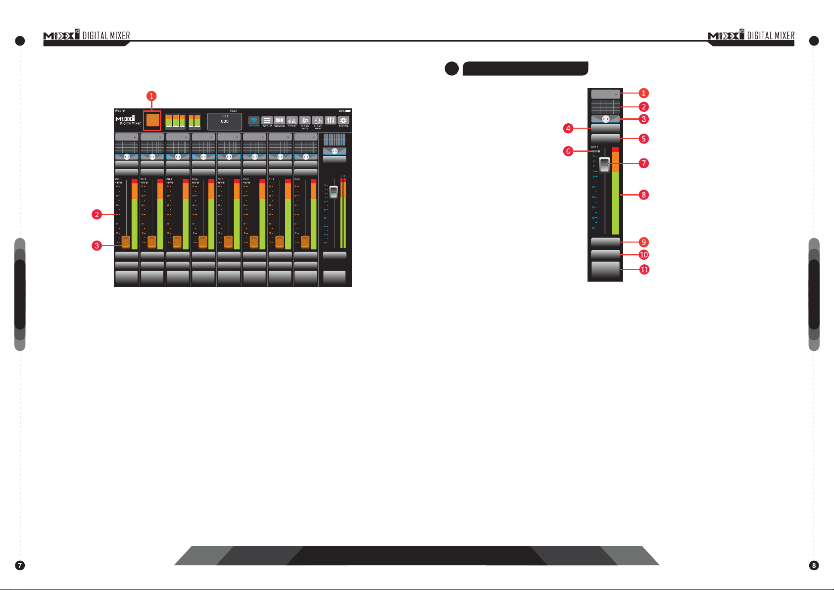
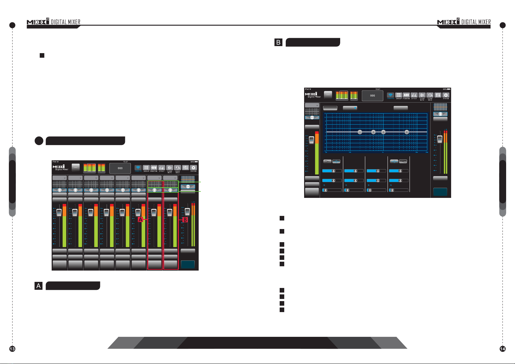
• Intuitive touch controls covering almost all major mixing functions.
• Mixer interface can adjust each channel control, including solo, mute, pan, fader, and see
the complete level meter.
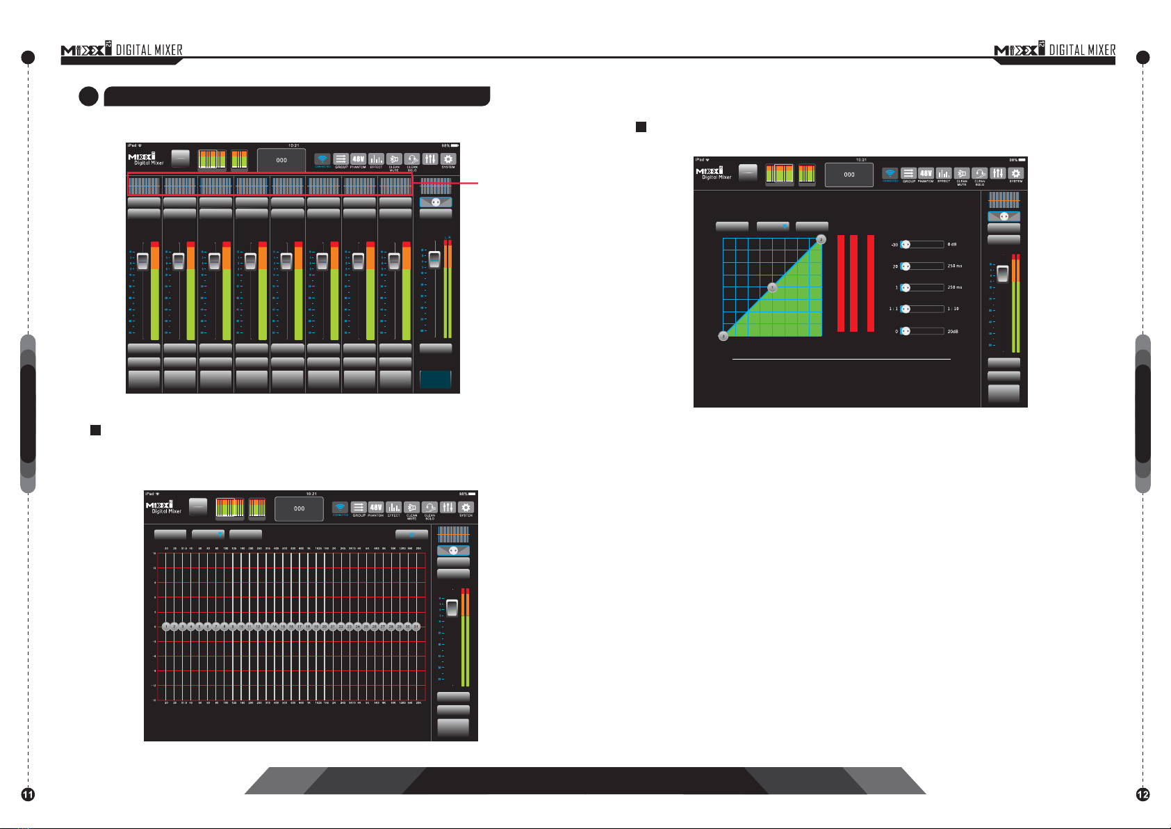
• The channel interface can control powerful DSP effects. The input channels include 4-band
PEQ, high-pass filtering, compression, threshold, main output and auxiliary output,including
31-band graphic EQ and limiter. The effect channel includes reverb and echo.
• Each channel can be edited with names and icons for easy identification, and icons can be
imported from the picture library.
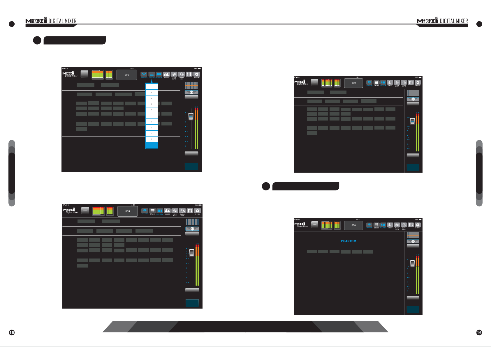
• The +48V phantom power of each channel can be individually switched.(Channel 1-channel 6)
• Extremely low noise floor and extremely high headroom design.
• 4 auxiliary outputs, 4 DANTE outputs can be used to monitor the mix.
• Globally shared reverb and echo effects.
• Seamless access, you can adjust the target's audio at any position in the network domain,
you can go directly to the stage to adjust their own monitoring, and wireless control gives the
musicians on the stage the ability to adjust their own monitoring.
• Can connect a variety of DANTE equipment, such as wireless microphones, conference
microphones, amplifiers and other equipment supporting DANTE communication.
Specification:
Sampling rate:24bit,48kHz
Frequency respond:20 Hz to 20 kHz +/–1 dB
Latency:1.5 ms
T.H.D.:<0.1%
Noise-Mic input to main output:-72dBv Single channel-Max fader(A weighted)
-90dBv Single channel-Min fader(A weighted)
Input crosstalk(adjacent channel):<–120 dB @1 kHz
S/N:93dB One channel and main fader at unity(A-weighted)
Dynamic Range:110dB One channel and main fader at unity(A-weighted)
CMRR:>70 dB @1 kHz
Input Impedance:3.3k Ω(XLR Balance); 30 kΩ(1/4″)
Gain:0 to 60 dB
Output Impedance:600Ω(XLR Balance)
Max Output Level:+21 dBu(XLR Balance)
Power Supply:100-240V AC 50/60Hz
Dimension(mm):488(L)x 132(H)x 191(D)
Weight:Approximately 4kg
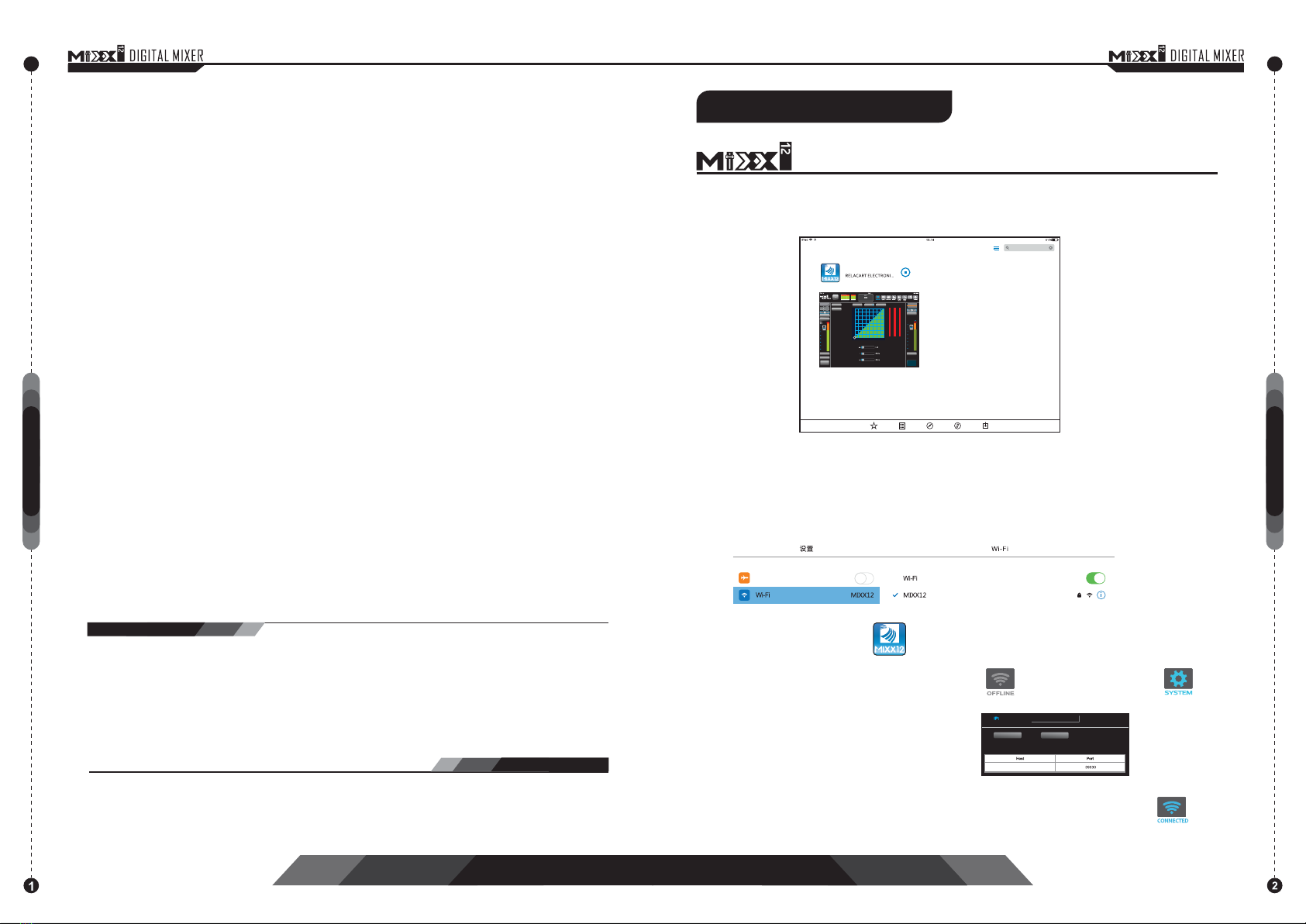
Product introduction Introduction of Mixer Panel

1. AC power interface: Install the factory-configured power cord and connect 110V-240V
50 / 60Hz AC power.
2. Power switch: I / O boat switch, press I to turn on the power, press O to turn off the
power.
3. RESET: Press and hold for 3 seconds to reset DANTE network IP address:
192.168.1.120, press and hold for 6 seconds to reset DANTE network IP + WIFI reset.
(Please refer to WIFI reset parameter setting after resetting WIFI)
4. DANTE network interface: The DANTE interface can transmit audio through the
network, and can also control the mixer through software.
1. MIX / GAIN function switch: A switch that switches the fader to control channel level or
control channel gain.
2. Input channel 1-12 window: display the fader status and input level display of channels
1-12. Click to switch to the input channel page.
3. Output channels AUX 1-AUX 4, DANTE 1-DANTE 4: display output channels AUX 1-
AUX 4, DANTE 1-DANTE 4 The fader status and output level are displayed. Click to
switch to the output page.
4. Software communication status: The icon lights up in blue to indicate online, and gray
to indicate offline.
5. Group function: You can edit mute group and control group to make the channel function
work synchronously.
6. 48V phantom power interface: can independently control phantom power for channels
1-6.
7. Effect parameter setting interface: You can set the effect parameters of reverb and echo.
8. Clear mute switch: Mute all channels that are muted.
9. Clear monitoring: Turn off monitoring for all channels that have monitoring enabled.
10. Performance saving: You can save the set parameters to the performance interface,
and use the saved scene next time after the software connects and communicates
directly.
11. System setting interface: You can enter the connection page, and you can update the
firmware.
12. Main output channel: You can control the function of the main output channel.
13. Function status display window: It is displayed in three lines, the channel currently
being set in the first line, the parameters of the function currently set in the second line,
and the function currently set in the third line.
OUTPUTS SYSTEM SHOW
INPUTS
MIX
GAIN
Analog Analog Analog Analog Analog Analog Analog
Rear panel:
SENDS
Analog
Instructions for using the interactive operation interface
GATE/COMP
MUTE MUTE MUTE MUTE MUTE MUTE MUTE MUTE MUTE
SOLO SOLO SOLO SOLO SOLO SOLO SOLO SOLO
MAIN
CHANNEL 1 CHANNEL 2 CHANNEL 3 CHANNEL 4 CHANNEL 5 CHANNEL 6 CHANNEL 7 CHANNEL 8
GATE/COMP GATE/COMP GATE/COMP GATE/COMP GATE/COMP GATE/COMP GATE/COMP
COMP
SENDS SENDS SENDS SENDS SENDS SENDS SENDS

1. MIX / GAIN function switch: A switch that switches the fader to control channel level
or control channel gain.
White text on a gray background MIX indicates the control channel volume fader (silver
gray), orange low white text GAIN indicates a control channel gain fader (orange).
2. Fader scale: blue for volume scale and orange for gain scale.
3.Channel output volume fader: silver gray adjusts output volume, orange adjusts
channel input gain.
GAIN
AUX
SHOW
INPUTS
MIX
Analog Analog Analog Analog Analog Analog Analog
1. Signal source switching: You can select analog signal or DANTE 1-4 channel signal
input.
2. Input channel EQ: 4-band parametric EQ, which can be arbitrarily controlled within
the setting range, with built-in high and low pass functions.
3. Left and right sound image adjustment (PAN): Adjust the distribution of the sound
source in the space, you can drag left and right, double-click to restore. If it is turned
to the left, it is equivalent to putting the sound source on the left channel,Use this
function in places where stereo sound is required.
4. Noise gate / compressor interface: detailed parameter settings of noise gate and
compressor.
5. AUX Aux Send: Send the volume of the current channel to the output channels AUX
1-4, DANTE 1-4 effect.
6. Channel name and phantom power status: Displays the name of the current channel.
A 48V red light indicates that phantom power is on.
7. Channel fader: Drag the channel up and down to adjust the channel output volume.
The adjustable range is -60dB to + 10dB.
8. Volume level display: The input level display of the current channel.
9. Mute: mute switch. Click this button to turn off the output of the channel audio source.
10. Solo: Monitor switch, click this button, you can use the monitor headphones to hear
the sound signal in front of the channel faders.
11. Channel name: Click this button to allow editing a new name or changing the color
and image.
OUTPUTS SYSTEM
Analog
1CH1-12 Input channels
MUTE MUTE MUTE MUTE MUTE MUTE MUTE MUTE MUTE
SOLO SOLO SOLO SOLO SOLO SOLO SOLO SOLO
MAIN
CHANNEL 1 CHANNEL 2 CHANNEL 3 CHANNEL 4 CHANNEL 5 CHANNEL 6 CHANNEL 7 CHANNEL 8
GATE/COMP GATE/COMP GATE/COMP GATE/COMP GATE/COMP GATE/COMP GATE/COMP GATE/COMP
COMP
SENDS
Analog
GATE/COMP
MUTE
SOLO
CHANNEL 1
SENDS SENDS SENDS SENDS SENDS SENDSSENDS SENDS
GAIN

Input equalizer: 4 - band parametric equalizer, of which BAND 1 and BAND 4 can be
switched between shelves and bells, can be in the range Click "Equalizer", and when
the font color turns blue, you can arbitrarily swap the balls in the range to draw the
equalization effect you want.
Drag the band ball up and down to adjust the gain accordingly. The gain range is
-15dB ~+15dB.
Drag the band ball to the left and right to adjust the frequency accordingly. The gain
range is 20Hz ~ 20KHz.
Q value: Adjust the frequency bandwidth of the frequency sphere.
High-pass: High-pass filter, high-frequency signals can pass normally, while low-
frequency signals below the set threshold are blocked and weakened.
Low-pass: Low-pass filter, low-frequency signals can pass normally, while high-
frequency signals above the set threshold are blocked and weakened.
Preset save: recall preset effects.
Reset: Reset the parameters.
Polarity: The sound wave phase is reversed.
OUTPUTS
GR
OUTPUTS
GR
Noise gate: You can use the noise gate to set a level threshold, and the signal level
above the threshold is normally amplified and lower than the threshold.
The level of the value is off. Generally used to eliminate the background noise when
there is no music signal.
Door valve: Set the threshold value (ie critical level) of the noise door, and the
setting range is -60dB~0dB.
Start-up: The time required for the noise gate to open after the input signal time-out
threshold. The setting range is from 1ms to 250ms.
Recovery: The time required for the noise gate to close after the input signal is less
than the threshold. The setting range is from 20ms to 250ms.
Compressor: An amplifier whose gain decreases as the input signal level increases.
Gate valve: Set the threshold (ie critical level) of the compressor. The setting range
is -60dB~0dB.
Start-up: The time required for the noise gate to open after the input signal time-out
threshold. The setting range is from 1ms to 250ms.
Recovery: The time required for the noise gate to close after the input signal is less
than the threshold. The setting range is from 20ms to 250ms.
Ratio: The compression ratio is 1: 1-1: 10. The larger the compression ratio, the
smaller the compression ratio. The smaller the compression ratio, the larger the
compression ratio.
Preset save: recall preset effects.
Reset: Reset the parameters.
EQ SHOW
INPUTS
MIX
GAIN
OUTPUTS
SENDS
Analog
GATE/COMP
MUTE
SOLO
CHANNEL 1
MUTE
MAIN
COMP
EQ PRESET RESET POLAR
BAND 1 BAND 2 BAND 3 BAND 4
GAIN GAIN GAIN GAIN
FREQUENCY FREQUENCY FREQUENCY FREQUENCY
HPF
LPF
NC
IN OUT
SHOW
INPUTS
MIX
GAIN
0
-7
-15
-22
0
-7-15-22
-30
-30
-37
-37
-45
-45
-52
-52
-60
-60
OUTPUTS
SENDS
Analog
GATE/COMP
MUTE
SOLO
CHANNEL 1
GATE
COMP
GATE PRESET RESET
COMP
MUTE
MAIN
Threshold
Attact
Release
NC SHOW
INPUTS
MIX
GAIN
OUTPUTS
SENDS
Analog
GATE/COMP
MUTE
SOLO
CHANNEL 1
GATE COMP PRESET RESET
COMP
MUTE
MAIN
Threshold
IN OUT
0
-7
-15
-22
0-7-15-22
-30
-30
-37
-37
-45
-45
-52
-52
-60
-60
COMP
Attact
Release
Ratio
Gain

2AUX1-4 / DANTE1-4 Auxiliary output / DANTE output
Gate valve: Set the threshold (and critical level) of the compressor. The setting range
is -60dB~0dB.
Start-up: The time required for the noise gate to open after the input signal time - out
threshold. The setting range is from 1ms to 250ms.
Ratio: The compression ratio is 1:1-1:10. The larger the compression ratio, the smaller
the compression ratio. The smaller the compression ratio, the larger the compression
ratio.
Preset save: recall preset effects.
Reset: Reset the parameters.
Gain: Adjust the compensation gain of the compressor.
OUTPUTS COMP SHOW
INPUTS
MIX
GAIN
IN OUT GR
0
-7
-15
-22
0-7-15-22
-30
-30
-37
-37
-45
-45
-52
-52
-60
-60
MAIN
Click this button, the main interface area is displayed as shown in the figure
AUX 1
EQ
OUTPUTS
SHOW
INPUTS
MIX
GAIN
Pre Fader
A 1
Auxiliary output equalizer: The standard 31-band graphic equalizer compensates
the defects of speakers and sound field by adjusting various frequency bands. Click
"Draw", and when the font color turns blue, you can drag the frequency ball in the
range to draw the balance effect you want.
Compressor: An amplifier that reduces its gain as the input signal level
increases.
AUX 1 - 6 SHOW
MUTE MUTE MUTE MUTE MUTE
SOLO SOLO SOLO SOLO
MAIN
AUX 5 AUX 6 AUX 7 AUX 8
OUTPUTS
INPUTS
MIX
GAIN
MUTE MUTE MUTE MUTE
SOLO SOLO SOLO SOLO
AUX 1 AUX 2 AUX 3 AUX 4
A 1 A 2 A 3 A 4 D 1 D 2 D 3 D 4
AUX 1
COMP
Pre Fader
COMP
Pre Fader Pre Fader Pre Fader Pre Fader Pre Fader Pre Fader Pre Fader
COMP COMP COMP COMP COMP COMP COMP
Equalizer
EQ PRESET RESET
COMP
AUX 1
SOLO
MUTE
Threshold
Attact
Release
Ratio
Gain
COMP PRESET RESET Pre Fader
A 1
COMP
AUX 1
SOLO
MUTE

Drag the band ball up and down to adjust the gain accordingly. The gain range is
-15dB~15dB.
Drag the frequency ball to the left and right to adjust the gain accordingly. The gain
range is 20Hz~20KHz.
Q value: Adjust the slope of the audio curve.
Preset save: recall preset effects.
Reset: Reset the parameters.
Left and right sound image adjustment (PAN): Adjust the distribution of the sound
source in space, you can drag left and right, double-click to restore. If it is adjusted
to the left, it is equivalent to placing the sound source on the left channel, and uses
this function in places requiring stereo.
Auxiliary: Adjust the level of the sound source of each channel to the auxiliary output.
Channel fader: Drag up and down to adjust, the adjustable range is -60dB~10dB.
Mute: mute switch, click this button to turn off the input of the channel audio source.
Solo: monitor switch, click this button, you can use the monitor to listen to the sound
signal in front of the fader.
Input equalizer: 4-band parametric equalizer, of which BAND 1 and BAND 4 can be
switched between the shelf and the bell shape, and the frequency, gain and Q value
can be arbitrarily set within the range. Click "Equalizer". When the font color turns
blue, you can drag the band ball anywhere in the range to draw the equalization
effect you want.
Before Fader: Click this button to select Pre Fader, Post Fader, or Pre Dsp.(Before
the fader) indicates that the signal is not limited by the fader. If you do n't push the
fader, there is a signal output. After the fader, it means that the fader will not be
pushed, and the signal will not be sent out.
Pre Dsp: If you select this button, you will hear no preset analog sound.
Auxiliary channel fader: drag up and down to adjust, adjustable range: -60dB~10dB.
Mute: mute switch, click this button to turn off the input of the channel audio source.
Solo: monitor switch, click this button, you can use the monitor headphones to hear
the sound signal in front of the fader of the channel.
Channel name: Click this button to allow editing a new name or changing the color
and image.
Click this button, the main interface area is displayed as shown in the figure:
Input equalizer: 4 - band parametric equalizer, of which BAND 1 and BAND 4 can be
switched between shelves and bells, which can be arbitrarily within the range. Set the
frequency, gain and Q value. Click "Equalizer", when the font color turns blue, you can
drag the frequency band arbitrarily within the range Draw the balance you want.
3EFFECT: Reverb / Echo
DELAY (Echo):
DELAY (Echo):
OUTPUTS PHANTOM SHOW
INPUTS
MIX
GAIN
Analog Analog Analog Analog Analog Analog Analog
SENDS
Analog
GATE/COMP
MUTE MUTE MUTE MUTE MUTE MUTE MUTE MUTE MUTE
SOLO SOLO SOLO SOLO SOLO SOLO SOLO SOLO
MAIN
CHANNEL 7 CHANNEL 8 CHANNEL 9 CHANNEL 10 CHANNEL 11 CHANNEL 12 ECHO REVERB
GATE/COMP GATE/COMP GATE/COMP GATE/COMP GATE/COMP
COMP
SENDS SENDS SENDS SENDS SENDS
CH 7 CH 8 CH 9 CH 10 CH 11 CH 12 ECHO REVERB
SENDS SENDS
Input equalizer
Left and right
channel
adjustment
OUTPUTS
DELAY
EQ SHOW
INPUTS
MIX
GAIN
SENDS
Analog
MUTE
SOLO
ECHO
EQ PRESET RESET
BAND 1 BAND 2 BAND 3 BAND 4
GAIN GAIN GAIN GAIN
FREQUENCY FREQUENCY FREQUENCY FREQUENCY
ECHO
MUTE
MAIN
COMP
RECERB

There are 4 mute groups and 4 control groups. After clicking GROUP, a pop-up picture
is displayed, click "Edit", the main screen area enters the mute / control interface.
Mute group : After entering the mute editing interface, as shown in the figure: Click
"Mute 1" to select 1, 3, 6, 8 channels, and then click the group "1" in the mute drop-
down menu, then 1, 3, 6, 8 channels are Mute.
Control grouping: After entering the control editing interface, as shown in the figure:
click “Control 1”, select 1, 2, 3, 4 channels, then select the function you want to adjust
at the same time, and then click the control group “1” in the drop-down menu In this
way, the parameters of 1, 2, 3, and 4 channels can be adjusted at the same time.
Control the switching state of 48V phantom power of 12 input channels independently.
Click this button, the main screen area is displayed as shown in the figure: which
channel requires 48V power supply, click on the corresponding channel, the
corresponding channel's 48V icon will light up.
4GROUP: Grouping
548V phantom power
REVERB
PHANTOM SHOW
INPUTS
MIX
GAIN
REVERB
MAIN
MUTE 2MUTE 3MUTE 4
ECHO AUX 3 AUX 4 DANTE 1 DANTE 2 DANTE 3 DANTE 4
AUX 3AUX 2AUX 1 AUX 4 DANTE 1 DANTE 2 DANTE 3
DANTE 4
OUTPUTS
MUTE
MAIN
COMP
MUTE
CONTROL
EDIT
MUTE CONTROL
CHANNEL 1 CHANNEL 2 CHANNEL 3 CHANNEL 4 CHANNEL 5 CHANNEL 6 CHANNEL 7 CHANNEL 8
CHANNEL 9 CHANNEL 10 CHANNEL 11 CHANNEL 12
MUTE 1
REVERB
PHANTOM SHOW
INPUTS
MIX
GAIN
REVERB
MAIN
MUTE 2MUTE 3MUTE 4
ECHO AUX 3 AUX 4 DANTE 1 DANTE 2 DANTE 3 DANTE 4
AUX 3AUX 2AUX 1 AUX 4 DANTE 1 DANTE 2 DANTE 3
DANTE 4
OUTPUTS
MUTE
MAIN
COMP
MUTE CONTROL
CHANNEL 1 CHANNEL 2 CHANNEL 3 CHANNEL 4 CHANNEL 5 CHANNEL 6 CHANNEL 7 CHANNEL 8
CHANNEL 9 CHANNEL 10 CHANNEL 11 CHANNEL 12
MUTE 1
REVERB
PHANTOM SHOW
INPUTS
MIX
GAIN
OUTPUTS
MUTE
MAIN
COMP
CHANNEL 1 CHANNEL 2 CHANNEL 3 CHANNEL 4 CHANNEL 5 CHANNEL 6

SHOW
SYSTEM
OUTPUTS
CH 1
0.0 dB
INPUTS
MIX
GAIN
MUTE
MAIN
COMP
CONNECT HELP
SEARCH CONNECT
DEVICE SETTING
Effects (reverberation): Its role is to change the waveform of the original sound,
adjust or delay the phase of the sound wave, enhance the harmonic components
of the sound wave, and other measures to produce a variety of special sound
effects, and apply Effects to the sound. ).
Delay (1, 2, 3, 4): The time required for the sound to return to the human ear after
transmission, with a range of 30ms to 100ms. The 4-segment delay group makes
the sound superimposed more delicate, making the sound effect fuller and more
beautiful.
Reverberation time: The duration of the reverberation effect. The setting range is
0.1S~10S.
Low-pass: Low-pass filter, the setting range is 20Hz ~ 20000Hz.
The reverberator has the functions of preset saving, resetting parameters, input
level, output level adjustment and mute switch function.
Delayer (echo): Delayer is an effector that produces echo.
Delay 1: Control the interval time of echo 1: The range is 10ms ~ 1000ms.
Delay 2: Control the interval time of echo 2: The range is 10ms ~ 1000ms.
The longer the delay time, the longer the interval between echoes, until the double
or multiple sounds can be clearly heard.
Feedback Amplitude: The feedback rate of the echo effect, setting range (0% to
100%), controlling the number of echoes. When the feedback rate is 0%, the echo
actually plays the effect of reverberation, and the feedback rate is 100% At this time,
an endless echo effect will be formed, so the echo effect is generally controlled at
about 30%.
Decrease: The echophone has the functions of preset saving, resetting
parameters, input level, output level adjustment and mute switch function.
Connect: Connect to the target host through the searched host or manually enter the IP.
Help: Provides a quick start guide and upgrades the console firmware over the network.
After clicking this button, the monitoring function of all channels will be cancelled after 2
seconds.
Click this button to cancel the mute function of all channels after 2 seconds
EEFFECT: mixing / echo parameters
67CLEAN SOLO
8
9
CLEAN MUTE
SYSTEM
SHOW
INPUT
OUTPUTS
DELAY
0.0 dB
INPUTS
INP UT
54
56
49
76
0.8
19952
46
241
168
19952
5.0s
20 KHz
20 KHz
100%
1000 ms
1000 ms
REVERB PRESET RESET
Delay 1
Delay 2
Delay 3
Delay 4
Decay
LPF
MUTE MUTE
OUT PU T
ECHO PRESET RESET
Pre D...
Delay
Feedback
LPF
INP UT O UTP UT
MUTE MUTE
MIX
GAIN
SENDS
Analog
MUTE
SOLO
REVERB
REVERB
MUTE
MAIN
COMP
REVERB
ECHO

MUTE
MAIN
COMP
Gate valve: Set the threshold (critical level) of the compressor.
is -60d~0dB.
Start-up: The time required for the noise gate to open after the input signal time-out
threshold. The setting range is from 1ms to 250ms.
Recovery: The time required for the noise gate to close after the input signal is less
than the threshold. The setting range is from 20ms to 250ms.
Ratio: The compression ratio is 1: 1-1: 10. The larger the compression ratio, the
smaller the compression ratio. The smaller the compression ratio, the larger the
compression ratio.
Gain: Adjust the compensation gain of the compressor.
Main output fader: drag up and down to adjust, adjustable range: -60dB~10dB.
Mute: Controls the mute switch of the main output.
The setting range
Main output compressor: You can set a level point. Once the signal exceeds this
critical point, the volume will be attenuated and the overall volume will be stable,
so as to avoid howling or overload the amplifier.
Main output channel function:
Main output equalizer: The standard 31-band graphic equalizer compensates the
defects of speakers and sound field by adjusting various frequency bands. Click
"Draw", you can drag the frequency ball in the range to draw the equalization
effect you want.
Main output controls
INPUTS
MIX
GAIN
0
-7
-15
-22
-30
-30
-37
-37
-45
-45
-52
-52
-60
-60
COMP PRESET
OUTPUTS COMP
IN OUT GR
0-7-15-22
MAIN
Threshold
Attact
Release
Ratio
Gain
RESET
SHOW
COMP
MUTE
MAIN
Input equalizer
Left and right channel adjustment
AUX 1
EQ
OUTPUTS
SHOW
INPUTS
MIX
GAIN
EUEALIZER PRESET RESET
COMP
MAIN
MUTE
DRAW
L R
L R

OUTPUTS SYSTEM SHOW
INPUTS
MIX
GAIN
Analog Analog Analog Analog Analog Analog Analog
SENDS
Analog
GATE/COMP
MUTE MUTE MUTE MUTE MUTE MUTE MUTE MUTE MUTE
SOLO SOLO SOLO SOLO SOLO SOLO SOLO SOLO
MAIN
CHANNEL 1 CHANNEL 2 CHANNEL 3 CHANNEL 4 CHANNEL 5 CHANNEL 6 CHANNEL 7 CHANNEL 8
GATE/COMP GATE/COMP GATE/COMP GATE/COMP GATE/COMP GATE/COMP GATE/COMP
COMP
SENDS SENDS SENDS SENDS SENDS SENDS SENDS
Home screen area
No sound? Troubleshooting guide
Is the threshold closed?
Incorrect threshold processor settings may cause all signals to be intercepted. This
happens most often when the threshold is set too high and the signal is not large
enough to make the threshold "open".
Is the fader up?
The channel fader needs to be set to a sufficiently high level. If the problematic output
path is in front of the fader, the fader position has no effect on its signal.
Is the output main channel path valid?
The inspection method is basically the same as the output channel inspection method,
and the same inspection is run on the output channel.
Is the physical output valid?
Check the connections and your amplifier system.
If the meter shows a valid output, then the problem may be with the physical output or
after the physical output.
1: Network connection between computer / tablet and MIXX12.
2 Open the software and search for the target IP. After searching, click the IP address.
Do not click Connect.
:
DANTE network port or WIFI operation steps are the same
Troubleshooting Guide
CH 1
MUTE
CLOSE
HELP
CH 9-12
MIX
GAIN
CH 1-8
SHOWCONNECT
OK
OK
OFFLINECONNECT
Search
DEVICE SETTING
SPAN TIME
IP:
DE VICE IP PO RT
192.168.11.254 39030
192.168.11.254
100

24
3 Switch to the help page and click Local Upgrade. Do not click repeatedly or you will
get an error. After clicking, the firmware will start to upgrade, as shown below:
:
4 When the progress bar finishes running twice, a prompt window Update successfully
is displayed, indicating that the upgrade was successful. After the upgrade is successful,
restart the console and control software.
:
5 If the upgrade is unsuccessful, the Update fail prompt window appears. Please check
the upgrade steps and upgrade again.
:
MIX
GAIN
CH 1-8
Current version: 1.1
Local version: 1.1
CONNECT SHOW
CH 1
MUTE
CLOSE
AUX
RESET
LOCAL
HELP
确 定
update fail
MIXX12
OFFLINE
CH 9-12
MIX
GAIN
CH 1-8
Current version: 0.0
Local version: 1.1
CONNECT SHOW
CH 1
MUTE
CLOSE
RESET
LOCAL
HELP
CH 9-12
MIX
GAIN
CH 1-8
Current version: 1.1
Local version: 1.1
CONNECT SHOW
CH 1
MUTE
CLOSE
AUX
RESET
LOCAL
HELP
确 定
update fail
MIXX12
OFFLINE
CH 9-12

25 26
2 The WIFI password for connecting HI-LINK is: 12345678:
3 Open your browser, enter IP: 192.168.16.254 in the address bar, and press Enter.
Login account and password: admin
:
(Press and hold the RESET key for 3 seconds to reset the factory fixed IP address of
the DANTE network port. Press and hold for 6 seconds to reset the factory fixed IP +
WIFI setting of the DANTE network port.)
1: Wait for 20 seconds after WIFI reset, search for the WIFI name connection of
HI-LINK.
192.168.11.254
http://192.168.16.254/
+
x
4 Change the webpage to Chinese, click the HLK-RM04 page (see Figure 1):
PIC 2:
Modify the parameters in Figure 1 according to the box in Figure 2 without any difference.
After confirming the modification is correct, click OK. Just close the page.Connect to the
network.
Reset the parameters after the WIFI reset
HLK-RM04 Web Configure +
http://192.168.16.254/Serial2Net.asp
x
WIRELESS-N ROUTER IEEE 802.11N
HLK-RM-04 Serial2Net Settings
Engl i s h 简 体中文
Serial2Net Settings
Advance Settings
Serial2Net UART 2 Settings
Administration
SSID:
Password:
HLK-RM0 4
Default
HI-LINK_298B
12345678
Current Updated
Serial Configure:
Serial Framing Lenth:
Serial Framing Timeout:
Network mode:
Remote Server Domain/IP:
Locale/Remote Port
Number:
Network Protocol:
Network Timeout:
115200,8,n,1
64
10milliseconds
server
192.168.11.245
8080
tcp
0 seconds
115200,8,n,1
192.168.11.245
8080
0
64
100
TCP
Server
Apply Cancel
milliseconds
no timeout)
(<256,0 for
seconds for
no timeout)
(<256,0
NetMode:
HLK-RM04 Web Configure +
http://192.168.16.254/Serial2Net.asp
x
WIRELESS-N ROUTER IEEE 802.11N
HLK-RM-04 Serial2Net Settings
Engl i s h 简 体中文
Serial2Net Settings
Advance Settings
Serial2Net UART 2 Settings
Administration
HLK-RM0 4
Current Updated
Serial Configure:
Serial Framing Lenth:
Serial Framing Timeout:
Network mode:
Remote Server Domain/IP:
Locale/Remote Port
Number:
Network Protocol:
Network Timeout:
115200,8,n,1
64
10milliseconds
server
192.168.11.245
8080
tcp
0 seconds
230400,8,n,1
192.168.11.245
39030
0
70
100
UDP
Server
Apply Cancel
milliseconds
no timeout)
(<256,0 for
seconds for
no timeout)
(<256,0
NetMode:
SSID:
Encrypt Type:
Password:
IP Address:
Subnet Mask:
WIFI-(AP)-SERIAL
PIC 1:
12345678
HI-LINK
HI-LINK

2827
5 Wait for 20 seconds and search again for WIFI name: MIXX12, and the connection
password is 12345678
:
6 After setting the WIFI parameters according to the above 5 steps, if you need to
modify the WIFI name and password, or the connection software is abnormal, the IP
that needs to re-enter the setting interface has changed: 192.168.11.254, the login
account and password are also: admin
:
192.168.11.254
http://192.168.11.254/
+
x
12345678
Table of contents
Other RELACART Music Mixer manuals