Reliable Equipment REL-EP-115 Manual

1
OPERATORS’ GUIDE
REL-EP-115/230 Manual 05-16
RELIABLE EQUIPMENT & SERVICE CO., INC.
301 Ivyland Road • Warminster, PA 18974 • USA
Phone: 215-357-3500 • Fax: 215-357-9193
MODEL: _____________________
SERIAL NO.: ____________
YEAR: ___________
REL-EP-115/230
SINGLE / DOUBLE ACTING 1
0
,
000
PSI
CONTIUOUS DUTY ELECTRIC HYDRAULIC PUMP
2.0 hp
Continuous Duty
Electric Motor
REL-EP-115/230
SINGLE / DOUBLE ACTING
10,000 PSI CONTIUOUS DUTY
ELECTRIC HYDRAULIC PUMP
The REL-EP-115/230 single and
double acting hydraulic pump features
manual lever operation, continuous
duty performance, and a two stage
pumping system, to ensure
rapid tool advance.
The manual lever control valve,
and factory installed couplers
are ready to run your single or
double acting crimping, cutting
and spearing tools.
REL-EP-115
115 Volt
REL-EP-230
230 Volt
WARNING
All information found in this guide must
be read and understood before use or
testing of this tool.
Failure to read and understand these warnings
and safe handling instructions could result in
severe personal injury and or death.

2
DISTRIBUTED BY
REGISTRATION
UPON RECEIPT OF THIS TOOL, COMPLETE THE REGISTRATION BELOW.
COMPANY __________________________________________________________
ADDRESS ___________________________________________________________
_____________________________________________________________________
PHONE _____________________ FAX __________________________________
SERIAL NUMBER ____________________________________________________
DATE OF PURCHASE ________________________________________________
DEALER NAME ______________________________________________________
NOTICE
Sizes, weights and tool specifi cations listed in
this manual are subject to change without notice.
Consult factory for information and updates.

3
TABLE OF CONTENTS
Registration ..................................................................................................................... 2
Table of Contents & Safety Reference Information ......................................................... 3
Tool Quick Reference ....................................................................................................... 4
General Safety Issues ...................................................................................................5-7
SAFETY - System Installation, Pre-Operation and Removal .........................................8-10
Hose Connections and Installation ................................................................................. 8
Pre-Operation of Tool, Disconnecting Hoses .................................................................. 9
SPECIFICATIONS
Hydraulic Fluid ............................................................................................................... 10
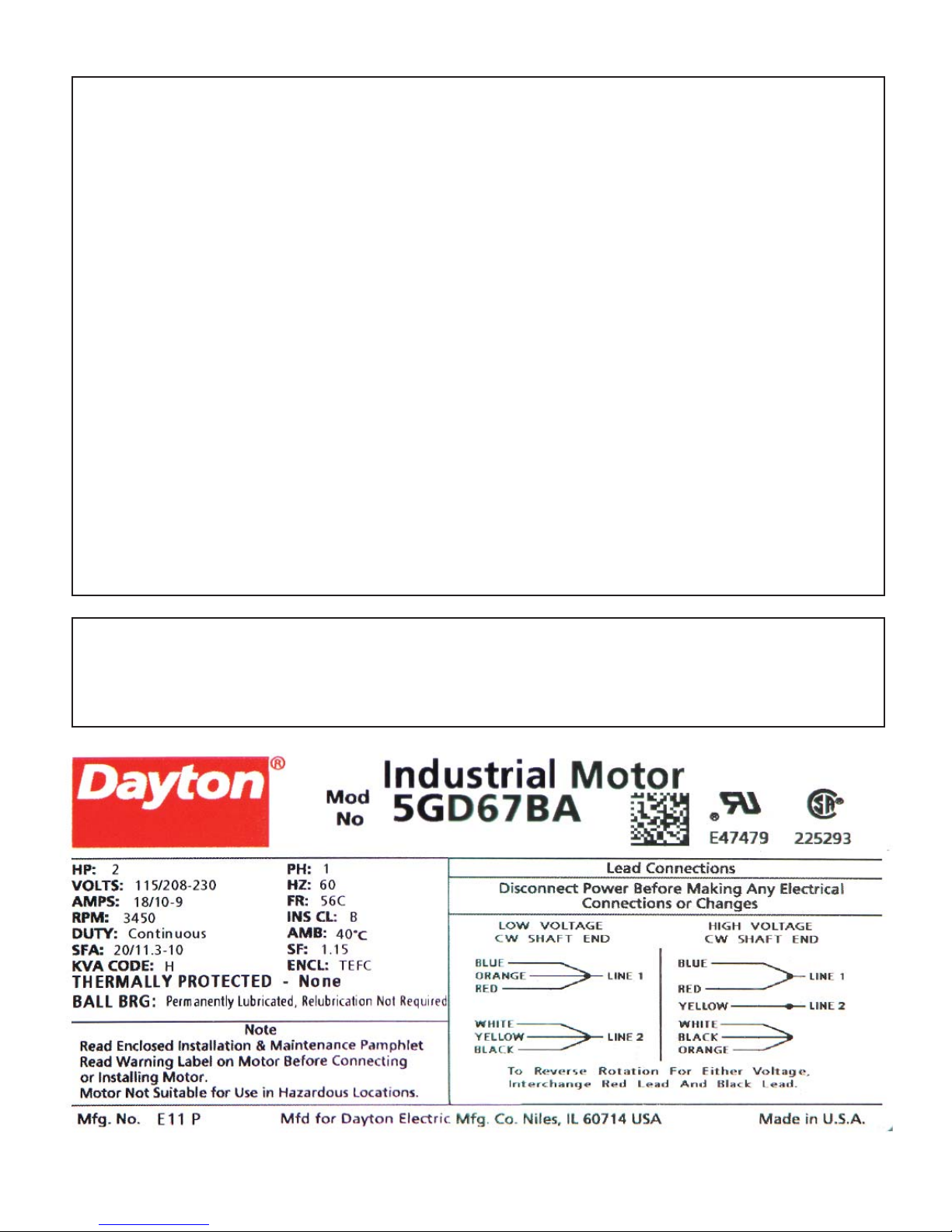
Tool & Motor Specifications ........................................................................................... 10
Visual References .....................................................................................................11-12
Operation (Single Acting) ............................................................................................... 13
Operation (Double Acting) ............................................................................................. 14
MAINTENANCE
Scheduled Maintenance & Label Reference ................................................................. 15
Troubleshooting ........................................................................................................... 16
Before Disassembly, Reservoir Clean & Fill ................................................................. 17
DRAWINGS Major Components (Fig. 1) ................................................................ 18
Inner Pump Assembly (Fig. 2) ........................................................... 19
PARTS LISTS Major Components & Inner Pump ..................................................... 20
Valve Block Assembly ........................................................................ 21
DRAWING Valve Block Assembly (Fig. 3) ............................................................ 22
High Pressure Pump Block (Fig. 4 ), Manifold Outlet Block (Fig. 5) .23
PARTS LISTS High Pressure Pump Block, Manifold Outlet Block
Low Pressure Pump Assembly ........................................................... 24
DRAWING Low Pressure Pump Assembly (Fig. 6) .............................................. 25
Maintenance Record ...................................................................................................... 25
User Notes, Contact Information & Visual Warnings ................................................... 26
THIS SYMBOL INDICATES ITEMS OF EXTREME IMPORTANCE.
Safety of user and others may be in jeopardy if these instructions are not
read and understood.
Operation/Safety methods may vary in accordance with the working
guidelines established by each utility or contractor
For your own safety, ensure that you fully comply with all safe operation
guidelines required by your employer.
WARNING

4
REL-GB-10 or REL-EP-115
4 CYCLE GASOLINE or ELECTRIC
SINGLE AND DOUBLE ACTING
10,000 PSI HYDRAULIC PUMPS
The REL-GB-10 and REL-EP-115 single
and double acting hydraulic pumps feature
manual lever operation, continuous duty
performance, and a two stage pumping
system, to ensure rapid tool advance.
The manual lever control valve, and factory
installed couplers are ready to run your
single or double acting crimping, cutting
and spearing tools.
REL-EP-115 -2.0 hp electric
115V (18A) continuous duty motor.
REL-EP-230- 230V (10A) continuous duty.
REL-GB-10 - 8.75 ft./lb. torque,190cc
Briggs & Stratton OHV 4 stroke engine.
FEATURES:
10,000 PSI high pressure pump.
Fast, two stage pumping system.
Factory fi lled 2 gallon fl uid reservoir with
recessed sight glass.
High-pressure relief valve.
NO CONVERSION NECESSARY
Single/Double selector knob.
Integral manual lever control valve.
Designed for use with high pressure single
& double-acting, hydraulic tools.
REL-GB-10 has a steel support frame.
REL-EP-___ has a balanced carry handle.
RELIABLE EQUIPMENT & SERVICE CO., INC.
301 Ivyland Road • Warminster, PA 18974
Call:
800-966-3530
• FAX:
215-357-9193
Visit our web sight: www.Reliable-Equip.com

5
WARNING
BEFORE USING THIS TOOL, READ THE WARNINGS
and the recommended practices described in this manual.
Failure by the operator to read and fully understand these
warnings will leave this person unqualified to use and
operate this tool. Property damage, severe personal injury,
and/or death could result by not following these warnings.
Eye
Protection
These warnings will appear in appropriate locations when they are pertinent to the
particular subject being shown. Read each one carefully and follow them strictly.
WARNING
Always wear eye protection to avoid
injury from flying debris or hydraulic
oil leaks. Failure to do so can result in
serious personal injury.
Hard Hat
WARNING
Always wear a hard hat to avoid injury
from falling debris. Failure to do so can
result in serious personal injury.
Hearing
Protection
WARNING
Always wear hearing protection, to
avoid hearing loss due to long term
exposure to high noise levels.
Foot
Protection
WARNING
Always wear foot protection.
Failure to do so can result in serious
personal injury.
Dust Mask
WARNING
Always wear a Mask.
Failure to observe this warning may
result in serious health issues and/or
breathing diffi culty.
WARNING
Protective
Gloves
Always wear protective gloves.
Failure to do so can result in serious
personal injury.

6
WARNING
Safety
DO NOT attempt to make any changes to any of the component
parts or accessories when connected to the power source.
DO NOT adjust, inspect, or clean tool while the tool is connected
to the power source. The tool could accidentally start up and
cause serious injury.
DO NOT lock the tool in the On Position. In an emergency, serious
damage or injury could occur during the time required to stop
the tool.
Safe Operation & Care
USE THIS TOOL FOR ITS INTENDED PURPOSE ONLY
Any other use can result in injury or property damage.
INSPECT TOOL BEFORE USE. Replace any worn, damaged or
missing parts. A damaged or improperly assembled tool may
malfunction, injuring operator and/or nearby personnel.
INSPECT HYDRAULIC HOSES AND COUPLINGS before each use.
Repair or replace if any cracking, leakage, wear or damage is is
found. Worn or damaged hoses may fail resulting in personal
injury or property damage.
CLEAR WORK AREA of all bystanders and unnecessary personnel
before operating this tool.
KEEP ALL PARTS OF THE BODY AWAY FROM MOVING PARTS.
Failure to observe this warning could result in serious injury.
WARNING
Oil Injection Injury
Hydraulic oil or fluid under the skin is a serious injury. Oil under
pressure can penetrate the skin and may cause dismemberment
or loss of life. Seek medical assistance immediately if such an
injury should occur.
Always wear safety gloves, eye protection and all required
safety equipment when operating or handling this tool.
DO NOT use fingers or hands to attempt to locate a leak.
DO NOT handle hoses or couplers while system is pressurized.
NEVER open or service the system before depressurizing.
WARNING

7
Safe Handling
HYDRAULIC FLUID MAY CAUSE SKIN IRRITATION.
Prevent hydraulic fl uid from making contact with skin.
IN THE EVENT OF SKIN CONTACT immediately wash thoroughly.
Failure to observe this warning could result in injury.
CAUTION
Electrical Shock Hazard
Use only certified non-conductive hoses and fittings.
Always wear and use the necessary clothing, equipment and
safety practices to protect against electrical shock. Failure to
follow these rules can result in serious personal injury or death.
WARNING
CAUTION
General Safety
Ensure that all fellow employees and bystanders are clear
and protected from possible injury caused by this tool or the
operations being performed. Persons in close proximity could
be injured and property damaged if the tool were to malfunction.
This tool should always be used within the limits and purposes
stated by the product manufacturer. Abuse or usage beyond the
manufacturers’ intended purposes could cause damage to the tool
and severe injury to the operator.
Burn Hazard
Do Not connect or disconnect tool, hoses or fi ttings while power
source is running or while hydraulic fl uid is hot.
Hot hydraulic fl uid may cause serious burns.
Failure to observe this warning could result in serious injury.
WARNING
If you have any questions regarding the information found in this
manual please contact RELIABLE EQUIPMENT before continuing.
Phone: 215-357-3500 Toll Free: 800-966-3530 Fax: 215-357-9193
NOTICE

8
HOSES AND FITTINGS
There exists the potential for shock in using anything other than
certified nonconductive hoses and hydraulic oil with dielectric
properties, when using system components near energized
electrical lines. Failure to recognize these conditions could
cause electrocution.
Hoses and fittings used with this tool must comply with S.A.E. J1273 which
covers recommended practice for selection, installation, and maintenance of hose and
hose assemblies. The correct hoses and fittings are available from your supplier.
WARNING: Failure to comply with these warnings could result in severe bodily injury.
WARNING
UNIT/HOSE CONNECTIONS
ALWAYS DISCONNECT pump/power source and move toggle
switch to OFF before connecting or disconnecting any components.
ALWAYS DEPRESSURIZE hydraulic system, before slowly
disconnecting this unit or any of the systems components.
ALWAYS TIGHTEN couplings completely. Loose or improperly
tightened couplings will not allow fluid to pass through the
hose creating a blockage in the supply or return line.
ALWAYS INSPECT HOSES AND CONNECTORS before connection
to tool. Replace or repair if any leakage is evident. Leakage is a sign
of deterioration in component parts. Worn or leaking parts must be
repaired or replaced, or tool damage or severe injury could result.
WARNING
HOSE INSTALLATION
ALWAYS ENSURE CONNECTORS ARE CLEAN
SINGLE ACTING - Connect the hose to the pressure port
on the power source, then connect to the port on the tool.
DOUBLE ACTING - Care must be taken to assure the correct
connection of the hoses to the pressure and return (tank) ports.
Connect the return hose to the return (tank) port on the power source,
then to the return port on the tool.
Connect the pressure hose to the pressure port on the tool, then to
the “P” pressure port on the power source.
Operation with hydraulic flow reversed can cause malfunction.
Failure to fully comply can result in severe injury or death.
CAUTION

9
PRE-OPERATION OF TOOL
Before attempting to run or use the REL-SERIES pump, check all connections, including
hoses, and couplings. (See WARNINGS on page 8)
Wear all safety items required and make sure that the working area is clear of obstructions
and non-essential personnel.
DO NOT connect hoses or fittings to pump before reading all of
the instructions in this Manual completely.
Ensure power source is OFF, and hydraulic flow is turned OFF.
Failure to comply with warnings can result in severe injury or death.
WARNING
HYDRAULIC FLUIDS
All hydraulic fluids that meet these listed specifications or the listed HTMA specifications
may be used for this tool.
S. U. S.
@ 100OF (38OC) ................................................................ 140 TO 225
@ 210OF (99OC) .............................................................. 40 minimum
FLASH POINT ............................................. 340OF min. (170O C min.)
POUR POINT ...................................................-30OF min. (-34OC min.)
DISCONNECTING HOSES
WARNING: DO NOT disconnect the tool, hoses, or fittings while
the tool is running, hot, or under pressure. Serious injury or burns
could result.
Turn pump OFF and disconnect from power source.
NOTE: It is advised that control valves be cycled with the power
off to relieve any residual pressure trapped within the line before
disconnecting the hoses.
Ensure valve lever is in the RIGHT (RET.) position and remove
hose(s).
Disconnect the pressure hose from the pressure “P” port on the
pump, then disconnect the hose from the pressure port on the tool.
Disconnect the return hose from the return “T” port on the tool,
then disconnect the hose from the return (tank) port on the pump.
Install dust caps on all connectors to prevent dirt and contam-
inents from entering the hydraulic system.
WARNING

10
REL-EP-115 TOOL SPECIFICATIONS
Height......................................................................................................24 in.
Depth.......................................................................................................16 in.
Width..................................................................................................... 12 in.
Weight ................................................................................................ 100 lbs.
Electric Motor .......................................................................... 115V/230V AC
............................................................................................................... 2.0 hp
Pump System ..................................................4 High Pressure Piston Style
Tool Operation ......................................................... Single or Double Acting
Operating Pressure (Factory Pre-set Relief Valve) .........................10,000 psi
Return Relief Setting (Factory Pre-set) ............................................ 3,500 psi
Oil Reservoir....................................................................................2 Gallons
Oil Delivery Per Minute ..................................... 160 cubic inches at 100 psi
........................................................................ 60 cubic inches at 10,000 psi
IMPORTANT: THE GREATEST CAUSE OF HYDRAULIC PUMP FAILURE IS DIRT.
Prevent the introduction of foreign matter into the unit via hydraulic fluid,
dirty connections or accumulation of sediment.

11
Single Acting - Connect to FWD (left) female coupler.
Double Acting - Connect Pressure to FWD (L) & Return
to REV (R). (or S.A. when a Control Valve is used)
Check sight glass to ensure that the pump has
proper fl uid volume as shown.
Remove vent valve to add proper fl uid as needed.
Turn dial to S.A. for single acting applications.
Note: For ALL Single Acting and Double Acting
Remote Valve Applications set selector to S.A.
Turn dial to D.A. for double acting applications.
Valve will control both forward and reverse action
of the tool virtually eliminating hang-up.
Lift vent lever before operating. Close vent lever after use and prior to transporta-

12
ADV. - ADVANCE / FORWARD HOLD / NEUTRAL RET. - RETRACT / RETURN
Plug pendant switch shown below into the receptacle.
Toggle switch is not required when using pendant.
Toggle switch may be used in place of pendant switch
for single acting operations.
Turn toggle switch ON for remote valve operations.
Press and hold button down to operate tool.
S.A. - Ram will retract upon release.
D.A. - Move valve handle to desired action and ac-
tivate switch to perform operation.
Optional: REL-C-FS-1 - Foot Control Switch is
also availble. Consult your RELIABLE represntative
for additional information.

13
SINGLE ACTING PUMP OPERATION
NOTE: This is a 10,000 psi hydraulic power source.
DO NOT USE with standard low pressure hydraulic tools. (i.e. Impact Wrench, Tamper,
Ground Rod Diver, etc. ..) Consult Reliable or the tool manufacturer if you have questions.
There are a number of safety items that need to be addressed when using the tool. Seek
out the supervisor for basic instruction in handling the tool. Some basic problems are easily
overcome by knowing the rules of operation.
Inspect, set-up and connect the tool as described on the previous pages.
Refer to photos and diagrams on the previous pages as needed.
Plug remote hand control “Pendant” switch (included) into pump if required for current operation.
NOTE: REMOTE PENDANT CONTROL IS AVAILABLE FOR SINGLE ACTING OPERATION ONLY.
Turning on toggle switch may prematurely begin tool operation.
Remote Hand Control (Pendant) Switch will operate pump without turning
on manual toggle switch located on motor housing.
Toggle switch may be used in place of pendant switch for single acting
operation. Note: A 4-way valve may also be used for added control options.
WARNING
1) Open reservoir vent. (Lift Lever ^ Vertical)
2) Connect tool Pressure hose to the LEFT (Female) FWD valve block coupling.
A Single Acting In-line Control Valve may also be used for remote applications.
Connect Connect Return (Tank) hose to RIGHT (Male) REV valve block coupling.
ENSURE THAT ALL CONNECTIONS ARE TIGHT AND SECURE
3) Set D.A./S.A. selector knob to the S.A. position.
NOTE: D.A./S.A. selector knob is located on the right side of the lever valve block.
4) Ensure that the valve lever is in the RETURN (RET.) position.
5) Ensure that motor switch is in the “OFF” position.
6) Plug power cord into a grounded outlet. (REL-EP-115 115VAC) (REL-EP-230 230 VAC)
7) Turn motor on when ready to begin tool operation.
If a pendant switch is to be used continue to next instruction.
6) Move lever to the left to advance the tool ram, blade or spear.
If pendant switch is used activate control to begin tool operation.
Once the crimp/cut has been completed, an audible “POP” will be heard.
This signals that the full pressure/tonnage has been achieved.
7) Move lever to the RIGHT to allow the ram to retract.
NOTE: Lever can be moved to the CENTER (HOLD) position at any time during
the Advance or Retract cycle.
REPEAT OPERATION AS REQUIRED BY THE CONNECTION OR APPLICATION.
8) Once task has been completed: Turn motor OFF.
9) Unplug power cord
NOTE: It is advised that control valves be cycled with the power OFF to relieve
any residual pressure trapped within the line before disconnecting the hoses.
10) Ensure that valve lever is in the RIGHT (RET.) position and remove hose(s).
11) Close Reservoir Vent (Turn Lever Clockwise) and secure pump for future use.

14
DOUBLE ACTING PUMP OPERATION
There are a number of safety items that need to be addressed when using the tool. Seek
out the supervisor for basic instruction in handling the tool. Some basic problems are easily
overcome by knowing the rules of operation.
Inspect, set-up and connect the tool as described on the previous pages.
Refer to photos and diagrams on the following pages as needed.
Plug remote hand control “Pendant” switch (included) into pump if required for current operation.
Connect to 115V electric power source. (Connect to 230V for REL-EP-230)
NOTE: Remote pendant switch may not be used with remote in-line control valves.
1) Open reservoir vent. (Lift Lever ^ vertical)
2) Connect tool hose(s) to the valve block couplings.
A Double Acting In-line Control Valve may also be used for remote applications.
Connect ADVANCE (Forward) hose from tool to the LEFT (female) coupling.
Connect the RETRACT (Reverse) hose to the RIGHT (Male) coupling.
ENSURE THAT ALL CONNECTIONS ARE TIGHT AND SECURE
3) Set D.A./S.A. selector knob to the D.A. position for your tool assembly.
Set D.A./S.A. selector knob to the S.A. position if an In-line Control Valve is to be used.
NOTE: D.A./S.A. selector knob is located on the right side of the lever valve block.
4) Ensure that the valve lever is in the RETURN (RET.) position.
5) Start motor when ready to begin tool operation.
If a pendant switch is to be used continue to next instruction.
6) Move the valve lever to the Left (ADV.) to advance the tool ram, blade or spear.
Once the crimp/cut has been completed an audible “POP” will be heard.
This signals that the full pressure (tonnage) has been reached.
Move lever to the RIGHT (RET.) to retract the tool ram.
7) Move lever to the RIGHT to allow the ram to retract.
NOTE: Lever can be moved to the CENTER (HOLD) position at any
time during the Advance or Retract cycle.
REPEAT OPERATION AS REQUIRED BY THE CONNECTION OR APPLICATION.
8) Once task has been completed: Turn motor OFF.
NOTE: It is advised that control valves be cycled with the power off to relieve
any residual pressure trapped within the line before disconnecting the hoses.
9) Ensure that valve lever is in the RIGHT (RET.) position. Remove hose(s).
See Disconnecting Hoses.
WARNING: DO NOT disconnect the tool, hoses, or fittings while the
tool is running, hot, or under pressure. Serious injury or burns could result.
IF YOU HAVE QUESTIONS REGARDING THE USE AND/OR OPERATION
OF THIS TOOL CONTACT RELIABLE EQUIPMENT AT 800-966-3530
10) Close Reservoir Vent (Turn Lever Clockwise) and secure pump for future use.

15
SCHEDULED MAINTENANCE
DAILY MAINTENANCE - The life, reliability, and safety of the tool is dependent on proper
maintenance.
Clean all surfaces including, hand control, fittings, hoses and housing.
Inspect tool for wear and damage. Worn or damaged parts can cause malfunction.
Inspect for cracked hoses and leaking fittings.
Check fluid level of the power source reservoir frequently.
Remove Vent to add hydraulic fluid as needed. Replace vent immediately. (see page 12)
All the above items must be replaced with new parts if signs of wear are evident.
IMPORTANT: The greatest cause of hydraulic pump failure is dirt. Prevent the introduction of
foreign matter into the unit via hydraulic fluid, dirty connections or accumulation of sediment.
FLUID CONTAMINATION: Cover the ends of fittings with a dust cap when disconnected. This
will help keep the fluid from becoming contaminated. (See Reservoir Clean & Fill on pg 15)
MONTHLY MAINTENANCE: Inspect per Appendix A, SAE Standard J1273, 5/86 for
hose or fitting damage such as wear, cracks or leakage; replace the necessary parts.
NOTE: Keep Label Set clean and legible. Replace decals when necessary. Part #RL22400
BEFORE USING THIS PRODUCT
READ THE SAFETY WARNINGS
and recommended practices described
in the manual. Failure by the operator to
read and fully understand the warnings
will leave this person unqualifi ed to use
and operate the tool.
Failure to observe all warnings and instructions could result
in property damage, severe personal injury, and/or death.
REL-SM
WARNING
CAUTION
USE WITH 115V
GROUNDED OUTLET
ONLY
CAUTION
2 PERSON LIFT

16
TROUBLESHOOTING
Determine the source (i.e. tool or hydraulic system) of the problem before trouble shooting.
Will not run
Improper power source (REL-EP-115) .................... Verify power source meets specifications 115V AC
Motor runs but pump will not operate
Low hydraulic fluid .................................................. Check fluid level
Incorrect viscosity .................................................... Use recommended fluid
Pump damaged ....................................................... Repair by authorized technician
Hoses incorrectly connected .................................. Switch hoses (see hose connection in this manual)
Dirt in pump.............................................................. Disassemble, clean and repair
Pump runs slow
Power supply not functioning correctly .................. Reset to operator manual specs.
Fluid not warmed to correct temp ........................... Allow a warm-up period
Fluid viscosity too high ............................................ See recommended viscosity
Air in hydraulic system ............................................. Check hoses for breaks, leaks, or loose connections
Hydraulic fluid level low ........................................... Fill to level. Check for leaks
Worn or damaged components............................... Replace worn or damaged components
Pump operation is erratic
Hydraulic fluid not warm ......................................... Allow oil to warm up
Dirt or contaminants in tool ..................................... Clean and reassemble
Air in system ............................................................ Check hoses for breaks, leaks, or loose connections
Pump runs continuously
Tool locked in “ON” position ................................... Release toggle switch
Unplug unit from power source.............................
Pump runs hot
Low fluid level .......................................................... Fill pump reservoir to correct level
Fluid viscosity incorrect ........................................... Use recommended fluid
Fluid dirty ................................................................. Drain tank, flush, and replace fluid
Worn or damaged O-rings or gaskets ..................... Replace worn or damaged components
Pump leaks hydraulic fluid
Worn or damaged seals .......................................... Disassemble and replace worn or damaged seals
Components loose................................................... Tighten component hardware
Pump lacks power
Control valve leaking ............................................... Worn part or seal rings
If you have any questions regarding the information found in this
manual please contact RELIABLE EQUIPMENT before continuing.
Phone: 215-357-3500 Toll Free: 800-966-3530 Fax: 215-357-9193
NOTICE

17
Before disassembly, disconnect hoses as described in this
manual. Any residual pressure within the unit can and will spray
at high velocity, injuring the person doing the disassembly. Hot
or pressurized hydraulic fluid will cause serious injury or death.
Complete disassembly is not recommended. Return the unit
to an authorized dealer for total disassembly and/or repair.
WARNING
READ BEFORE DISASSEMBLY
WARNING
Safety
DO NOT attempt to make any changes to any of the component
parts or accessories when connected to the power source.
DO NOT adjust, inspect, or clean tool while the tool is connected
to the power source. The tool could accidentally start up and
cause serious injury.
RESERVOIR CLEAN AND FILL
ALWAYS DISCONNECT pump/power source and move toggle switch to OFF before
connecting or disconnecting system components.
ALWAYS DEPRESSURIZE hydraulic system before slowly disconnecting this unit or any of
the system’s components.
Disconnect pump from any hoses or tools.
Remove the screws holding the motor housing and pump assembly to reservoir.
Carefully lift assembly out of reservoir, taking care not to damage gasket.
Dump out old oil from reservoir, clean out ALL sludge and sediment. DO NOT RUN DRY
Clean inlet screen of dirt and debris.
Fill with CLEAN HYDRAULIC FLUID as specified.
Reference hydraulic fluid sight glass for appropriate level, as shown on page 12.
Check gasket for damage, replace if necessary. Re-assemble completely.
Test thoroughly prior to field use.
NOTE: For units with serial # s after SN # 2158A remove drain plug located on
front (Sight Glass Side) from pump reservoir and drain oil into a suitable container.
Please dispose of hydraulic fluids within the guidelines established by
your Safety Guidelines and observe ALL Local, State and Federal Regulations.

18
FIGURE 1
MAJOR COMPONENTS
ELECTRIC PUMP
If you have any questions regarding the information
found in this manual please contact RELIABLE EQUIPMENT
at 800-966-3530 or FAX 215-357-9193.
75
92
2
3
48
56
67
68
66
76
49
57
56
60
57
1
59 99
67 68

19
FIGURE 2
INNER PUMP
ASSEMBLY
Items indicated with an *
on the parts list are included
in Seal Kit Part # R40200.
*
*
*
*
26
31
41
31
33
79
95
20
13
25
17
17
18
16
49
12
11
15
14
44
51
34
31
4
47
43
X 10
3
96
94
59
99
62
62

20
FIGURE 1 MAJOR COMPONENTS, ELECTRIC PUMP
1 R40001 TANK 1
2 R40065 E MOUNT 1
3 R40003 COVER 1
43 R40043 SCREW 16
49 R40049* O-RING 16
56 CS123-9 115V CORD & PLUG ASSY 1
57 R40205 GRIP, CORD 1
59 R40059 SCREW 5/16X24 4
60 R40204 ELECTRIC MOTOR ASSEMBLY 1
65 R40148 SCREW 2
66 R40066 SCREW 2
67 R40067 LOCKWASHER 3/8 4
68 R40207 COUPLER SET (3050-3/3005-3 FEM., 3010-3/3009-3 MALE) 1
75 R40069 HANDLE ASSY. 1
76 R40206 FOOT ASSEMBLY 4
92 R22103 VENT VALVE ASSEMBLY 1
99 R20719 LOCKWASHER 5/16 4
FIGURE 2 INNER PUMP ASSEMBLY
3 R40003 COVER 1
4 R40004 MANIFOLD PLATE 1
11 R40011 BEARING 1
12 R40012 CENTER BLOCK 1
13 R40013 DRIVESHAFT 1
14 R40014 RETAINING RING 1
15 R40015 HOUSING RETAINING RING 1
16 R40016 CAM BEARING ASSY 1
17 12769 THRUST WASHER 2
18 12774 THRUST BEARING 1
20 13427 KEY 1
25 R40025 BYPASS TUBE 1
26 R40026 OUTLET BLOCK 1
31 R40031* O-RING 9
33 R40033 SCREW (OUTLET BLOCK) 1
34 R40034 1/16 PIPE PLUG 8
41 R40041 LARGE BAYONET 1
43 R40043 SCREW 10
44 R40044 DOWEL 6
47 R40047* V-SEAL 1
49 R40049* O-RING 16
51 R40051* O-RING 1
59 R40059 SCREW 4
62 R40062 SET SCREW 2
79 R40079 KEY 3/16 SQ X 3/4 4
95 R40095 PUMP COUPLER 1
96 R40096 SPIDER 1
97 R40097 ELEC. MOTOR COUPLER 1
98 R40098 SCREW 2
99 R40099 5/16 LOCKWASHER 6
100 2956S VALVE 1
101 12257 SNUBBER 1
This manual suits for next models
1
Table of contents
Other Reliable Equipment Water Pump manuals
Popular Water Pump manuals by other brands

Manta
Manta BOSS 8 quick start guide

Graco
Graco Wolverine A261 Series Instructions-parts list

Grundfos
Grundfos TPE Series Installation and operating instructions

DIPRA
DIPRA ECOP BIS 100 Original operating instructions

Whale
Whale BP5012 installation guide

North Star
North Star Proven Performance M268197C owner's manual