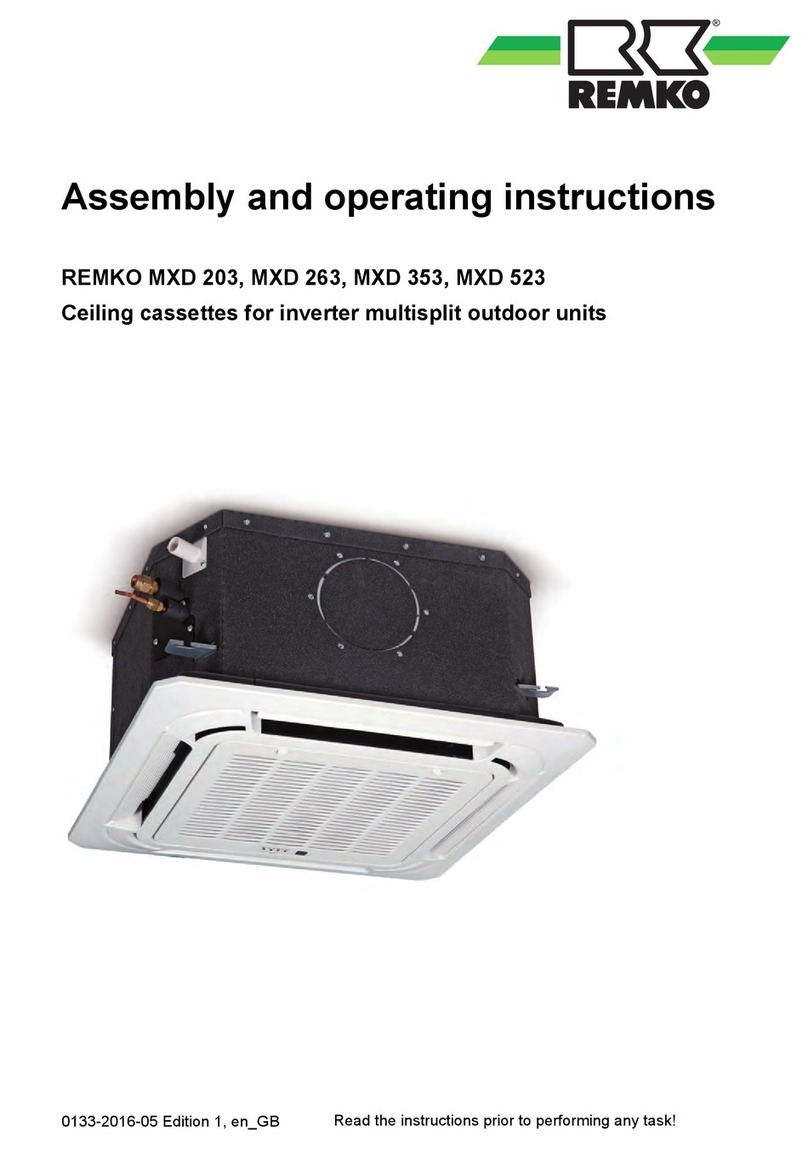
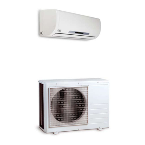
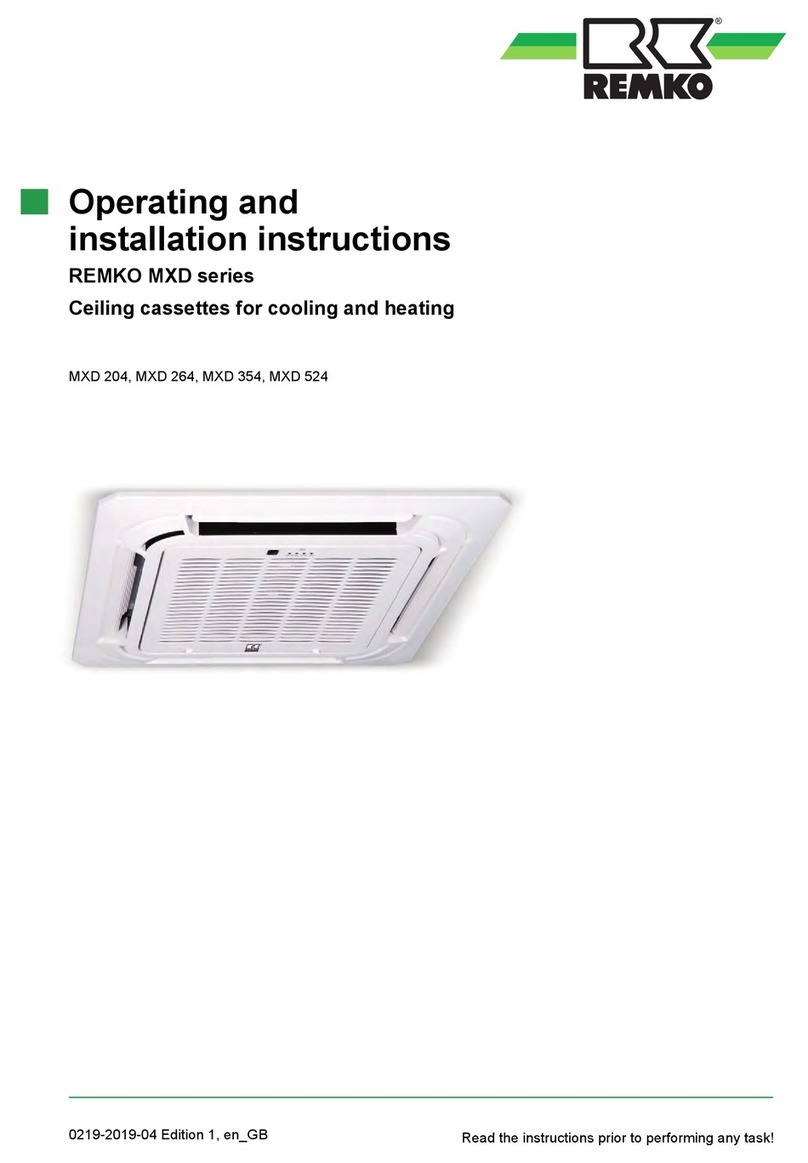
REMKO MXD Series User manual

Issue GB – W06
REMKO MXD
MXD 200, MXD 260, MXD 350, MXD 520
Ceiling cassette
Operation · Technology · Spare parts


Contents
Read these operating instructions carefully
before commissioning / using the device!
These instructions are an integral part of the system and must always
be kept near or on the device.
This operating manual is a translation of the German original, Version W-06
Subject to modifications; no liability accepted for errors or misprints!
Safety notes 4
Environmental protection and recycling 4
Warranty 4
Intended use 5
Transport and packaging 5
Equipment description 5
Combinations 6-7
Operation 8-14
shut-down 15
Care and maintenance 15-16
Troubleshooting and customer service 17-18
Installation instructions for qualified personnel 19
Installation 19-20
Condensate drain 20-21
Electrical connection 21
Electrical connection diagram and choice of unit 22
Electrical circuit diagram 22
Commissioning 23
Unit dimensions 23
Exploded view 25
Spare parts list 25
Technical data 26
EC-Declaration of Conformity 27
Made by REMKO
3

Safety notes
Carefully read the operating in-
structions before commissioning the
equipment for service. It provides
useful tips and information as
well as hazard warnings to prevent
injury or material damage . Fail-
ure to follow the directions in this
manual can result in endangerment
to persons, the environment and
the equipment itself and will void
any claims for liability.
■ Keep this manual and the refrig-
erant data sheet near the unit.
■ The unit should be set up and in-
stalled only by qualified person-
nel.
■ The set-up, connection, and op-
eration of the unit and its com-
ponents must be in accordance
with the operating conditions
stipulated in this manual and
comply with all applicable local
regulations.
■ Mobile units must be set up
securely on suitable surfaces and
in an upright position. Station-
ary units must be permanently
installed for operation.
■ Modification of equipment and
components supplied by REMKO
is not permitted and can cause
malfunctions.
■ Equipment and components
may not be operated in areas
where there is an increased risk of
damage. Observe the minimum
clearances.
■ The electrical supply is to be
adapted to the requirements of
the equipment.
■ The operational safety of equip-
ment and components is only
assured if they are fully as-
sembled and used as intended.
Safety devices may not be modi-
fied or bypassed.
■ Do not operate equipment or
components with obvious de-
fects or signs of damage.
■ All housing parts and openings
in the device, e.g. air inlets and
outlets, must be free of foreign
objects, fluids, or gases.
■ The equipment and components
must be kept an adequate dis-
tance from flammable, explosive,
combustible, abrasive and dirty
areas or atmospheres.
■ Touching some parts of the
equipment can result in burns or
other injury.
■ Installation, repair and mainte-
nance work may be carried out
only by authorised specialists.
Visual inspections and cleaning
can be performed by the opera-
tor as long as power is discon-
nected from the equipment.
■ To preclude any danger from
the equipment, take appropri-
ate hazard-prevention measures
when performing installation,
repair or maintenance work or
cleaning the equipment.
■ The equipment or components
are not to be exposed to any me-
chanical stresses, extreme levels
of humidity or direct sunlight.
Disposal of packaging
All products are packed for trans-
port in environmentally friendly
materials. Make a valuable contribu-
tion to reducing waste and sustain-
ing raw materials. Only dispose of
packaging at approved collection
points.
Disposal of equipment
and components
Only recyclable materials are used
in the manufacture of the devices
and components.
Help protect the environment by
ensuring that the devices or com-
ponents (for example batteries) are
not disposed in household waste,
but only in accordance with local
regulations and in an environmen-
tally safe manner, e.g. using certi-
fied firms and recycling specialists
or at collection points.
Warranty
Prerequisites for possible warranty
claims are that the ordering party or
their representative has completely
filled out the "warranty registration
card" and commissioning report
included with the unit at the time
when the equipment was pur-
chased and first put into operation
and returned it to:
REMKO GmbH & Co. KG and plac-
ing the unit in service.
The warranty conditions are listed
in the "General terms and condi-
tions". Furthermore, only the par-
ties to a contract can strike special
agreements beyond these condi-
tions. For this reason please contact
your contractual partner in the first
instance.
Environmental
protection
and recycling
REMKO MXD
4
The equipment is shipped in sturdy
transport packaging. Immediately
check the equipment on delivery
and make note of any damage or
missing parts on the delivery note
and inform the forwarding agent
and your contractual partner.
Warranty claims at a later date will
not be accepted.
Equipment description
Transport and
Packaging
The indoor unit on the split-design
combined room air conditioning
units serves to extract heat from
the indoor room being cooled. The
outdoor unit then expels this heat
to the outside.
If combined heating/cooling units
are operated as heaters, the heat
absorbed by the outdoor unit can
be discharged by the indoor unit
into the room being heated.
The unit is designed for installation
high up on indoor walls. Opera-
tion takes place using an infrared
remote control.
Stop valve
Mains cable
Schematic of refrigerant circuit
Connection
to suction
pipe
Connection to
injection line
Vaporiser Vaporiser fan
Refrigerant pipes are used to con-
nect the indoor unit to the outdoor
unit.
Outdoor
component
System layout
Condenser fan
Outdoor area
Injection line
Suction line
Control cable
Condensation line
Indoor area
Condensation line
Indoor unit
The indoor unit consists of a fin
vaporiser, vaporiser fan, controller
and condensation pan. The indoor
unit can be combined with REM-
KO outdoor units of series MVT
600/900/950/1050 DC with suf-
ficient cooling output. The outdoor
component is controlled via the
controller of the indoor unit.
Condensation pumps
are available as an accessory.
Intended use
Depending on the model, the
equipment and the additional
fittings with which it is equipped
is only intended to be used as an
air-conditioner for the purpose of
cooling or heating the air in an
enclosed room.
Different or additional use shall not
be classed as intended use. The
manufacturer/supplier assumes no
liability for damages arising from an
unintended use of the equipment.
The user bears the sole risk in such
cases.
Using the equipment as intended
also includes working in accord-
ance with the operating manual
and installation instructions and
complying with the maintenance
requirements.
5

MXD
200 MXD
260 MXD
350
One indoor unit
Combination 1 •
Combination 2 •
Combination 3 •
Two indoor units
Combination 4 • •
Combination 5 • •
Combination 6 • •
Combination 7 • •
Combination 8 • •
Outdoor unit MVT 600 DC
Combinations
MXD
200 MXD
260 MXD
350
One indoor unit
Combination 1 •
Combination 2 •
Combination 3 •
Two indoor units
Combination 4 • •
Combination 5 • •
Combination 6 • •
Combination 8 • •
Combination 9 • •
Three indoor units
Combination 13 • • •
Combination 14 • • •
Combination 15 • • •
Combination 16 • • •
Combination 17 • • •
Combination 18 • • •
Combination 19 • • •
Combination 20 • • •
Combination 21 • •
Outdoor unit MVT 900 DC
Indoor units MXD 200-520 can be combined with MVT series outdoor units.
The following combinations are possible.
Interior units
REMKO MXD
6

MXD
200 MXD
260 MXD
350 MXD
520
One indoor unit
Combination 1 •
Combination 2 •
Combination 3 •
Combination 4 •
Two indoor units
Combination 5 • •
Combination 6 • •
Combination 7 • •
Combination 8 • •
Combination 9 • •
Combination 10 • •
Combination 11 • •
Combination 12 • •
Combination 13 • •
Combination 14 • •
Three indoor units
Combination 15 • • •
Combination 16 • • •
Combination 17 • • •
Combination 18 • • •
Combination 19 • • •
Combination 20 • • •
Combination 21 • • •
Combination 22 • • •
Combination 23 • • •
Combination 24 • • •
Combination 25 • • •
Combination 26 • • •
Combination 27 • • •
Combination 28 • • •
Combination 29 •••
Four indoor units
Combination 31 • • • •
Combination 32 • • • •
Combination 33 • • • •
Combination 34 • • • •
Combination 35 • • • •
Combination 36 • • • •
Combination 37 • • • •
Combination 38 • • • •
Combination 39 • • • •
Combination 40 • • • •
Combination 41 • • • •
Combination 42 • • • •
MXD
200 MXD
260 MXD
350 MXD
520
One indoor unit
Combination 1 •
Combination 2 •
Combination 3 •
Combination 4 •
Two indoor units
Combination 5 • •
Combination 6 • •
Combination 7 • •
Combination 8 • •
Combination 9 • •
Combination 10 • •
Combination 11 • •
Combination 12 • •
Combination 13 • •
Combination 14 • •
Combination 15 • •
Combination 16 • •
Combination 17 • •
Combination 18 • •
Three indoor units
Combination 19 • • •
Combination 20 • • •
Combination 21 • • •
Combination 22 • • •
Combination 23 • • •
Combination 24 • • •
Combination 25 • • •
Combination 26 • • •
Combination 27 • • •
Combination 28 • • •
Combination 29 • • •
Combination 30 • • •
Combination 31 • • •
Combination 32 • • •
Combination 33 • • •
Combination 34 • • •
Combination 35 • • •
Combination 36 • • •
Four indoor units
Combination 37 • • • •
Combination 38 • • • •
Combination 39 • • • •
Combination 40 • • • •
Combination 41 • • • •
Combination 42 • • • •
Combination 43 • • • •
Combination 44 • • • •
Combination 45 • • • •
Combination 46 • • • •
Combination 47 • • • •
Combination 48 • • • •
Combination 49 • • • •
Combination 50 • • • •
Combination 51 • • • •
Combination 52 • • • •
Combination 53 • • • •
Combination 54 • • • •
Combination 55 • • • •
Outdoor unit MVT 950 DC Outdoor unit MVT 1050 DC
7

Operation
infrared remote control
The infrared remote control sends
the programmed settings over a dis-
tance of up to 6 m from the receiver
of the indoor unit. Data will only be
received correctly if the remote con-
trol is pointed at the receiver and no
objects obstruct the transmission
path.
First insert the batteries supplied on
delivery
(2 x type AAA) into the remote con-
trol. To do so, pull off the flap of the
battery compartment and insert the
batteries according to their polarity
(see markings).
The indoor unit is easily operated using the standard infrared remote control. The indoor unit beeps to acknowl-
edge the correct transmission of data. If it is not possible to program the indoor unit using the remote control,
it can also be manually operated.
Faults are indicated in code
(see chapter Troubleshooting
and Customer service).
!CAUTION
Immediately replace flat batter-
ies with a new set, otherwise
there is a risk of leakage. It is
recommended that the batteries
be removed if the equipment is
shut down for long periods.
NOTE
max. 6 m
Maximum distance
Manual operation
The indoor units can be started
manually.
Press the RESET button on the re-
ceiver unit of the cover to activate
automatic mode. In manual mode,
the following settings apply:
Cooling mode: 24 °C,
Fan speed AUTO
Heating mode: 26 °C,
Fan speed AUTO
Pressing any button on the infra-
red remote control interrupts
manual mode.
Display on the indoor unit
Unit for receiving signals
from the remote control
Operation
indicator
Alarm indicator
Display on the indoor unit
The lit LED indicators show the settings.
LED H red = high fan speed
LED M yellow = medium fan speed
LED L green = low fan speed
Timer
indicator
Fan
Defrost
REMKO MXD
8

"ECONOMIC RUNNING" button
Pressing this button will auto-
matically increase or decrease
the target temperature by 1 °C
within an hour in cooling and
heating mode respectively.
"AIR DIRECTION" button
With this button, the desired fin
position can be set. There are 5
positions and an oscillating func-
tion available.
"SWING" button
This button directly activates the
oscillating function of the fins
for better air distribution in the
room.
"TIMER ON/OFF" button
This button serves to program
the automatic activation time
for the device within the next
24 hours.
"CLOCK" button
This button opens the time pro-
gram.
"OK" button
This button transfers the pro-
grammed data to the indoor
unit.
"CANCEL" button
This button stops the timer pro-
gram once set.
"LOCK / RESET" button
(recessed buttons)
The left LOCK button prevents
subsequent operation, the right
RESET button resets the display.
Buttons on the remote control
"ON/OFF" button
Press this button
to start the unit.
"MODE" button
Use this button to
select the operating mode.
The indoor unit has 5 modes:
1. Automatic mode
In this mode, the unit works in
cooling or in heating mode.
2. Cooling mode
In this mode, the warm room
air is cooled to the
desired temperature.
3. Dehumidification mode
In this mode the room is mainly
dehumidified and the tempera-
ture setting is maintained.
4. Heating mode
In this mode, the warm air in the
room is heated up to the desired
temperature.
5. Circulation mode
In this mode, the air in the room
is recirculated.
Temperature selection is not
possible.
"Temp ▲ ▼ " button
This button is used to
select the desired temperature
between 17 - 30°C.
"FAN SPEED" button
Press this button to set the
desired fan speed. 4 settings
are available: automatic, high,
medium and low fan speed.
Buttons on the remote control
9

2i 10:49
TEMP CLOCK
SPEED
DRY
LOW
°
C
A symbol is shown on the display to indicate that the settings are being transferred.
Your air-conditioner is activated and deactivated by pressing the ON /
OFF button. The programmed settings and adjustment values from be-
fore the unit was turned off will appear on the display.
ON/OFF Button
ON/OFF ON/OFF
Use the MODE button to select between the individual operating modes. 5
modes are available:
1. Automatic automatic selection of cooling or heating mode
2. Cooling predominantly summer operating mode
3. Dehumidifying summer or winter operating mode
4. Heating predominantly winter operating mode
5. Air circulation only for circulation of air
MODE Button
MODE
Automatic Cooling Dehumidifying Heating Air circulation
MODE MODE MODE MODE
In automatic mode, the control system autonomously selects between
heating, cooling and air circulation modes. The nominal temperature can be
preselected and is then applied in automatic mode. The fan speed is auto-
matically adapted to the given circumstances.
AUTOMATIC MODE
COOLING
or
HEATING
The nominal temperature is
below the room temperature
▲
▼
OR
or
AIR CIRCULATION
The nominal temperature is
above the room temperature
The
p/q
buttons can be used to reduce and increase the desired nominal
temperature.
pq
Buttons
pq
Button functions
20
10:49
TEMP CLOCK
SPEED
COOL
LOW
°
C
20
10:49
TEMP CLOCK
SPEED
COOL
LOW
°
C
20
10:49
TEMP CLOCK
SPEED
COOL
LOW
°
C
20
10:49
TEMP CLOCK
SPEED
AUTO
AUTO
°
C
20
10:49
TEMP CLOCK
SPEED
COOL
LOW
°
C
20
10:49
TEMP CLOCK
SPEED
COOL
LOW
°
C
20
10:49
TEMP CLOCK
SPEED
COOL
LOW
°
C
2i 10:49
TEMP CLOCK
SPEED
COOL
LOW
°
C
2i 10:49
TEMP CLOCK
SPEED
COOL
LOW
°
C
2i 10:49
TEMP CLOCK
SPEED
FAN
LOW
2i 10:49
TEMP CLOCK
SPEED
AUTO
LOW
°
C
20
10:49
TEMP CLOCK
SPEED
COOL
LOW
°
C
2i 23
10:49 10:49
TEMP TEMP
CLOCK CLOCK
SPEED SPEED
AUTO AUTO
AUTO AUTO
°
C
°
C
2i 10:49
TEMP CLOCK
SPEED
HEAT
LOW
°
C
°
C
REMKO MXD
10

In cooling mode, the air in the room is cooled down to the set nominal
temperature. The desired room temperature is set with the ▲/▼buttons in
1 °C increments. If the room temperature is 1 °C above the selected nominal
temperature, the indoor unit starts to cool the air in the room. The inverter
controller checks the difference between the adjusted nominal temperature
and the actual room temperature. If there is a large difference, the cooling
output is very high. If the difference is smaller, a lower cooling output is
produced. This serves to maintain extremely even air discharge temperature
and room temperature.
If the adjusted room temperature is lower than approx. 2 °C, then the con-
trol system turns the cooling function off. To protect the compressor, the
controller only turns the cooling on again after a waiting period of 3 min-
utes.
Cooling MODE
COOLING
MODE
▲
▼
and
In dehumidifying mode, the room temperature is set to 24 °C. Due to the
low temperature of the refrigerant, the dew point of the air on the vaporiser
is lower. The excess moisture in the air is condensed by the vaporiser, the
room is dehumidified. The fan speed should be set to automatic in order to
achieve a maximum level of dehumidification. The fan speed is automati-
cally adapted to the given circumstances.
DEHUMIDIFYING MODE
DE-
HUMIDIFYING
MODE
30 secs
Nominal temperature
Nominal temperature -2°C
IU fan operation
OU fan operation
OU compressor operation
Actual temperature Start
Dehumidifying mode
Dehumidifying mode
Stop
Dehumidifying mode
Functional diagram
Operation
Stop
Low fan speed
▲
▼
AND
ON/OFF
MODE
MODE
20
10:49
TEMP CLOCK
SPEED
COOL
LOW
°
C
20
10:49
TEMP CLOCK
SPEED
DRY
AUTO
°
C
2i 10:49
TEMP CLOCK
SPEED
AUTO
LOW
2i 10:49
TEMP CLOCK
SPEED
COOL
LOW
°
C
2i 10:49
TEMP CLOCK
SPEED
FAN
LOW
°
C
22
10:49
TEMP CLOCK
SPEED
FAN
LOW
°
C
2i 10:49
TEMP CLOCK
SPEED
COOL
LOW
2i 10:49
TEMP CLOCK
SPEED
DRY
AUTO
°
C
24
10:49
TEMP CLOCK
SPEED
DRY
AUTO
°
C
24
10:49
TEMP CLOCK
SPEED
DRY
AUTO
°
C
> 6 mins> 3 mins
> 6 mins
30 secs 30 secs
Nominal temperature
Nominal temperature -2°C
IU fan operation
OU fan operation
OU compressor operation
Actual temperature Start cooling mode
Cooling mode
Stop cooling mode
Functional diagram
Operation
Stop
°
C
°
C
11

HEATING-
MODE
Heating mode operational sequence
> 6 mins> 3 mins
> 6 mins
30 secs 30 secs
Nominal temperature +5 °C
Nominal temperature +2 °C
IU fan operation
OU fan operation
OU compressor operation
Actual temperature Stop heating mode
Heating mode
Start heating mode
Functional diagram
Operation
Stop
Reverse flow valve
30 secs 30 secs
During the defrosting cycle, the indoor unit vaporiser fan and the outdoor
unit condenser fan are switched off.
After the cycle is concluded, the fans are switched to their
previous settings.
< 7 mins
Defrost period
15 secs 60 secs
IU fan operation
OU fan operation
OU compressor operation
Stop
Reverse flow valve
30 secs 30 secs
30 secs 3 mins
▲
▼
AND
MODE
In heating mode, you can heat the room in spring or autumn. The desired
room temperature is set with the ▲/▼buttons in 1 °C increments. If the
room temperature is 1 °C below the selected target temperature, the indoor
unit starts to heat the air in the room. The inverter controller checks the
difference between the adjusted nominal temperature and the actual room
temperature.
If there is a large difference, a higher cooling output is produced.
If there is a small difference, a lower cooling output is produced.
This serves to maintain the air discharge temperature and the room tem-
perature.
If the adjusted room temperature is still exceeded by approx. 2 °C, then
the control system turns the heating function off. To protect the compres-
sor, the controller only turns the heater on again after a waiting period of 3
minutes.
In heating mode, the indoor unit fan motor is switched on after a delay, in
order to prevent the discharge of cold air.
The fins on the outdoor unit could ice up at low outdoor temperatures.
Regular reversal of the cooling circuit results in a defrosting action.
The display shows "H1" during the defrosting period.
HEATING MODE
FAN
20
10:49
TEMP CLOCK
SPEED
HEAT
LOW
°
C
2i 10:49
TEMP CLOCK
SPEED
DRY
AUTO
°
C
2i 10:49
TEMP CLOCK
SPEED
HEAT
LOW
°
C
23
10:49
TEMP CLOCK
SPEED
HEAT
LOW
°
C
23
10:49
TEMP CLOCK
SPEED
HEAT
MED
°
C
Heating mode has priority!
If an indoor unit switches over
to heating mode, then cooling
is switched off for the other
indoor devices in cooling mode.
Cooling is not possible during
heating mode.
!CAUTION
Operation
REMKO MXD
12

The fan speed can be adjusted with this button. A selection can be made
between low, medium, high and automatic fan speed.
FAN SPEED Button
▲ ▲
In air circulation mode, the air in the room is only circulated.
The room temperature cannot be changed in this mode.
Cooling or heating mode is not activated.
AIR CIRCULATION MODE
AIR CIRCULATION
MODE
FAN
SPEED
FAN
SPEED
FAN
SPEED
FAN
SPEED
FAN
SPEED
This button activates a programme, which causes the nominal tempera-
ture in cooling mode to increase after one hour by 1°C and after two
hours by 2 °C. In heating mode, the target temperature is decreased by 1
°C after one hour by 2 °C after 2 hours.
The display indicator on the indoor unit goes out.
The TURBO function is used to activate the maximum fan speed.
ECONOMIC
RUNNING
ECONOMIC
RUNNING
ECONOMIC RUNNING button
Deactivated
The oscillating function of the air discharge fins can be adjusted with this
button. The air distribution in the room is improved by the swing function.
In order to adjust the aim of the air discharge fins to a particular direction,
the AIR DIRECTION button must be pressed briefly. In order to activate the
automatic swing function, the AIR DIRECTION button must be pressed for
longer than 2 seconds.
SWING and AIR DIRECTION Buttons
SWING SWING
Deactivated
20
20
20
20
10:49
10:49
10:49
10:49
TEMP
TEMP
TEMP
TEMP
CLOCK
CLOCK
CLOCK
CLOCK
SPEED
SPEED
SPEED
SPEED
FAN
FAN
FAN
FAN
LOW
LOW
LOW
LOW
°
C
°
C
°
C
°
C
2i 10:49
TEMP CLOCK
SPEED
HEAT
LOW
°
C
2i 10:49
TEMP CLOCK
SPEED
HEAT
AUTO
°
C
2i 10:49
TEMP CLOCK
SPEED
HEAT
AUTO
°
C
2i 10:49
TEMP CLOCK
SPEED
HEAT
AUTO
°
C
2i 10:49
TEMP CLOCK
SPEED
HEAT
AUTO
°
C
2i 10:49
TEMP CLOCK
SPEED
HEAT
AUTO
°
C
2i 10:49
TEMP CLOCK
SPEED
HEAT
AUTO
°
C
2i 10:49
TEMP CLOCK
SPEED
HEAT
LOW
°
C
2i 10:49
TEMP CLOCK
SPEED
HEAT
MED
°
C
2i 10:49
TEMP CLOCK
SPEED
HEAT
HIGH
2i 10:49
TEMP CLOCK
SPEED
FAN
LOW
°
C
2i 10:49
TEMP CLOCK
SPEED
FAN
MED
°
C
°
C
13

The activation and switch-off time can be programmed with this button.
The timer is activated/deactivated by means of pressing the timer on and
thetimeroffbutton.ThetimersymbolONTIMERorOFFTIMERappears.The
desired turn on or turn off time is set by pressing the TIME ADJUST button.
Pressing a TIME ADJUST arrow button adjusts the time in 10 min. intervals.
Pressing both TIME ADJUST arrow buttons enables the time to be set more
quickly.
When the programmed time has been reached, the device is automatically
turned on or off. If the indoor unit is automatically switched on, then the
mode, temperature and fan speed for the last setting is reactivated.
Pressing the OK button serves to store the selected TIMER setting.
The on and off time can be deleted before the timer elapses by pressing the
CANCEL button. The timer display on the indoor unit goes out.
CLOCK button
TIMER button TIMER ON / OFF
TIMER ON button - activation delay
Activation delay
TIMER OFF button - switch-off delay
CANCEL - delete timer program
Switch-off delay
Time stored
TIMER
ON
TIMER
ADJUST
TIMER
ADJUST
TIMER
ADJUST OK
TIMER
OFF
CANCEL
CLOCK
20
10:49
18:45
22:30
TEMP CLOCK
SPEED
FAN
LOW
°
C
TIMER ON
TIMER OFF
20
10:49
18:45
22:30
TEMP CLOCK
SPEED
FAN
LOW
°
C
TIMER ON
TIMER OFF
2i
10:49
TEMP CLOCK
SPEED
HEAT
LOW
°
C
2i
10:49
TEMP CLOCK
SPEED
HEAT
LOW
°
C
2i
10:49
TEMP CLOCK
SPEED
HEAT
LOW
°
C
2i
10:49
TEMP CLOCK
SPEED
HEAT
LOW
°
C
2i
10:49
TEMP CLOCK
SPEED
HEAT
LOW
°
C
2i 10:49
TEMP CLOCK
SPEED
HEAT
LOW
°
C
18:45
TIMER ON
06:30
06:30 06:30
06:30
12:30 17:30
17:30
TIMER ON
10:49
TEMP CLOCK
SPEED
HEAT
LOW
°
C
06:30
TIMER ON
2i
10:49
TEMP CLOCK
SPEED
HEAT
LOW
°
C
2i
i0:49
TEMP CLOCK
SPEED
HEAT
LOW
°
C
2i
i0:49
TEMP CLOCK
SPEED
HEAT
LOW
°
C
2i
i5:50
TEMP CLOCK
SPEED
HEAT
LOW
°
C
2i
i5:50
TEMP CLOCK
SPEED
HEAT
LOW
°
C
TIMER ON TIMER ON
TIMER ON
TIMER OFF TIMER OFF
TIMER OFF
The current time can be adjusted with this button. If the clock button is
pressed for longer than 3 secs, the time can be set with the TIME ADJUST
button. Store
Timer deleted
2i
REMKO MXD
14

Regular care and observation
of some basic points will ensure
trouble-free operation and a long
service life.
Care and maintenance
Prior to performing any work,
ensure the equipment is iso-
lated from the voltage supply
and secured to prevent acci-
dental switch-on!
!CAUTION
Temporary shut-down
1. Allow the indoor unit to run for
2 to 3 hours in air circulation
mode or in cooling mode at the
maximum temperature setting
in order to remove any residual
moisture from the unit.
2. Shut down the system using
the remote control.
3. Switch off the voltage supply to
the unit.
4. Check the unit for visible signs
of damage and clean it as
described in the chapter "Care
and maintenance".
Permanent shut-down
Ensure that equipment and com-
ponents are disposed of
in accordance with the applicable
regulations, e.g. through author-
ised disposal and recycling special-
ists or at collection points.
REMKO GmbH & Co. KG or your
contractual partner will be pleased
to provide a list of certified firms
near you.
Shut-down
Care
■
Ensure the unit is protected
against dirt, mould and other
deposits.
■
Clean the unit using a damp
cloth. Do not use any caustic,
abrasive or solvent-based clean-
ing products. Do not use a jet of
water.
■
Clean the fins on the unit prior to
long shutdown periods.
Maintenance
■ We recommend a maintenance
contract with annual mainte-
nance interval with an appropri-
ate specialist company.
This ensures the operational
reliability of your system!
TIP
Type of task
Checks/Maintenance/Inspections
Commissioning
Monthly
Half-yearly
Yearly
General • •
Measure voltage and current • •
Check function of compressor/fans • •
Dirt on condenser/vaporiser • •
Check refrigerant fill quantity • •
Check condensation drain • •
Test insulation • •
Check moving parts • •
Sealing test for refrigerant circuit • • 1)
Statutory regulations require
an annual leak test for the
refrigerant circuit in relation
to the refrigerant medium fill
level. Inspection and docu-
mentation is to be carried out
by specialist technicians.
NOTE
Cleaning the cover
of the indoor unit
1. Disconnect the supply voltage
to the equipment.
2. Open and fold down the air
inlet guard on the cover. The
filter is held in place by the flaps
screwed in at the side of the
guard (Page 16, Fig. 1).
3. Clean the guard and cover using
a soft, damp cloth.
4. Switch the supply voltage back
on.
15
1) See note

2 Cleaning using a vacuum cleaner
Air filter for indoor unit
Clean the air filter at intervals of
no more than two weeks. Reduce
this interval if the air is especially
dirty.
Cleaning the filter
1. Disconnect the supply voltage
to the equipment.
2. Open and fold down the air
inlet guard on the cover. The
filter is held in place by the flaps
screwed in at the side of the
guard (Fig. 1).
3. Tilt the filter to lift it out (Fig. 1).
4. Clean the filter using a normal
vacuum cleaner (Fig. 2).
To do so, turn the dirty side
upward.
5. Dirt can also be removed by
carefully cleaning with lukewarm
water and mild cleaning agents.
To do so, turn the dirty side
downward (Fig. 3).
6. When using water, allow the
filter dry out properly in air
before replacing it in the unit.
7. Carefully insert the filter. Make
sure it is seated correctly.
8. Close the cover as described
above but in reverse order.
9. Switch the supply voltage back
on.
10.
Switch the unit on again.
Cleaning the
condensation pump
The indoor unit includes a built-in
condensation pump, for pump-
ing the condensation to a drain at
a higher level.
The pump is more or less mainte-
nance free. The condensation pipes
should be checked for dirt at regular
intervals. Clean them as required.
If an external pump is also used,
observe the maintenance and care
instructions given in the separate
operating manual.
1 Pull out the filter
3
Cleaning with lukewarm water
REMKO MXD
16

Troubleshooting and customer service
Malfunctions
The equipment and components are manufactured using state-of-the-art production methods and tested sev-
eral times to verify their correct function. If malfunctions should occur, please check the functions as detailed in
the list below. For installations with an indoor unit and outdoor unit, refer to the chapter "Troubleshooting and
customer service" in both manuals. Please inform your dealer if the unit is still not working correctly after all the
functional checks have been performed!
Fault Possible cause Checks Remedy
The unit does not start
or switches itself off
off.
Poweroutage,undervoltage,defec-
tive mains fuse / main switch in off
position
Are all other electrical installations
functioning correctly? Check voltage if necessary wait
until turned on again.
Damaged mains cable Are all other electrical installations
functioning correctly? Repair by a specialist
Wait time after switching on is too
short Have approx. 5 minutes
elapsed since the restart? Schedule longer waiting periods
Temperature outside operating
range.
Are the fans in the indoor unit
and outdoor component working
correctly?
Take into account the temperature
range for the indoor unit and out-
door component
Electrical surges caused by thun-
derstorms Have there been lightning strikes in
the area recently?
Switch off the mains breaker and
switch it back on. Have it checked
by a specialist
Fault in external condensation
pump Did the pump shut down due to
a fault? Check and if necessary clean the
pump
The unit does not respond
to the remote control
Transmission distance too far /
receiver affected by interference Does the indoor unit beep when
pressing a button? Reduce the distance to less than 6
m or change position
Defective remote control Is the unit running in manual mode? Replace the remote control
Receiver or transmitter unit ex-
posed to excessive solar radiation Does it function correctly in the
shade? Place the receiver & transmitter unit
in the shade
Electromagnetic fields are interfer-
ing with transmission Does it function when switching off
possible sources of interference? Signal is not transmitted when
interference sources are operational
Button in remote control jammed /
two buttons pressed at same time Does the “Send” symbol appear
on the display? Release the button / press only one
button
Batteries in remote control are flat Have new batteries been inserted?
Is the display incomplete? Insert new batteries
The unit is running with
reduced or without
cooling / heating output
Filter is unclean / air inlet / outlet
blocked by foreign objects Have the filters been cleaned? Clean the filters
Windowsanddoors open. Heating/
cooling loads increased Have there been any structural /
usage-related changes? Close windows and doors / install
additional units
Neither cooling nor heating mode
has been set Does the cooling symbol appear on
the display? Correct the settings for the unit
Fins on outdoor component
blocked by foreign objects
Is the fan on the outdoor com-
ponent running? Are the fins
unobstructed?
Check the fan or winter controller,
reduce the air resistance
Leaking refrigerant circuit Are there signs of frost on the fins
of the indoor unit? Repair by specialist
Outdoor component iced up
Check outdoor component.
Has the cassette sensor on the
outdoor component been correctly
positioned?
De-ice and fit the sensor at the
point where the most ice forms
Condensation discharge
on unit
Drainage pipe on collection con-
tainer clogged / damaged Can the condensation drain off
without any obstruction? Clean the drainage pipe and collec-
tion container
Faulty external condensation pump
or float Is the collection tray full of water
and the pump not running?
Call out a specialist to replace the
pump
Condensation has not drained away
and has collected in the condensa-
tion line
Is there a steady fall on the con-
densation pipe? Check there is no
blockage in the pipe.
Ensure there is a fall when laying
the condensation pipe and clean
the pipe.
Condensation does not drain off
Are the condensation lines un-
blocked and laid on a slope? Are the
condensation pump and float switch
functioning correctly?
The condensation line must have
a fall. If necessary, clean the pipe.
A faulty condensation pump and
float switch should be replaced.
Float is stuck or jammed due to
excessive dirt. Are the LEDs on the receiver unit of
the indoor unit flashing?
Should be cleaned by specialist firm
17

Fault indication by flashing code
REMKO MXD
18
LED
Operation
LED
Timer
LED
Defrost
LED
Alarm
OU dis-
play Cause Required action
flashes - Sensor air circulation faulty / tripped Check resistance
flashes - Sensor on vaporiser faulty / tripped Check resistance
flashes E7 Communication error between PCBs
OU & IU
Check electrical connection
leads
flashes flashes E0 EEPROM error Check EEPROM
flashes On - Inverter module shutdown
flashes - Condensation pump float switch faulty/
tripped Contact specialist dealer
flashes On E4 Outdoor temp sensor on OU tripped Check resistance and tem-
perature on sensor
flashes On On E5 Surge voltage on outdoor unit Check power supply
flashes On P0 Excess temperature in compressor Allow compressor to cool
flashes On On - Mode conflict Switch system off
flashes flashes flashes P3 OU power consumption too high Check power consumption

Installation instructions for qualified personnel
Important notes prior to
installation
Minimum clearances
Observe the minimum clearances to
allow access for maintenance,
repair work and for
optimum air distribution.
Minimum clearances
All dimensions are given in mm
For installation of the entire sys-
tem, observe the operating instruc-
tions of the indoor unit and the
outdoor unit.
■
Transport the unit in its original
packaging as close as possible
to the installation location.
This avoids transportation dam-
age.
■
Check the contents of the
packaging for completeness
and check the unit for visible
transport damage.
Immediately notify any de-
ficiencies to the contractual
partner and forwarding agent.
■
Lift the unit at the corners and
not by the refrigerant or con-
densation connections.
■
The refrigerant pipes (injec-
tion and suction pipe), valves
and connections to make them
tight against vapour diffusion.
If necessary, also insulate the
condensation line.
■
Select an installation location
which allows air to freely flow
through the inlet and outlet (see
section "Minimum clearances")
■
Do not install the unit in the
immediate vicinity of devices
with intensive thermal radia-
tion. Installation near sources of
thermal radiation reduces the
output of the unit.
■
Install the refrigerant pipes from
the indoor unit to the outdoor
unit.
■
Seal off open refrigerant lines
with suitable caps or adhesive
strips to avoid the infiltration
of moisture and never kink or
compress the refrigerant pipes.
■
Only use the union nuts for the
refrigerant pipes included in
the delivery, and remove them
shortly before connecting the
refrigerant pipes.
.
■
Establish all electrical connec-
tions in accordance with the rel-
evant DIN and VDE standards.
■
Always ensure electrical cables
are properly connected to the
terminals, otherwise there is
a risk of fire.
■
Service openings should be pro-
vided in the suspended ceiling
to allow maintenance access to
the control box.
Installation material
The indoor unit is fastened using
a wall brace and 4 bolts (provided
by the customer).
In order to complete the installa-
tion, use the supplied installation
material. Appropriate dowels, trap-
ezoidal sheet metal supports, steel
profiles, fixing clips for refrigerant
and condensation pipes (as well as
laying ducts) and connection fit-
tings for condensation pipes must
also be provided.
Selection of the installation
location
The indoor unit is designed for
horizontal mounting in suspended
ceilings with Euroraster dimen-
sions. It can also be installed in
other types of suspended ceilings
with different dimensions.
Take into account the installation
height of the equipment.
1000
1000 1000
1000
Installation
Installation may only be per-
formed by authorised specialists.
NOTE
Unit installation
The unit is mounted on four thread-
ed rods with the cover face down.
Take into account the ceiling grid
and any other installations.
1. Use the dimensions of the ceil-
ing cassette to mark the fixing
points for the threaded rods on
structural parts approved to sup-
port the static load, and above
the suspended ceiling.
19

The units are factory filled with
dry nitrogen to check for leaks.
The pressurised nitrogen is
released when the union nuts
are loosened.
!CAUTION
Condensate drain
If the temperature falls below the
dew point, condensation will form
on the cooling fins during cooling
mode.
A collection tray together with
a condensation pump and float
switch are fitted as standard below
the cooling fins. Should the float
switch trip a protective shutdown
due to inadequate removal of the
condensation, the pump will switch
on immediately and run on for ap-
prox. three minutes.
■
The condensation pipe should
have a fall of min. 2 %. This is the
responsibility of the customer.
If necessary, fit vapour diffusion
proof insulation.
■
If the level of the condensation
pipe on the unit is above that of
the outlet, route the pipe verti-
cally upwards (max. see P. 21)
and then with a fall to the drain.
■
Lead the condensation line
freely to the run-off line. If the
condensation runs directly into
a sewer pipe, fit a trap to prevent
any unpleasant odours.
■
When operating the unit at
outdoor temperatures below
4 °C, ensure the condensation
pipe is laid to protect it against
frost.
If necessary, fit supplementary
pipe heating.
■
Once the pipe has been
laid, check the condensation
drains off and
permanently seal it.
Connecting the
refrigerant lines
The refrigerant lines on the MXD
200-520 should be connected by
the customer to the centre of the
long side.
It may be necessary to fit a reduc-
ing or extending adapter to the
indoor units. These fittings are
included with the indoor unit as an
accessory kit. Once installed, the
connections should be sealed to
prevent vapour diffusion.
5 Hooking in the unit
Structural component
2. Fit the indoor unit onto the
threaded rods and use the
lower nuts to level the unit
(Figure 5).
3. Ensure a clearance of 35 mm
from the ceiling. Connect the
refrigerant pipes, electrical
cables and condensation pipe
to the indoor unit as described
below.
4. Check that the unit is level.
5. The final task is to tighten the
counternuts and attach the
cover.
Riser pipe too far away
No fall
Condensation connection - Wrong!
615
280
MXD 200-520
Unit attachment
REMKO MXD
20
This manual suits for next models
4
Table of contents
Other REMKO Air Conditioner manuals

REMKO
REMKO RXD 260 User manual

REMKO
REMKO SKT 521 User manual

REMKO
REMKO RVT Series User manual

REMKO
REMKO MXD 204 User manual

REMKO
REMKO MXD 203 User manual

REMKO
REMKO RKW 13 W User manual

REMKO
REMKO MVT 602 DC User manual

REMKO
REMKO RVD 351DC User manual

REMKO
REMKO MKT 291 User manual

REMKO
REMKO MKT 240 User manual

REMKO
REMKO RXT Series User manual

REMKO
REMKO ML 263 DC User manual

REMKO
REMKO RVD 351DC User manual

REMKO
REMKO RKL 490 DC User manual

REMKO
REMKO MVD Series User manual

REMKO
REMKO ATY Series User manual

REMKO
REMKO ML Series User manual

REMKO
REMKO BL Series User manual

REMKO
REMKO RKL DC Series User manual

REMKO
REMKO ATY DC Series User manual