Renaissance
Cooking Systems
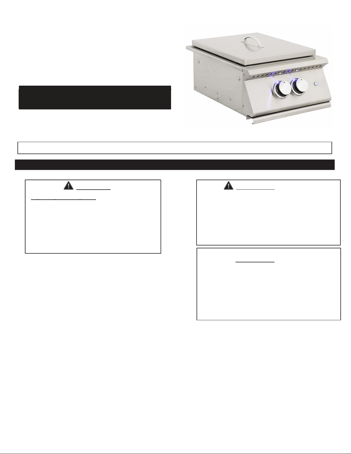
PREMIER PROBURNER
MODEL # RJCSB3A Use Liner Jacket LJRJCSB3A
INSTALLATION AND OPERATING
INSTRUCTIONS
INSTALLER: Leave these instructions with consumer.
CONSUMER: READ & retain for future reference.
Important: READ THESE INSTRUCTIONS CAREFULLY BEFORE BEGINNING INSTALLATION
SAFETY WARNINGS &CODES
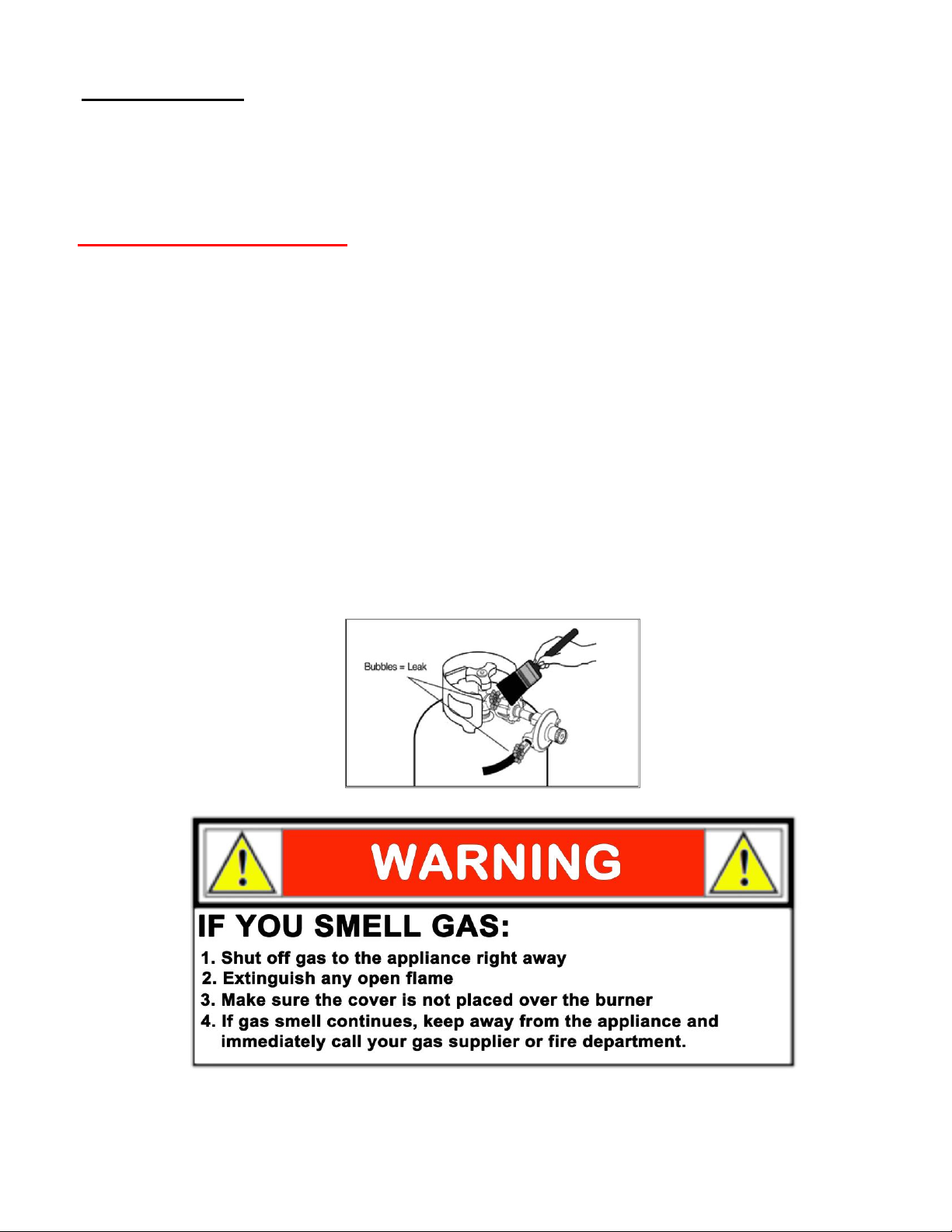
DANGER
IF YOU SMELL GAS:
1. Shut off the gas to the appliance.
2. Extinguish any open flame.
3. Open lid to vent.
4. If odor continues, keep away from the
appliance, and immediately call your
gas supplier or fire department.
WARNING
1. Do not store or use gasoline or other
flammable vapors and liquids in the
vicinity of this or any other appliance.
2. Apropane cylinder not connected for use
shall not be stored in the vicinity of this
or any other appliance with flame.
CODE AND SUPPLY REQUIREMENTS: This pro
burner must be installed in accordance with local codes
and ordinances, or, in the absence of local codes, with
either the latest National Fuel Gas Code (ANSI Z223.1/
NFPA 54), and Natural Gas and Propane Storage and
Handling Installation Code (CSA-B149.1).
This appliance and its individual shutoff valves must
be disconnected from the gas supply piping system
when testing the system at pressures in excess of
½psig (3.5 kPa).
This appliance must be isolated from the gas supply
piping system by closing its individual manual
shut-off valvesduring any pressure testing of the
gas supply system at pressures up to and including
½psig (3.5 kPa).
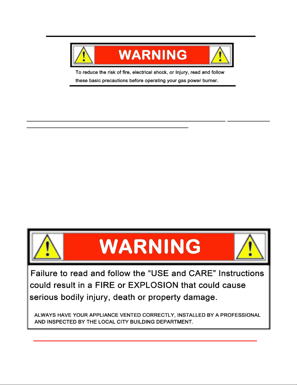
WARNING
Improper installation, adjustment, alteration,
service, or maintenance can cause injury or
property damage. Refer to this manual. For
assistance or additional information consult
aqualified professional installer, service
agency, or the gas supplier.
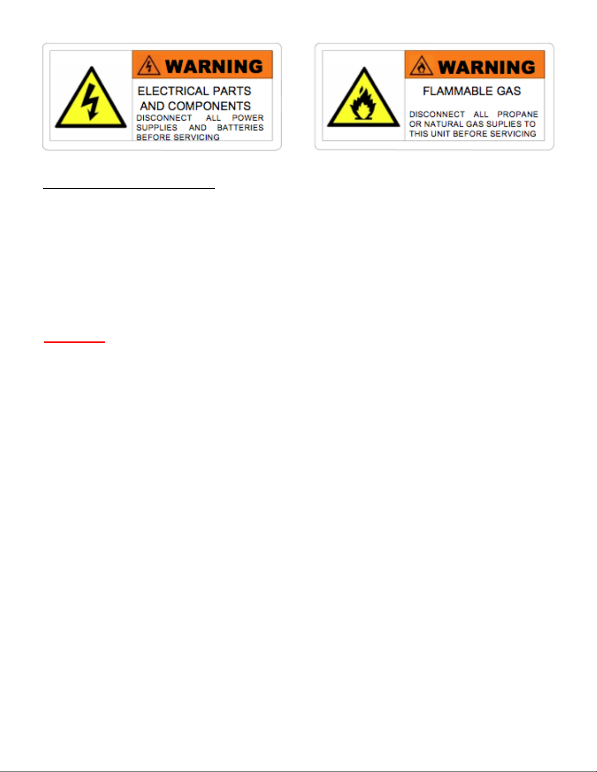
All electrical outlets in the vicinity of the pro
burner must be properly grounded in
Accordance with local codes or, in the
absence of local codes, with the National
Electrical Code, ANSI/NFPA 70, or the
Canadian Electrical Code, CSA C22.1,
whichever is applicable.
Keep all electrical supply cords and fuel
supply hoses away from any heated surface
at all times.