RenewAire EV450IN Owner's manual

MODEL SHOWN: HE1.5XRT
ECM MOTOR SUPPLEMENTAL MANUAL
LIGHT COMMERCIAL UNITS
ECM MOTORS FOR:
EV450 (IN & RT)
HE1X (IN & RT)
HE1.5X (IN & RT)
RENEWAIRE.COM
MODEL SHOWN: HE1XIN
MODEL SHOWN: EV450IN

ECM MOTORS
RENEWAIRE.COM ECM MOTOR SUPPLEMENTAL MANUAL 1.800.627.4499
2
Product info ......................... 3-7
Installation......................... 8-12
Start-up............................13-14
Notes .................................... 15
TABLE OF CONTENTS
ABOUT RENEWAIRE
For over 30 years, RenewAire has been a pioneer in enhancing indoor air quality (IAQ) in commercial
and residential buildings of every size. This is achieved while maximizing sustainability through our fifth-
generation, static-plate, enthalpic-core Energy Recovery Ventilators (ERVs) that optimize energy efficiency,
lower capital costs via load reduction and decrease operational expenses by minimizing equipment needs,
resulting in significant energy savings. Our ERVs are competitively priced, simple to install, easy to use and
maintain and have a quick payback. They also enjoy the industry’s best warranty with the lowest claims due
to long-term reliability derived from innovative design practices, expert workmanship and Quick Response
Manufacturing (QRM).
As the pioneer of static-plate core technology in North America, RenewAire is the largest ERV producer in the
USA. We’re committed to sustainable manufacturing and lessening our environmental footprint, and to that
end our Madison, WI plant is 100% powered by wind turbines. The facility is also one of the few buildings
worldwide to be LEED and Green Globes certified, as well as having achieved ENERGY STAR Building status.
In 2010, RenewAire joined the Soler & Palau (S&P) Ventilation Group in order to provide direct access to the
latest in energy-efficient air-moving technologies. For more information, visit: renewaire.com.

ECM MOTORS
3
1.800.627.4499 ECM ECM MOTOR SUPPLEMENTAL MANUAL RENEWAIRE.COM
When an external 10VDC source control is used
the maximum distance between ECM motor and
10VDC source control cannot exceed 33 feet (10m).
CAUTION
ECM MOTORS
RenewAire’s light commercial units are offered
with optional electronically commutated motors
(ECM). ECM motors have higher efficiencies with
considerable energy savings over a standard
permanent split capacitor motor. The ECM motors
offered in RenewAire ERVs are constant torque
with a variety of speed control options. The motors
operate at fixed speed or variable speed with
speed inputs from fixed resistors, potentiometer,
or 0-10Vdc analog signal.
OPERATING CONTROLS
A wide variety of low voltage (24VAC) control
schemes may be selected to meet the ventilation
needs of the facility. These include time clock,
occupancy sensor, carbon dioxide sensor, and
others. Building Management Systems (BMS) may
also control the unit with external control by others.
ABOUT ECM MOTORS
PRODUCT INFO
ELECTRICAL SPECIFICATIONS
ELECTRICAL RATINGS FOR ECM UNITS
Phase (unit) Input
Voltage
FLA
(motor) MCA (unit) MOPD (unit)
EV450 1
115 VAC 8.1 10.1 15
208-230 VAC 4.8 6.0 15
HE1X 1
115 VAC 8.1 18.2 25
208-230 VAC 4.8 10.8 15
HE1.5X 1
115 VAC 8.0 18.0 20
208-230 VAC 6.2 14.0 15

ECM MOTORS
RENEWAIRE.COM ECM MOTOR SUPPLEMENTAL MANUAL 1.800.627.4499
4
ECM OPTION
OPERATING RANGES
PRODUCT INFO
F1 EV450IN ECM
F2 EV450RT ECM
0.00
0.25
0.50
0.75
1.00
1.25
200 250 300 350 400 450 500 550 600
External Static Pressure (in. w.g.)
Airflow (cfm)
EV450-IN ECM
74
75
76
80
80
160
171
177
183
188
198
269
284
299
307
315
328
403
410
427
436
447
449
500 (Watts)
506
520
521
515
487
0.00
0.25
0.50
0.75
1.00
1.25
200 250 300 350 400 450 500 550 600
External Static Pressure (in. w.g.)
Airflow (cfm)
EV450-RT ECM
514 (Watts)
415
289
174
77
520
521
516
502
470
426
438
447
451
436
301
310
317
324
337
180
186
191
196
204
78
80
82
85
EV450-IN ECM
Sample Points
CFM ESP* Watts
229 0.07 75
321 0.16 171
395 0.25 284
458 0.34 410
491 0.40 506
209 0.20 80
289 0.43 188
350 0.67 315
396 0.90 447
416 1.00 515
EV450-RT ECM
Sample Points
CFM ESP* Watts
217 0.07 78
305 0.16 180
375 0.25 301
435 0.34 426
467 0.40 520
200 0.20 85
274 0.43 196
332 0.67 324
376 0.90 451
395 1.00 502
Note: Watts is for the entire unit.
*Inches Water Column
Note: Watts is for the entire unit.
*Inches Water Column

ECM MOTORS
5
1.800.627.4499 ECM ECM MOTOR SUPPLEMENTAL MANUAL RENEWAIRE.COM
ECM OPTION
OPERATING RANGES
PRODUCT INFO
F3 HE1XIN ECM (H or V)
F4 HE1XRT ECM
0.00
0.25
0.50
0.75
1.00
1.25
1.50
1.75
250 500 750 1000 1250
External Static Pressure (in. w.g.)
Airflow (cfm)
HE1X-IN ECM (H or V)
85
97
89
148
150
153
156
160
164
173
273
300
322
340
359
386
392
560
564
572
583
599
643
655
818
827
839
852
871
911
918
1029 (Watts)
1042
1056
1068
1075
1029
992
0.00
0.25
0.50
0.75
1.00
1.25
1.50
1.75
250 500 750 1000 1250
External Static Pressure (in. w.g.)
Airflow (cfm)
HE1X-RT ECM
87
99
91 151
153
156
159
163
168
177
298
321
339
354
368
380
397
564
572
582
594
612
630
665
828
838
851
864
881
898
921
1041 (Watts)
1053
1065
1073
1074
1061
966
HE1X-IN ECM
Sample Points
CFM ESP* Watts
324 0.04 86
446 0.07 150
647 0.15 300
794 0.24 564
929 0.33 827
1019 0.41 1042
300 0.11 91
406 0.20 160
579 0.42 359
713 0.65 599
828 0.89 871
883 1.00 1075
HE1X-RT ECM
Sample Points
CFM ESP* Watts
314 0.04 88
433 0.07 153
627 0.15 321
770 0.24 572
901 0.33 838
988 0.41 1053
291 0.11 93
394 0.20 163
561 0.42 368
692 0.65 612
803 0.89 881
857 1.01 1074
Note: Watts is for the entire unit.
*Inches Water Column
Note: Watts is for the entire unit.
*Inches Water Column

ECM MOTORS
RENEWAIRE.COM ECM MOTOR SUPPLEMENTAL MANUAL 1.800.627.4499
6
ECM OPTION
OPERATING RANGES
PRODUCT INFO
F5 HE1XRTC ECM
Unit Tied Into Separate Ducts
F6 HE1XRTC ECM
Unit Tied Into Air Handler
0.00
0.25
0.50
0.75
1.00
1.25
250 375 500 625 750 875 1000 1125 1250
External Static Pressure (in. w.g.)
Airflow (cfm)
HE1X-RTC ECM
Unit Tied Into Separate Ducts
890 watts
900
806
516
694
718
654
471
372
250
131
94
444
276
139
89
470
277
140
443
249
137
89
HE1X-RTC EA EC
-1.25
-1.00
-0.75
-0.50
-0.25
0.00
500 625 750 875 1000 1125 1250
External Static Pressure (in. w.g.)
Airflow (cfm)
HE1X-RTC ECM
Unit Tied into Air Handler
1040 (Watts)
866
559297
1050
1060
755
907
595
333
851
562
331
630
451
296

ECM MOTORS
7
1.800.627.4499 ECM ECM MOTOR SUPPLEMENTAL MANUAL RENEWAIRE.COM
PRODUCT INFO
F7 HE1.5XIN ECM (H or V)
F8 HE1.5XRT ECM
0.00
0.25
0.50
0.75
1.00
1.25
1.50
1.75
375 500 625 750 875 1000 1125 1250 1375 1500 1625
External Static Pressure (in. w.g.)
Airflow (cfm)
HE1.5X-IN ECM
190
189
188
187
185
183
178
314
314
313
312
310
306
296
500
502
502
501
498
493
475
730
735
739
739
735
727
698
1006 (Watts)
1015
1021
1022
1017
1006
965
0.00
0.25
0.50
0.75
1.00
1.25
1.50
1.75
375 500 625 750 875 1000 1125 1250 1375 1500 1625
External Static Pressure (in. w.g.)
Airflow (cfm)
HE1.5X-RT ECM
189
188
187
185
182
179
314
313
312
309
304
298
283
501
502
501
497
489
478
451
735
739
738
733
722
703
658
1015 (Watts)
1021
1022
1015
1000
973
907
ECM OPTION
OPERATING RANGES
HE1.5X-IN ECM
Sample Points
CFM ESP* Watts
630 0.07 189
807 0.12 314
1014 0.20 502
1222 0.28 735
1430 0.39 1015
513 0.20 185
656 0.33 310
825 0.52 498
994 0.74 735
1163 1.01 1017
HE1.5X-RT ECM
Sample Points
CFM ESP* Watts
593 0.07 188
760 0.12 313
955 0.20 502
1151 0.29 739
1347 0.39 1021
453 0.20 182
577 0.33 304
725 0.51 489
874 0.74 722
1026 1.01 1000
Note: Watts is for the entire unit.
*Inches Water Column
Note: Watts is for the entire unit.
*Inches Water Column

ECM MOTORS
RENEWAIRE.COM ECM MOTOR SUPPLEMENTAL MANUAL 1.800.627.4499
8
PLANNING
YOUR INSTALLATION
INSTALLATION
To avoid motor bearing damage
and noisy and/or unbalanced
impellers, keep drywall spray,
construction dust, etc., out of unit.
CAUTION
1. Before servicing or cleaning the unit, switch
power off at disconnect switch or service panel
and lockout/tag-out to prevent power from being
switched on accidentally. More than one discon-
nect switch may be required to de-energize the
equipment for servicing.
2. This installation manual shows the suggested
installation method. Additional measures may be
required by local codes and standards.
3. Installation work and electrical wiring must be
done by qualified professional(s) in accordance
with all applicable codes, standards and
licensing requirements.
4. Any structural alterations necessary for instal-
lation must comply with all applicable building,
health, and safety code requirements.
5. This unit must be grounded.
6. Sufficient air is needed for proper combustion and
exhausting of gases through the flue (chimney) of
fuel burning equipment that might be installed in
the area affected by this equipment. If this unit
is exhausting air from a space in which chim-
neyvented fuel burning equipment is located,
take steps to assure that combustion air supply
is not affected. Follow the heating equipment
manufacturer’s requirements and the combustion
air supply requirements of applicable codes and
standards.
7. Use the unit only in the manner intended by the
manufacturer. If you have questions, contact
the manufacturer.
8. This unit is intended for general ventilating only.
Do not use to exhaust hazardous or explosive
materials and vapors. Do not connect this unit to
range hoods, fume hoods or collection systems
for toxics.
9. When cutting or drilling into wall or ceiling, do not
damage electrical wiring and other hidden utilities.
10. If installed indoors this unit must be properly
ducted to the outdoors.
RISK OF FIRE, ELECTRIC SHOCK, OR INJURY. OBSERVE ALL CODES AND THE FOLLOWING:
WARNING
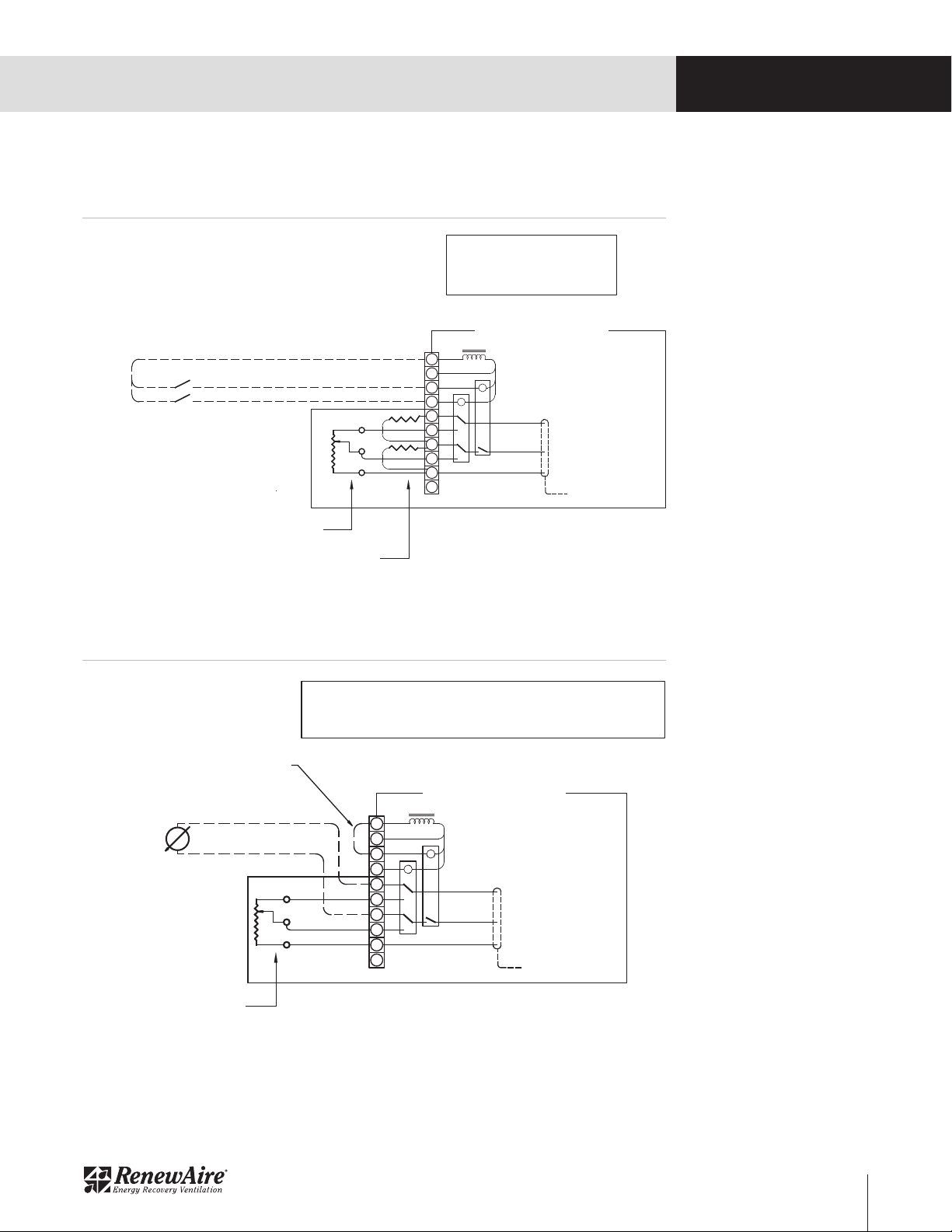
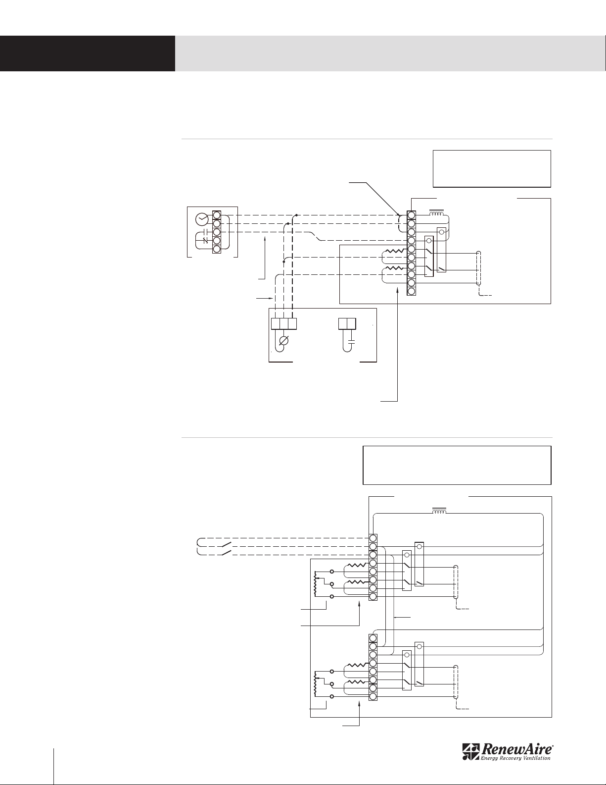
PRINCIPLES OF EXTERNAL CONTROL
The light commercial units with ECM motors are
designed for control by a wide variety of low voltage
(24VAC) controls to meet the ventilation needs of the
facility. These include time clock, occupancy sensor,
carbon dioxide sensor, building management system
(BMS) and others. These devices are commonly
known as 2-wire, 3-wire, and 4-wire devices. Re-
newAire offers separately the following for standalone
control of the ERV:
• Digital Time Clocks TC7D-W and TC7D-E
• Occupancy Sensors MC-C and MC-W
• Carbon Dioxide Sensor/Controllers CO2-W
and CO2-D
HE1X & HE1.5X ONLY
The external control device connects to the Light
Commercial unit to operate each blower independent-
ly or for one blower to act as leader and the other
blower to act as follower. When operating inde-
pendently, a single external switch or relay calls for
operation but each speed control motor can respond
independently to switch or analog signal source.
When acting as leader-follower, again, a single
external source calls for operation and then one motor
responds to the input signal. The Light Commercial
HE1X & HE1.5X units have the versatility that either
the exhaust air (EA) motor or the fresh air (FA) motor
can act as leader. Connection of an external control
device to the Light Commercial Unit is simple. All
external control device wires connect to a terminal
block(s) in the unit’s electrical box.

ECM MOTORS
9
1.800.627.4499 ECM ECM MOTOR SUPPLEMENTAL MANUAL RENEWAIRE.COM
WIRING SCHEMATICS BY
CONTROL METHOD
INSTALLATION
1
2
3
4
5
Call for UNIT Operation.
C
On-board 24VAC Power
EV450-ECM
MANUAL OFF/ON SWITCH.
SPEED 1 SET BY RESISTORS.
MANUAL SWITCH ACTIVATES SPEED 2.
10K POTENTIOMETER SETS SPEED 2.
6
7
8
9
10
Master ON/OFF Relay
Analog Signal REFERENCE
Analog Signal IN
C
Analog Signal GROUND
HIGH/LOW Relay
To Motor Controller
Factory-installed Resisters between
terminals 5, 7 & 9 set SPEED 1
Factory-installed 10K Potentiomenter at
terminals 6, 8 & 9 sets SPEED 2
(2)FIELD-INSTALLED SPST SWITCHES FACTORY WIRING
Call for HIGH SPEED.
FIG 2
EV450-ECM: FIXED SPEED CONTROL
3/4" = 1" -- Do not scale drawing
RenewAire LLC
1
2
3
4
5
On-board 24VAC Power
6
7
8
9
10
Master ON/OFF Relay
CHIGH/LOW Relay
FIG 3
EV450-ECM
JUMPER FOR CONSTANT READINESS TO RUN.
SPEED 1 SET BY 0-10vdc INPUT FROM BUILDING MANAGEMENT SYSTEM (BMS).
SPEED 2 UNUSED.
Analog Signal IN
To Motor Controller
Analog Signal REFERENCE
Analog Signal GROUND
BMS 0-10vdc
REMOVE FACTORY-INSTALLED RESISTORS
FROM TERMINALS 5, 7 & 9.
C
FIELD-INSTALLED JUMPER
FACTORY WIRING
Factory-installed 10K Potentiometer at
terminals 6, 8 & 9sets SPEED 2
EV450-ECM: BMS SYSTEM CONNECTION
3/4" = 1" -- Do not scale drawing
RenewAire LLC
EV450 FIXED SPEED CONTROL
EV450 0-10 VDC SIGNAL FROM EXTERNAL CONTROL OR BMS

ECM MOTORS
RENEWAIRE.COM ECM MOTOR SUPPLEMENTAL MANUAL 1.800.627.4499
10
WIRING SCHEMATICS BY
CONTROL METHOD
INSTALLATION
1
2
3
4
5
On-board 24VAC Power
EV450-ECM
JUMPER FOR CONSTANT ON.
SPEED 1 SET BY RESISTORS.
TIME CLOCK ACTIVATES SPEED 2.
CO2 CONTROLLER SETS SPEED 2.
6
7
8
9
10
Master ON/OFF Relay
Analog Signal IN
CHIGH/LOW Relay
To Motor Controller
FIG 4
Factory-installed Resisters between
terminals 5, 7 & 9 determine SPEED 1
1
2
3
4
5
CO2 CONTROLLER
TIME CLOCK
FIELD-INSTALLED CO2
CONTROLLER SETS SPEED 2
FIELD-INSTALLED TIME CLOCK
ACTIVATES SPEED 2 Analog Signal REFERENCE
Analog Signal GROUND
0-10vdc
TC7D-W/E
CO2-W/D
DISCONNECT FACTORY-INSTALLED
POTENTIOMETER FROM TERMINALS 6, 8 & 9.
C
FIELD-INSTALLED JUMPER
FACTORY WIRING
CO2
COM
PWR
24VAC IN
EV450-ECM: TIME CLOCK & CO2 Controller
3/4" = 1" -- Do not scale drawing
RenewAire LLC
1
2
3
4
5
C
On-board 24VAC Power
6
7
8
Master ON/OFF Relay FAN 1
CSPEED 2 Relay FAN 1
Analog Signal IN FAN 1
To EA Motor Controller FAN 1
Analog Signal REFERENCE FAN 1
Analog Signal GROUND FAN 1
1
2
3
4
5
C
6
7
8
Master ON/OFF Relay FAN 2
CSPEED 2 Relay FAN 2
Analog Signal IN FAN 2
To FA Motor Controller FAN 2
Analog Signal REFERENCE FAN 2
Analog Signal GROUND FAN 2
"-"
"+"
Call for UNIT Operation.
Call for SPEED 2
(2) FIELD-INSTALLED SPST SWITCHES
Factory-installed jumpers passes "ON" and
"MODE" signals to Fan 2
HE1X AND HE1.5X-ECM
MANUAL OFF/ON SWITCH.
SPEED 1 SET BY RESISTORS FOR EACH BLOWER.
MANUAL SWITCH ACTIVATES SPEED 2 (BOTH BLOWERS).
SPEED 2 SET FOR EACH BLOWER BY SEPARATE 10K POTENTIOMETERS.
FIG 5
EA
FA
Factory-installed Resisters between
terminals 4, 6 & 8 set SPEED 1
Factory-installed 10K Potentiometer
terminals 5, 7 & 8 set SPEED 2
Factory-installed Resisters between
terminals 4, 6 & 8 set SPEED 1
Factory-installed 10K Potentiometer
terminals 5, 7 & 8 set SPEED 2
FACTORY WIRING
HE-1X AND HE1.5X-ECM: MANUAL OFF/ON;
FIXED LOW SPEED, HIGH SPEEDS SET BY
POTENTIOMETER
3/4" = 1" -- Do not scale drawing
RenewAire LLC
EV450 0-10 VDC SIGNAL FROM CO2 CONTROL
HE1X & HE1.5X FIXED SPEED CONTROL

ECM MOTORS
11
1.800.627.4499 ECM ECM MOTOR SUPPLEMENTAL MANUAL RENEWAIRE.COM
WIRING SCHEMATICS BY
CONTROL METHOD
INSTALLATION
FIG 6
1
2
3
4
5
On-board 24VAC Power
6
7
8
Analog Signal IN FAN 1
To EA Motor Controller FAN 1
Analog Signal REFERENCE FAN 1
Analog Signal GROUND FAN 1
1
2
3
4
5
6
7
8
Analog Signal IN FAN 2
To FA Motor Controller FAN 2
Analog Signal REFERENCE FAN 2
Analog Signal GROUND FAN 2
"-"
"+"
Factory-installed jumpers passes "ON" and
"MODE" signals to Fan 2
BMS 0-10vdc output 1: SPEED 1
HE1X and HE1.5X-ECM
JUMPER FOR CONSTANT ON.
SPEED 1 SET BY 0-10vdc OUTPUT(S) OF BUILDING MANAGEMENT SYSTEM (BMS).
SPEED 2 UNUSED.
EA
FA
4
5
6
7
8
EA
FA
4
5
6
7
8
BMS 0-10vdc output 1: SPEED 1
BMS 0-10vdc output 2: SPEED 1
SINGLE BMS OUTPUT SETS SPEED 1 FOR
BLOWER 1 (EA).
LEADER-FOLLOWER JUMPERS BETWEEN
TERMINALS EA-4 & FA-4, AND EA-6 & FA-6 SET
EQUAL SPEED 1 FOR BLOWER 2 (FA).
ALTERNATELY, TWO BMS OUTPUTS
SEPARATELY SET SPEED 1 FOR BLOWER 1
(EA) AND SPEED 1 FOR BLOWER 2 (FA).
REMOVE FACTORY-INSTALLED
RESISTORS FROM TERMINALS 4, 6 & 8.
FACTORY-INSTALLED
POTENTIOMETERS NOT SHOWN.
CMaster ON/OFF Relay FAN 1
CSPEED 2 Relay FAN 1
CMaster ON/OFF Relay FAN 2
CSPEED 2 Relay FAN 2
FACTORY WIRING
FIELD-INSTALLED JUMPER
HE-1X-ECM: MANUAL OFF/ON, BMS
3/4" = 1" -- Do not scale drawing
RenewAire LLC
1
2
3
4
5
On-board 24VAC Power
6
7
8
Analog Signal IN FAN 1
To EA Motor Controller FAN 1
Analog Signal REFERENCE FAN 1
Analog Signal GROUND FAN 1
1
2
3
4
5
6
7
8
Analog Signal IN FAN 2
To FA Motor Controller FAN 2
Analog Signal REFERENCE FAN 2
Analog Signal GROUND FAN 2
"-"
"+"
Call for SPEED 2
Factory-installed jumpers passes "ON" and
"MODE" signals to Fan 2
HE1X AND HE1.5X-ECM
JUMPER FOR CONSTANT UNIT ON.
SPEED 1 SET BY 10K POTENTIOMETER (EACH BLOWER).
TIME CLOCK ACTIVATES SPEED 2 DURING OCCUPANCY..
CO2 CONTROL SETS SPEED 2.
FIG 7
1
2
3
4
5
TIME CLOCK
FIELD-INSTALLED CO2
CONTROLLER SETS SPEED 2
FIELD-INSTALLED TIME CLOCK
ACTIVATES SPEED 2 EA
FA
MOVE POTENTIOMETER LEADS TO TERMINALS 4 & 6.
REMOVE FACTORY-INSTALLED RESISTORS.
TC7D-W/E
CMaster ON/OFF Relay FAN 1
CSPEED 2 Relay FAN 1
CMaster ON/OFF Relay FAN 2
CSPEED 2 Relay FAN 2
FACTORY WIRING
FIELD-INSTALLED JUMPER
CO2 CONTROLLER
0-10vdc
CO2-W/D
CO2
COM
PWR
24VAC IN
HE-1X-ECM: TIME CLOCK AND CO2
CONTROLLER
3/4" = 1" -- Do not scale drawing
RenewAire LLC
HE1X & HE1.5X 0-10 VDC SIGNAL FROM EXTERNAL CONTROL OR BMS
HE1X & HE1.5X 0-10 VDC SIGNAL FROM CO2 CONTROL

ECM MOTORS
RENEWAIRE.COM ECM MOTOR SUPPLEMENTAL MANUAL 1.800.627.4499
12
WIRING SCHEMATICS BY
CONTROL METHOD
INSTALLATION
1
2
3
4
5
C
On-board 24VAC Power
6
7
8
Master ON/OFF Relay FAN 1
CSPEED 2 Relay FAN 1
Analog Signal IN FAN 1
To EA Motor Controller FAN 1
Analog Signal REFERENCE FAN 1
Analog Signal GROUND FAN 1
1
2
3
4
5
C
6
7
8
Master ON/OFF Relay FAN 2
CSPEED 2 Relay FAN 2
Analog Signal IN FAN 2
To FA Motor Controller FAN 2
Analog Signal REFERENCE FAN 2
Analog Signal GROUND FAN 2
"-"
"+"
Call for UNIT Operation.
Call for SPEED 2
(2) FIELD-INSTALLED SPST SWITCHES
Factory-installed jumpers passes "ON" and
"MODE" signals to Fan 2
SC-ECM
MANUAL OFF/ON SWITCH.
SPEED 1 SET BY RESISTORS FOR EACH BLOWER.
MANUAL SWITCH ACTIVATES SPEED 2 (BOTH BLOWERS).
SPEED 2 SET FOR EACH BLOWER BY SEPARATE 10K POTENTIOMETERS.
FIG 8
EA
FA
Factory-installed Resisters between
terminals 4, 6 & 8 set SPEED 1
Field installed SC-ECM Accessory
terminals 5, 7 & 8 set SPEED 2
Factory-installed Resisters between
terminals 4, 6 & 8 set SPEED 1
Field installed SC-ECM Accessory
terminals 5, 7 & 8 set SPEED 2
FACTORY WIRING
SC-ECM: MANUAL OFF/ON;
FIXED LOW SPEED, HIGH SPEEDS SET BY
POTENTIOMETER
3/4" = 1" -- Do not scale drawing
RenewAire LLC
1
2
3
4
5
C
On-board 24VAC Power
6
7
8
Master ON/OFF Relay FAN 1
CSPEED 2 Relay FAN 1
Analog Signal IN FAN 1
To EA Motor Controller FAN 1
Analog Signal REFERENCE FAN 1
Analog Signal GROUND FAN 1
1
2
3
4
5
C
6
7
8
Master ON/OFF Relay FAN 2
CSPEED 2 Relay FAN 2
Analog Signal IN FAN 2
To FA Motor Controller FAN 2
Analog Signal REFERENCE FAN 2
Analog Signal GROUND FAN 2
"-"
"+"
Call for UNIT Operation.
Call for SPEED 2
(2) FIELD-INSTALLED SPST SWITCHES
Factory-installed jumpers passes "ON" and
"MODE" signals to Fan 2
SC-ECM
MANUAL OFF/ON SWITCH.
SPEED 1 SET BY RESISTORS FOR EACH BLOWER.
MANUAL SWITCH ACTIVATES SPEED 2 (BOTH BLOWERS).
SPEED 2 SET FOR EACH BLOWER BY SEPARATE 10K POTENTIOMETERS.
FIG 8
EA
FA
Factory-installed Resisters between
terminals 4, 6 & 8 set SPEED 1
Field installed SC-ECM Accessory
terminals 5, 7 & 8 set SPEED 2
Factory-installed Resisters between
terminals 4, 6 & 8 set SPEED 1
Field installed SC-ECM Accessory
terminals 5, 7 & 8 set SPEED 2
FACTORY WIRING
SC-ECM: MANUAL OFF/ON;
FIXED LOW SPEED, HIGH SPEEDS SET BY
POTENTIOMETER
3/4" = 1" -- Do not scale drawing
RenewAire LLC
SPEED CONTROL SC-ECM ACCESSORY CONTROL

ECM MOTORS
13
1.800.627.4499 ECM ECM MOTOR SUPPLEMENTAL MANUAL RENEWAIRE.COM
AIRFLOW PERFORMANCE
The ERV is factory wired to operate at low fixed
speed and high variable speed.
Airflows must be measured and the unit’s potenti-
ometers adjusted so that it operates at the airflow
volumes specified for the installation.
Use the pressure taps in the core and filter doors
to determine the airflow. Figure 1 translates the
pressure drop across the energy recovery core to
the actual airflow volume.
Very low airflow rates may result in fouling of the
energy exchanger core. Do not reduce airflow to below
250 cfm per core.
CAUTION
Make sure clean filters are installed before balancing airflow.
Dirty or clogged filters reduce airflow through the unit.
CAUTION
MEASURING AIRFLOW
Equipment Required
• Magnehelic gauge or other device capable of
measuring 0-1.5 in. water of differential pressure.
• 2 pieces of flexible tubing, 1/8” ID, 1/16” wall
works best.
NOTE: Be sure to remove cap from pressure port
before inserting tubing. Insure tubing is well seated
in pressure ports.
NOTE: The tubing should extend in the pressure
port approximately 1 inch.
Cross Core Static Pressure Measurement
Instructions
• The individual differential static pressures (DP)
are measured using the installed pressure ports
located in the front of the units core access doors.
NOTE: These ports are carefully located on the unit
to give the most accurate airflow measurement.
NOTE: Do not relocate pressure ports.
• To read SCFM of Fresh Air (FA) install the “high”
pressure side (+) of your measuring device to the
Outside Air (OA) port and the “low” pressure side
(-) to the Fresh Air (FA) port.
• To read SCFM of Room Air (RA) install the “high”
pressure side (+) of your measuring device to the
Room Air (RA) port and the “low” pressure side
(-) to the Exhaust Air (EA) port.
• Use the reading displayed on your measurement
device to cross reference the CFM output using
the conversion chart.
NOTE: Be sure to replace cap into pressure port
when air flow measuring is completed.
• Adjust air flow by changing the potentiometer
setting for the measured airstream.
NOTE: For best performance the airflow rate for
both the Fresh Air and the Exhaust Air should be
roughly equal (“balanced”). In some facilities a
slight positive or negative pressure in the building
is desired. RenewAire energy recovery ventilators
can generally operate with a flow imbalance of up
to 20% without significant loss in energy recovery
efficiency.
AIRFLOW
START-UP

ECM MOTORS
RENEWAIRE.COM ECM MOTOR SUPPLEMENTAL MANUAL 1.800.627.4499
14
AIRFLOW VS. PRESSURE DROPS
START-UP
AIRFLOW PREDICTED BY PRESSURE DROP ACROSS CORE (SCFM))
DP
(“H2O)
EV450IN ECM HE1XINV ECM HE1XINH ECM HE1.5XIN ECM HE1XRT ECM HE1XRTC ECM HE1.5XRT ECM
FA RA FA RA FA RA FA RA FA RA FA RA FA RA
0.10 -- -- -- -- -- -- -- -- -- -- -- -- 335 --
0.15 -- -- -- -- -- -- 380 320 -- -- -- -- 450 --
0.20 200 200 280 -- 260 -- 500 440 -- -- -- -- 555 --
0.25 225 225 330 270 310 290 620 565 -- -- -- -- 650 --
0.30 245 245 380 320 360 340 740 695 280 250 -- -- 745 --
0.35 265 265 425 375 415 390 860 825 325 290 -- -- 835 300
0.40 285 285 470 430 470 440 980 960 370 330 -- -- 920 380
0.45 305 305 520 480 520 490 1095 1095 415 370 -- -- 1005 475
0.50 330 330 570 530 570 540 1215 1235 460 410 650 -- 1085 575
0.55 350 350 620 580 620 590 1330 1375 515 455 688 -- 1165 685
0.60 370 370 670 630 670 640 1450 1515 550 500 725 555 1240 805
0.65 390 390 720 680 720 690 1565 -- 595 540 770 610 1315 935
0.70 410 410 770 730 770 740 -- -- 640 580 815 665 1385 1070
0.75 430 430 815 785 820 790 -- -- 690 620 853 720 1460 12220
0.80 455 455 860 840 870 840 -- -- 740 660 890 775 1530 1375
0.85 475 475 910 890 920 890 -- -- 785 700 933 828 -- 1535
0.90 495 495 960 940 970 940 -- -- 830 740 975 880 -- --
0.95 -- -- 1010 990 1020 990 -- -- 875 785 1018 938 -- --
1.00 -- -- 1060 1040 1070 1040 -- -- 920 830 1060 995 -- --
1.05 -- -- -- 1090 -- 1090 -- -- 965 870 -- 1048 -- --
1.10 -- -- -- -- -- -- -- -- 1010 910 -- 1100 -- --

ECM MOTORS
15
1.800.627.4499 ECM ECM MOTOR SUPPLEMENTAL MANUAL RENEWAIRE.COM
NOTES

UNMATCHED VENTILATION SUPPORT
As much as our unsurpassed quality and performance, our customers can also depend on our
professional support staff for swift, professional assistance with all their technical, application,
and service needs. Every time. Anywhere.
At RenewAire — unlike other ventilation suppliers — advanced ventilation solutions are all
we do. Our sole passion. Which is why for all commercial projects, we are the “V” in HVAC...
and the only name you need to know.
USA
(800) 627-4499
FAX: (608) 221-2824
4510 HELGESEN DRIVE
MADISON, WISCONSIN 53718 USA
WWW.RENEWAIRE.COM
CANADA
(905) 475-8989
FAX: (905) 475-5231
WWW.MITSUBISHIELECTRIC.CA
MEXICO,
CENTRAL & SOUTH AMERICA
52 (222) 2 233 911
FAX: 52 (222) 2 233 914
WWW.SOLER-PALAU.MX 138297_004 (9/16)
Other manuals for EV450IN
1
This manual suits for next models
5
Table of contents