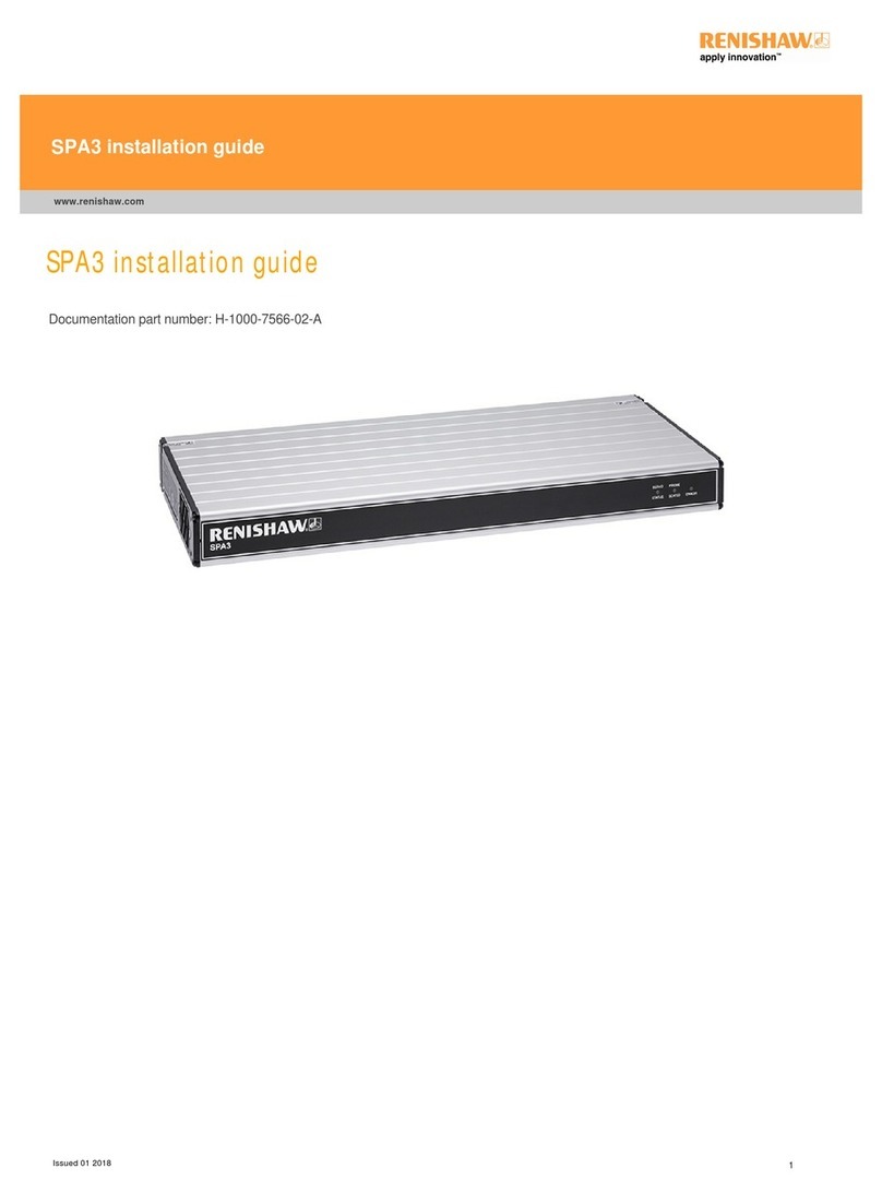
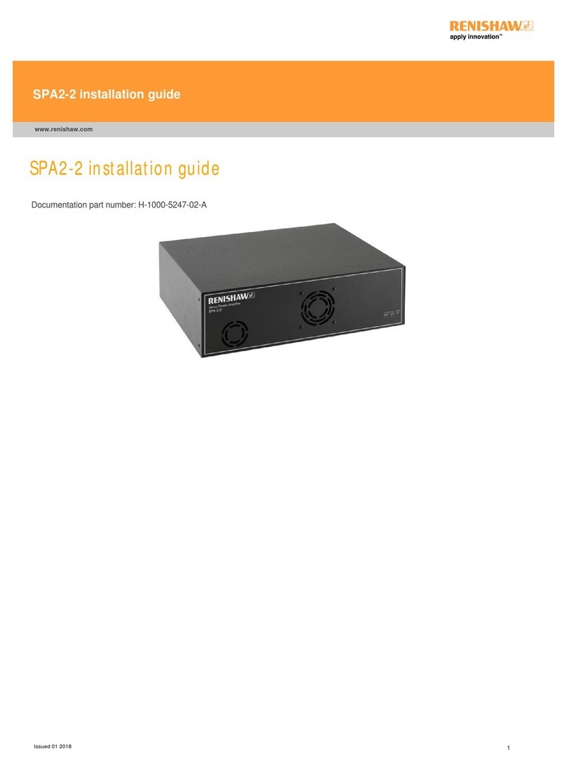
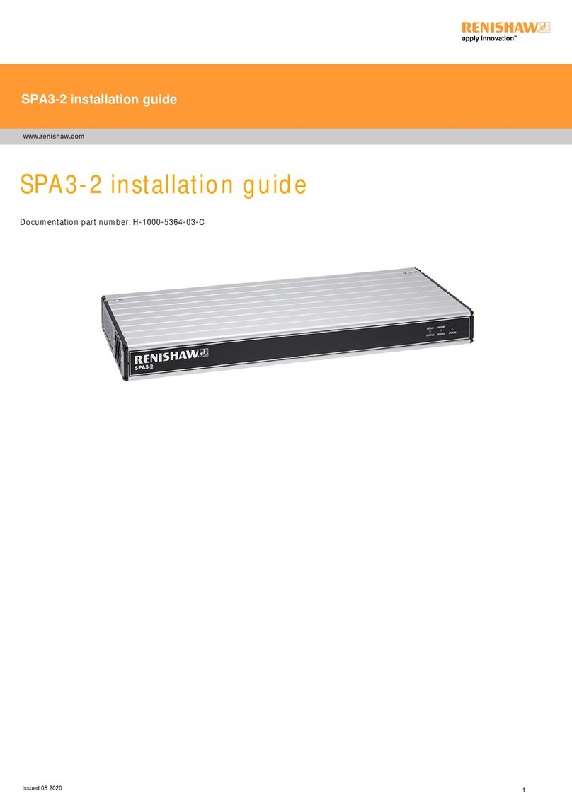
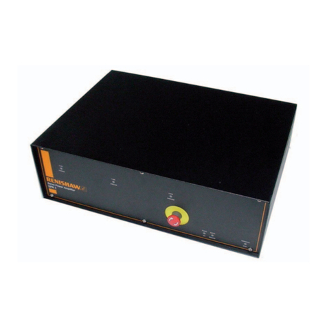
Renishaw H-1000-5068-02-A SPA1 s User manual

Installation guide
H-1000-5068-02-A
SPA1 servo power amplifier

© 2002 Renishaw. All rights reserved.
Renishaw® is a registered trademark of Renishaw plc.
This document may not be copied or reproduced in
whole or in part, or transferred to any other media or
language, by any means, without the prior written
permission of Renishaw.
The publication of material within this document does
not imply freedom from the patent rights of Renishaw
plc.
Disclaimer
Considerable effort has been made to ensure that the
contents of this document are free from inaccuracies
and omissions. However, Renishaw makes no
warranties with respect to the contents of this
document and specifically disclaims any implied
warranties. Renishaw reserves the right to make
changes to this document and to the product
described herein without obligation to notify any
person of such changes.
Trademarks
All brand names and product names used in this
document are trade names, service marks,
trademarks, or registered trademarks of their
respective owners.
Care of equipment
Renishaw probes and associated systems are
precision tools used for obtaining precise
measurements and must therefore be treated with
care.
Changes to Renishaw products
Renishaw reserves the right to improve, change or
modify its hardware or software without incurring any
obligations to make changes to Renishaw equipment
previously sold.
Renishaw part no: H-1000-5068-02-A
Issued: September 2002
Warranty
Renishaw plc warrants its equipment for a limited
period (as set out in our Standard Terms and
Conditions of Sale) provided that it is installed exactly
as defined in associated Renishaw documentation.
Prior consent must be obtained from Renishaw if non-
Renishaw equipment (e.g. interfaces and/or cabling) is
to be used or substituted. Failure to comply with this
will invalidate the Renishaw warranty.
Claims under warranty must be made from authorised
Service Centres only, which may be advised by the
supplier or distributor.
References and associated documents
It is recommended that the following documentation is
referenced to when installing the SPA1.
Renishaw documents
Documentation supplied on Renishaw UCC1 software
CD.
Document No. Title
H-1000-5056 UCC-1 controller, installation
manual
H-1000-5057 UCC-1 controller, programmer’s
guide
H-1000-5058 RENICIS user’s guide
H-1000-5227 Servo tuning guide
H-1000-5067 MCU installation and user’s guide
External documents
National and international standards including the
following may be applicable to the finished machine or
installation:
EN 292-2:1991 (Safety of machinery - Basic concepts,
general principles for design - Part 2: Technical
principles and specifications.
EN (IEC) 60204-1:1997 (Safety of machinery -
Electrical equipment of machines - Part 1: General
requirements).”
Document No. Title
0470-0005 User guide, Mini Maestro drive

Warnings 1
GB
WARNINGS
The machine manufacturer or the installer of this
equipment is responsible for ensuring that the finished
machine complies with the necessary safety regulations
and standards including those referenced in this
handbook.
Theuseriscautionedthatpowermaybeavailableto
the servo drives when the machine is stopped. To
ensure that no unexpected movement can occur, the
user should activate the Emergency Stop system to
remove power before entering the danger zone.
Beware of unexpected movement. The user should
remain outside of the full working envelope of probe
head / extension / probe combinations.
In all applications involving the use of Machine tools or
CMMs, eye protection is recommended.
Disconnect mains before removing covers. Return
defective units to an authorised Renishaw customer
service centre
For instructions regarding safe cleaning of Renishaw
product, refer to MAINTENANCE section of the relevant
product documentation.
Refer to the machine supplier’s operating instructions
It is the machine supplier’s responsibility to ensure that
the user is made aware of any hazards involved in
operation, including those mentioned in Renishaw
product documentation, and to ensure adequate guards
and safety interlocks are provided.
Under certain circumstances the probe outputs may
falsely indicate the status of the probe. Do not rely on
probe signals to stop machine movement.
This equipment is not suitable for use in a potentially
explosive atmosphere.
F
AVERTISEMENTS
Le fabricant de la machine ou l'installateur de cet
équipement est responsable de l'assurance que le
produit fini respecte les normes d'installation et de
sécurité y compris celles en référence dans ce manuel.
L'utilisateur doit être informé que les amplificateurs de
servo commande peuvent rester alimenté lorsque ma
machine est à l'arrêt. Pour être certain qu'aucun
mouvement intempestif ne pourra se produire, il est
impératif d'activer le bouton d'arrêt d'urgence pour
couper la puissance avant de pénétrer en zone
dangereuse.
Attention aux mouvements brusques. L'utilisateur doit
toujours rester en dehors de la zone de sécurité des
installations multiples Tête de
Palpeur/Rallonge/Palpeur.
Le port de lunettes de protection est recommandé pour
toute application sur machine-outil et MMC.
Couper l'alimentation secteur avant de retirer les
couvercles. Renvoyer toute machine défectueuse à un
Centre Après Vente Renishaw agréé.
Les conseils de nettoyage en toute sécurité des
produits Renishaw figurent dans la section
MAINTENANCE de votre documentation.
Consulter le mode d’emploi du fournisseur de la
machine.
Il incombe au fournisseur de la machine d’assurer que
l’utilisateur prenne connaissance des dangers
d'exploitation, y compris ceux décrits dans la
documentation du produit Renishaw, et d'assurer que
des protections et verrouillages de sûreté adéquats
soient prévus.
Dans certains cas, il est possible que le signal du
palpeur indique à tort l'état que le palpeur est au repos.
Ne pas se fier aux signaux du palpeur qui ne
garantissent pas toujours l’arrêt de la machine.
Cet équipement est impropre à son utilisation en
atmosphère explosive.

2Warnings
D
ACHTUNG
Der Hersteller der Maschine oder derjenige, der dieses
Produkt auf der Maschine installiert ist dafür
verantwortlich, dass die fertiggestellte Maschine den
notwendigen Sicherheitsbestimmungen und Standards,
einschließlich derer in diesem Handbuch erwähnten,
entspricht.
Der Anwender sei gewarnt, dass auch bei gestoppter
Maschine an den Servoantrieben Spannung anliegen
kann. Um sicherzustellen, dass keine unerwarteten
Verfahrbewegungen auftreten können, sollte der
Anwender vor notwendigen Arbeiten in den
Gefahrenzonen das Notstop-System aktivieren, um die
Stromversorgung zu unterbrechen.
Auf unerwartete Bewegungen achten. Der Anwender
sol sich immer außerhalb des Meßtasterkopf-Arm-
Meßtaster-Bereichs aufhalten.
Bei der Bedienung von Werkzeugmaschinen oder
Koordinatenmeßanlagen ist Augenschutz empfohlen.
Vor dem Abnehmen von Abdeckungen vom Netz
trennen. Im Falle von Mängeln sind diese Geräte an
Ihren Renishaw Kundendienst zu senden.
Anleitungen über die sichere Reinigung von
Renishaw-Produkten sind in Kapitel WARTUNG
(MAINTENANCE) in der Produktdokumentation
enthalten.
Beziehen Sie sich auf die Wartungsanleitungen des
Lieferanten.
Es obliegt dem Maschinenlieferanten, den Anwender
über alle Gefahren, die sich aus dem der Ausrüstung,
einschließlich der, die in der Renishaw
Produktdokumentation erwähnt sind, zu unterrichten
und zu versichern, daß ausreichende
Sicherheitsvorrichtungen und Verriegelungen eingebaut
sind.
Unter gewissen Umständen könnte das Meßtastersignal
falscherweise melden, daß der Meßtaster nicht
ausgelenkt ist. Verlassen Sie sich nicht allein auf
Sondensignale, um sich über Maschinenbewegungen
zu informieren.
Der Verstärker darf nicht in explosiver Atmosphäre
verwendet werden.
I
AVVERTENZE
Il costruttore della macchina o l'installatore di questa
apparecchiatura è responsabile di assicurarsi che la
macchina, una volta completata, sia conforme alle
norme e agli standard di sicurezza necessari, inclusi
quelli indicati in questo manuale.
L'utilizzatore è avvisato della possibilità che la
macchina, anche se stazionaria, sia alimentata e in
potenza. Per assicurarsi che non si verifichino
movimenti inaspettati, l'utilizzatore deve attivare il
sistema di arresto di emergenza per togliere potenza
alla macchina prima di entrare nell'area di lavoro.
Fare attenzione ai movimenti inaspettati. Si
raccomanda all'utente di tenersi al di fuori dell’involucro
operativo della testina della sonda, prolunghe e altre
varianti della sonda.
Si raccomanda di indossare occhiali di protezione in
applicazioni che comportano macchine utensili e
macchine per misurare a coordinate.
Staccare dalla rete prima di togliere dalle coperture. In
caso di guasto, rendere l'apparecchio a uno dei Centri
di Assistenza Renishaw.
Per le istruzioni relative alla pulizia dei prodotti
Renishaw, fare riferimento alla sezione
MANUTENZIONE (MAINTENANCE) della
documentazione del prodotto.
Consultare le istruzioni d’uso del fabbricante della
macchina.
Il fornitore della macchina ha la responsabilità di
avvertire l'utente dei pericoli inerenti al funzionamento
della stessa, compresi quelli riportati nelle istruzioni
della Renishaw, e di mettere a disposizione i ripari di
sicurezza e gli interruttori di esclusione.
E' possibile, in certe situazioni, che la sonda emetta
erroneamente un segnale che la sonda è in posizione.
Evitare di fare affidamento sugli impulsi trasmessi dalla
sonda per arrestare la macchina.
Questo dispositivo non è adatto all'uso in ambienti
potenzialmente esplosivi.
Warnings 3
E
ADVERTANCIAS
El fabricante de la máquina o el instalador de este
equipo es responsable de asegurarse de que la
máquina acabada cumple con las regulaciones de
seguridad necesarias y con las normas, incluyendo
aquéllas referenciadas en este manual.
El usuario es avisado de que puede haber tensión en
los servo accionamientos cuando la máquina está
parada. Para asegurarse de que no ocurre un
movimiento inesperado, el usuario debería activar el
sistemadeParodeEmergenciaparaquitarlatensión
antes de entrar en la zona de peligro.
Tener cuidado con los movimientos inesperados. El
usuario debe quedarse fuera del grupo operativo
completo compuesto por la cabeza de
sonda/extensión/sonda o cualquier combinación de las
mismas.
Se recomienda usar protección para los ojos en todas
las aplicaciones que implican el uso de máquinas
herramientas y máquinas de medición de coordenadas.
Desconectar la aimentación antes de retirar las tapas.
Las unidades defectuosas deben ser devueltas a un
Centro de Servicio al Cliente Renishaw.
Para instrucciones sobre seguridad a la hora de limpiar
los productos Renishaw, remitirse a la sección titulada
MANTENIMIENTO (MAINTENANCE) en la
documentación sobre el producto.
Remitirse a las instrucciones de manejo del proveedor
de la máquina.
Corresponde al proveedor de la máquina asegurar que
el usuario esté consciente de cualquier peligro que
implica el manejo de la máquina, incluyendo los que se
mencionan en la documentación sobre los productos
Renishaw y le corresponde también asegurarse de
proporcionar dispositivos de protección y dispositivos
de bloqueo de seguridad adecuados.
Bajo determinadas circunstancias la señal de la sonda
puede indicar erroneamente que la sonda está
asentada. No fiarse de las señales de la sonda para
parar el movimiento de la máquina.
Este equipo no es adecuado para ser utilizado en una
atmósfera pontencialmente explosiva.
P
AVISOS
O fabricante da máquina ou o instalador deste
equipamento é responsável em assegurar que quando
terminada, a máquina esteja em acordo com os
padrões e regulamentos de segurança, incluindo os
mencionados neste manual.
O usuário deve ser avisado que os motores podem
estar energizados quando a máquina estiver parada.
Para assegurar que nenhum movimento ocorra, o
usuário deve ativar o sistema de parada de
emergência, para desligar a energia, antes de entrar
em algum local perigoso.
Tomar cuidado com movimento inesperado. O utilizador
deve permanecer fora do perímetro da área de trabalho
das combinações Cabeça da Sonda/Extensão/ Sonda.
Em todas as aplicações que envolvam a utilização de
Máquinas-Ferramenta e CMMs, recomenda-se usar
protecção para os olhos.
Desligar o sector antes de retirar as tampas. Devolver
unidades avariadas a um Centro de Atendimento a
Clientes Renishaw.
Para instruções relativas à limpeza segura de produtos
Renishaw, consultar a secção MANUTENÇÃO
(MAINTENANCE) da documentação do produto.
Consultar as instruções de funcionamento do
fornecedor da máquina.
É responsabilidade do fornecedor da máquina
assegurar que o utilizador é consciencializado de
quaisquer perigos envolvidos na operação, incluindo os
mencionados na documentação do produto Renishaw e
assegurar que são fornecidos resguardos e
interbloqueios de segurança adequados.
Em certas circunstâncias, o sinal da sonda pode indicar
falsamente uma condição de sonda assentada. Não
confiar em sinais da sonda para parar o movimento da
máquina.
Este equipamento não é adequado para ser usado em
locais com potencial explosivo.

4Warnings
DK
ADVARSLER
Det er maskinproducentens eller installatøren af dette
udstyrs ansvar at sikre, at den færdige maskine
overholder alle relevante sikkerhedsregulativer og
standarder, indbefattet dem, der henvises til i denne
håndbog.
Brugeren gøres opmærksom på, at der kan være
strømforsyning til servodrevene, når maskinen er
standset. For at sikre mod uventet bevægelse bør
brugeren aktivere nødstopsystemet, der afbryder
strømforsyningen, før indgang i farezonen.
Pas på uventede bevægelser. Brugeren bør holde sig
uden for hele sondehovedets/forlængerens/sondens
arbejdsområde.
I alle tilfælde, hvor der anvendes værktøjs- og
koordinatmålemaskiner, anbefales det at bære
øjenbeskyttelse.
Afbryd ved lysnettet, før dækslerne demonteres. Send
alle defekte enheder til Renishaws kundeservicecenter.
Se afsnittet VEDLIGEHOLDELSE (MAINTENANCE) i
produktdokumentationen for at få instruktioner til sikker
rengøring af Renishaw-produkter.
Se maskinleverandørens brugervejledning.
Det er maskinleverandørens ansvar at sikre, at
brugeren er bekendt med eventuelle risici i forbindelse
med driften, herunder de risici, som er nævnt i
Renishaws produktdokumentation, og at sikre, at der er
tilstrækkelig afskærmning og sikkerhedsblokeringer.
Under visse omstændigheder kan sondesignalet ved en
fejl angive, at sonden står stille. Stol ikke på, at
sondesignaler stopper maskinens bevægelse.
Dette udstyr er uegnet til brug i en atmosfære med
eksplosionsfare.
NL
WAARSUCHSWINGEN
De machinefabrikant of de installateur van deze
apparatuur moet garanderen dat de afgewerkte
machine voldoet aan de vereiste
veiligheidsvoorschriften en –normen, met inbegrip van
deze waarnaar verwezen wordt in dit handboek.
De gebruiker is ervan verwittigd dat drijfkracht naar de
servomechanismen aanwezig kan zijn zelfs als de
machine stilgelegd wordt. Om onverwachte bewegingen
te vermijden, moet de gebruiker het Noodstopsysteem
activeren om de drijfkracht uit te schakelen vooraleer
zich in de gevarenzone te begeven.
Oppassen voor onverwachte beweging. De gebruiker
dient buiten het werkende signaalveld van de
Sondekop/Extensie/Sonde combinaties te blijven.
Het dragen van oogbescherming wordt tijdens gebruik
van Machinewerktuigen en CMM’s aanbevolen.
Netstroom afkoppelen alvorens de beschmerkappen af
te nemen. U kunt defecte units naar een erkend
Renishaw Klantenservice Centrum brengen of
toezenden.
Voor het veilig reinigen van Renishaw produkten wordt
verwezen naar het hoofdstuk ONDERHOUD
(MAINTENANCE) in de produktendocumentatie.
De bedieningsinstructies van de machineleverancier
raadplegen.
De leverancier van de machine is ervoor
verantwoordelijk dat de gebruiker op de hoogte wordt
gesteld van de risico’s die verbonden zijn aan
bediening, waaronder de risico’s die vermeld worden in
de produktendocumentatie van Renishaw. De
leverancier dient er tevens voor te zorgen dat de
gebruiker is voorzien van voldoende beveiligingen en
veiligheidsgrendelinrichtingen.
Onder bepaalde omstandigheden kan het sondesignaal
een onjuiste sondetoestand aangeven. Vertrouw niet op
de sondesignalen voor het stoppen van de
machinebeweging.
Deze apparatuur is niet geschikt voor gebruik in een
potentieel explosieve omgeving.

Warnings 5
SW
VARNING
Antingen maskintillverkaren eller den som installerar
denna utrustning ansvarar för att säkerställa att den
färdiga maskinen uppfyller tillämpliga säkerhetskrav och
–standarder, inklusive dem som nämns i denna
handbok.
Användaren måste vara medveten om att ström kan
föreligga vid servodrivningarna när maskinen är
stoppad. För att eliminera risken för oväntade rörelser
ska användaren aktivera nödstoppsystemet, för att
koppla bort strömmen, innan arbeten utförs inom
riskzonen.
Se upp för plötsliga rörelser. Användaren bör befinna
sig utanför arbetsområdet för sondhuvudet/
förlängningen/sond-kombinationerna.
Ögonskydd rekommenderas för alla tillämpningar som
involverar bruket av maskinverktyg och CMM.
Koppla bort näströmmen innan några kåpor tas bort.
Returnera defekta delar till ett auktoriserat Renishaw
kundcentra.
För instruktioner angående säker rengöring av
Renishaws produkter, se avsnittet UNDERHÅLL
(MAINTENANCE) i produktdokumentationen.
Se maskintillverkarens bruksanvisning.
Maskinleverantören ansvarar för att användaren
informeras om de risker som drift innebär, inklusive de
som nämns i Renishaws produktdokumentation, samt
att tillräckligt goda skydd och säkerhetsförreglingar
tillhandahålls.
Under vissa omständigheter kan sondens signal falskt
ange att en sond är monterad. Lita ej på sondsignaler
för att stoppa maskinens rörelse.
Denna utrustning ska inte användas i miljöer där
explosionsrisk föreligger.
FIN
VAROITUKSIA
Koneen valmistaja tai laitteiden asentaja on vastuussa
siitä, että valmis kone vastaa kaikkia asiaankuuluvia
turvallisuusmääräyksiä ja -säädöksiä mukaan lukien ne,
joihin tässä käyttöoppaassa viitataan.
Koneen käyttäjän tulee huomioida, että virta saattaa olla
kytketty servokoneistoon, vaikka kone onkin pysähtynyt.
Jottei koneisto liikkuisi vahingossa, virta täytyy kytkeä
irti hätäpysäytysjärjestelmällä ennen kuin vaara-aluetta
lähestytään.
Varo äkillistä liikettä. Käyttäjän tulee pysytellä täysin
anturin pään/jatkeen/anturin yhdistelmiä suojaavan
toimivan kotelon ulkopuolella.
Kaikkia työstökoneita ja koordinoituja mittauskoneita
(CMM) käytettäessä suositamme silmäsuojuksia.
Kytke itri virtaverkosta ennen suojusten poistamista.
Vialliset osat tulee palauttaa valtuutetulle Renishaw-
asiakaspalvelukeskukselle.
Renishaw-tuotteiden turvalliset puhdistusohjeet löytyvät
tuoteselosteen HUOLTOA (MAINTENANCE)
koskevasta osasta.
Katso koneen toimittajalle tarkoitettuja käyttöhjeita.
Koneen toimittaja on velvollinen selittämään käyttäjälle
mahdolliset käyttöön liittyvät vaarat, mukaan lukien
Renishaw’n tuoteselosteessa mainitut vaarat.
Toimittajan tulee myös varmistaa, että toimitus sisältää
riittävän määrän suojia ja lukkoja.
Tietyissä olosuhteissa anturimerkki saattaa osoittaa
virheellisesti, että kyseessä on anturiin liittyvä ongelma.
Älä luota anturimerkkeihin koneen liikkeen
pysäyttämiseksi.
Näitä laitteita ei saa käyttää räjähdysalttiissa tilassa.

6Warnings
GR
—–œ≈…ƒœ—œ…«”≈…”
Ο κατασκευαστής της µηχανής ή ο υπεύθυνος
εγκατάστασης του εξοπλισµού έχει την ευθύνη να
επιβεβαιώσει ότι αφού ολοκληρωθεί η µηχανή,πληροί
τα απαραίτητα στάνταρτ και απαιτήσεις ασφαλείας,
περιλαµβανοµένων και αυτών που αναφέρονται στο
παρόν εγχειρίδιο.
Ο χρήστης πρέπει να λάβει υπόψη του ότι µπορεί να
υπάρχει ρεύµαστοσερβοµηχανισµόότανηµηχανή
είναι σταµατηµένη.Για να είναι σίγουρο ότι δεν θα
συµβεί κάποια απροσδόκητη κίνηση,ο χρήστης πρέπει
να ενεργοποιήσει το σύστηµαΣταµατήµατος Έκτακτης
Ανάγκης για να διακοπή η παροχή ρεύµατος πριν
εισέλθει στην επικίνδυνη ζώνη.
—ÒÔÛÔ˜Þ- Íß̉õÌÔÚ ·ðÒÔÛ‰¸ÍÁÙùÌ ÍÈÌÞÛÂùÌ. œÈ
˜ÒÞÛÙÂÚ ðÒ›ðÂÈ Ì· ð·Ò·Ï›ÌÔõÌ ÂÍÙ¸Ú ÙÔõ˜þÒÔõðÔõ
ÂðÁÒ‹ÊÂÙ·È ·ð¸ ¸ÎÔõÚ ÙÔõÚ Ûõ̉õ·ÛÏÔýÚ
ÎÂÈÙÔõÒ„ß·Ú ÙÁÚ Íˆ·ÎÞÚ ÙÔõ·ÌȘÌÂõÙÞ, ÙÁÚ
ðÒÔ›ÍÙ·ÛÁÚ Í·È ÙÔõ·ÌȘÌÂõÙÞ.
” ¸ÎÂÚ ÙÈÚ Âˆ·ÒÏÔ„›Ú ðÔõÛõÌÂð‹„ÔÌÙ·È ÙÁ ˜ÒÞÛÁ
ÂÒ„·ÎÂßùÌ ÏÁ˜·ÌÁÏ‹ÙùÌ Í·È ÂÓ·ÒÙÁÏ‹ÙùÌ CMM,
ÛõÌÈÛÙ‹Ù·È Á ˜ÒÞÛÁ ÛõÛÍÂõÞÚ ðÒÔÛÙ·Ûß·Ú ÙùÌ
Ï·ÙÈþÌ.
¡ðÔÏÔÌþÛÙ ÙÁ ÛõÛÍÂõÞ ·ð¸ ÙÔ ‰ßÍÙõÔ ðÒÔÙÔý
·ˆ·ÈÒ›ÛÂÙÂ Ù· ðÒÔÛÙ·ÙÂõÙÈÍ‹ Í·ÎýÏÏ·Ù·.
≈ðÈÛÙÒ›¯Ù ÙÈÚ ÂηÙÙùÏ·ÙÈÍ›Ú ÛõÛÍÂõ›Ú ÛÂ
ÂÓÔõÛÈÔ‰ÔÙÁÏ›ÌÔ "›ÌÙÒÔ ≈ÓõðÁÒ›ÙÁÛÁÚ —ÂηÙþÌ ÙÁÚ
Renishaw.
√È· Ô‰Á„ßÂÚ ðÔõ·ˆÔÒÔýÌ ÙÔÌ ·Ûˆ·ÎÞÍ·Ë·ÒÈÛϸ ÙùÌ
ðÒÔú¸ÌÙùÌ Renishaw, ‚ΛðÂÙ ÙÔ Íˆ‹Î·ÈÔ
ÃAINTENANCE (”’Õ‘«–«”«) ÛÙÔ ‰È·ˆùÙÈÛÙÈ͸
õÎÈ͸ ÙÔõðÒÔú¸ÌÙÔÚ.
¬Î›ðÂÙ ÙÈÚ Ô‰Á„ßÂÚ ÎÂÈÙÔõÒ„ß·Ú ÙÔõðÒÔÏÁËÂõÙÞÙÔõ
ÏÁ˜·ÌÞÏ·ÙÔÚ.
¡ðÔÙÂÎÂßÂõËýÌÁ ÙÔõðÒÔÏÁËÂõÙÞÙÔõÏÁ˜·ÌÞÏ·ÙÔÚ
Ì· ÂÓ·Ûˆ·ÎßÛÂÈ ¸ÙÈ Ô ˜ÒÞÛÙÁÚ ÂßÌ·È ÂÌÞÏÂÒÔÚ Ùõ˜¸Ì
ÍÈ̉ýÌùÌ ðÔõÛõÌÂð‹„ÂÙ·È Á ÎÂÈÙÔõÒ„ß·,
ÛõÏðÂÒÈης·ÌÔÏ›ÌùÌ Í·È ¸ÛùÌ ·Ì·ˆ›ÒÔÌÙ·È ÛÙÔ
‰È·ˆùÙÈÛÙÈ͸ õÎÈ͸ ÙÔõðÒÔú¸ÌÙÔÚ ÙÁÚ Renishaw.
≈ßÌ·È ÂðßÛÁÚ ÂõËýÌÁ ÙÔõÌ· ÂÓ·Ûˆ·ÎßÛÂÈ ¸ÙÈ
õð‹Ò˜ÔõÌ Ù· ·ð·ÈÙÔýÏÂÌ· ðÒÔÛÙ·ÙÂõÙÈÍ‹ Í·ÎýÏÏ·Ù·
Í·È Ûõ̉›ÛÂÈÚ ·Ûˆ·ÎÂß·Ú.
’ð¸ ÔÒÈÛÏ›ÌÂÚ ÛõÌËÞÍÂÚ ÏðÔÒÂßÙÔ ÛÞÏ· ·ÌȘÌÂõÙÞ
Ì· ‰þÛÂÈ ÂÛˆ·ÎÏ›ÌÁ ›Ì‰ÂÈÓÁ Ë›ÛÁÚ ÙÔõ·ÌȘÌÂõÙÞ. ÃÁ
‚·ÛßÊÂÛÙ ÛÙ· ÛÞÏ·Ù· ·ÌȘÌÂõÙÞ„È· Ë›ÛÁ ÙÁÚ
ÍßÌÁÛÁÚ ÙÔõÏÁ˜·ÌÞÏ·ÙÔÚ ÂÍÙ¸Ú ÎÂÈÙÔõÒ„ß·Ú.
Προσοχή –Η συσκευή αυτή δεν πρέπει να
χρησιµοποιείται σε περιβάλλον µε δυνητικά εκρηκτική
ατµόσφαιρα.

FCC statement 7
FCC
Information to user (FCC section 15.105)
This equipment has been tested and found to comply with the limits for a class A digital device, pursuant
to part 15 of the FCC rules. These limits are designed to provide reasonable protection against harmful
interference when the equipment is operated in a commercial environment. This equipment generates,
uses and can radiate radio frequency energy and, if not installed and used in accordance with the
installation manual, may cause harmful interference to radio communications. Operation of this
equipment in a residential area is likely to cause harmful interference, in which case you will be required
to correct the interference at your expense.
Information to user (FCC section 15.21)
The user is cautioned that any changes or modifications not expressly approved by Renishaw PLC or
authorised representative could void the user’s authority to operate the equipment.
The SPA1 has been manufactured in conformity with the following standards:
BS EN 61326:1998 Electrical equipment for measurement, control and laboratory use – EMC
requirements.
Immunity to Annex A - industrial locations.
Emissions to class A (non-domestic) limits.
BS EN 60204-1:1998 Safety of machinery – Electrical equipment of machines – Part 1: General
requirements.
and that it complies with the requirements of the following EC Directives (as amended):
89/336/EEC – Electromagnetic compatibility (EMC)
73/23/EEC – Low voltage

8Safety information
Safety
Electrical requirements
The SPA1 is powered from the a.c. mains supply via an IEC 320 connector. The operating voltages of the
unit are as follows :
85 – 264 V ac 47 – 66 Hz 600 W maximum
This equipment must be connected to a protective earth conductor via a three core mains (line) cable.
The mains plug shall be inserted only into a socket outlet provided with a protective earth contact. The
protective earth contact shall not be negated by the use of an extension cable without protective
conductor.
An earth stud is provided to allow bonding of the CMM metal parts to the protective earth
WARNINGS : Any interruption of the protective conductor may make the equipment dangerous.
Make sure that the grounding requirements are strictly observed.
Environmental requirements
The following environmental conditions comply with (or exceed) BS EN 61010-1:1993
Indoor use IP30 (no protection against water)*
Altitude up to 2000 m
Operating temperature 0 °C to +50 °C (local to SPA1)
Storage temperature -10°C to +70°C
Relative humidity 80% maximum (non-condensing) for
temperatures up to +31 °C.
Linear decrease to 50% at +40 °C
Transient overvoltages Installation category II
Pollution degree 2
NOTE : If a higher IP rating is required following a risk assessment by the installer of the equipment
an additional external enclosure will be required to house the SPA1.
Revision history
Issue 01-A
- First issue – Beta release
Issue 02-A
- Production release of unit
- Inclusion of 24 V motor supply option

Contents 9
Contents
1.0 System description......................................................................................................................... 10
1.1 SPA1 kit components ............................................................................................................. 10
1.2 SPA1 accessories .................................................................................................................. 10
1.3 SPA1 system layout ............................................................................................................... 11
2.0 Front panel description.................................................................................................................. 12
2.1 Axis overload .......................................................................................................................... 12
2.2 Emergency stop LED.............................................................................................................. 12
2.3 Motor enabled......................................................................................................................... 12
2.4 Power...................................................................................................................................... 12
2.5 Emergency stop button........................................................................................................... 12
3.0 Rear panel description ................................................................................................................... 13
3.1 Emergency stop connector..................................................................................................... 14
3.2 Machine I/O connector ........................................................................................................... 14
3.3 Servo power amplifier connector............................................................................................ 15
3.4 Motor connector...................................................................................................................... 16
4.0 Installing the SPA1 ......................................................................................................................... 17
4.1 Preparation of SPA1 service pack.......................................................................................... 17
4.2 Setting of the motor voltage ................................................................................................... 18
4.3 Accessing SPA drives ............................................................................................................ 20
4.4 Functions of the SPA drive potentiometers............................................................................ 21
4.5 Adjusting the SPA drives........................................................................................................22
4.6 Adjustment of the inductance of the motor drive system ....................................................... 24
5.0 System interconnection diagrams................................................................................................26
5.1 Cable connections .................................................................................................................. 26
6.0 Maintenance .................................................................................................................................... 28

10 System description
1.0 System description
The servo power amplifier (SPA1) unit is a 3-axis variable speed drive for permanent magnet DC servo
motors, designed for use with the Renishaw universal CMM controller (UCC1).
The unit contains three proprietary servo power amplifiers, contactor circuitry and a power supply.
1.1 SPA1 kit components
Each SPA1 kit (part number A-1333-0008) contains the following components:
1.1.1 Servo power amplifier unit
This unit contains contactor circuitry and a power supply to enable the movement of a system, the
capability of the SPA1 unit is :
•336 W continuous
•480 W peak per channel
•480 W maximum total power
1.1.2 Connection cables
Three connection cables are supplied with the SPA1 system. These cables are as listed below
- MCU (joystick) daughter card ESTOP connector to UCC1 Comms CH1 connector for the Emergency
Stop signal.
- SPA1 “SPA” connector to UCC1 “Servo Power Amplifier” connector.
- SPA1 “machine I/O” connector to UCC1 “Machine I/O” connector, incorporating an additional
connector for interconnection of other system signals.
1.1.3 SPA drives
- 3 off propriety SPA drives are supplied.
- The drives are supplied by Control Techniques™ and are the “Mini Maestro™” DCDx7/14 model.
1.2 SPA1 accessories
1.2.1 Service pack
The service pack (part number A-1333-0017) contains the following components that will assist in the
connection of the SPA1 to CMM installation.
- 3 off Motor connectors including backshells.
- 6 off Power pins for motor connectors (7W2).
- 4 off dil headers.
- 4 off 20 K multi-turn potentiometers.
- 300 mm length of wire.
- 1 off 37-way D connector including backshell for machine I/O connection.
- 1 off 9-way D connector including backshell for Emergency Stop connection.
1.2.2 Replacement SPA drives
If required replacement SPA drives (part number P-MC10-0001) can be ordered from Renishaw for
support purposes.

System description 11
1.3 SPA1 system layout
Figure 1 – Simplified SPA1 system layout
MCU1
UCC1
SPA1

12 Front panel description
2.0 Front panel description
Figure 2 - Front panel of the SPA1.
Key
1 – X axis overload indicator (refer to section 2.1)
2 – Y axis overload indicator (refer to section 2.1)
3 – Z axis overload indicator (refer to section 2.1)
4 – Emergency stop indicator (refer to section 2.2)
5 – Motor enabled indicator (refer to section 2.3)
6 – Power indicator (refer to section 2.4)
7 – Emergency Stop button (refer to section 2.5)
2.1 Axis overload
There are a number of possible causes for this LED to become lit, please refer to the Control
Techniques™, “Mini Maestro™” User guide supplied with the product.
2.2 Emergency stop LED
This LED is lit when the SPA1 is aware of an Emergency Stop being applied to the system. During normal
operation this LED is extinguished.
2.3 Motor enabled
This LED is lit when the SPA1 servo amps are engaged.
2.4 Power
This LED is lit when there is a mains supply attached to the SPA1 unit.
2.5 Emergency stop button
A normal category ‘0’ emergency stop function is provided within this unit. It is the machine installers
responsibility to add any additional emergency stop switches that the system requires.
4
765
1 2 3

Rear panel description 13
3.0 Rear panel description
Figure 3 - Rear panel of the SPA1.
Key
1. Emergency stop connector (refer to section 3.1)
2. Machine I/O connector (refer to section 3.2)
3. SPA connector (refer to section 3.3)
4. Z motor connector (refer to section 3.4)
5. Y motor connector (refer to section 3.4)
6. X motor connector (refer to section 3.4)
7. Mains power ON/OFF switch
8. Main power input via an IEC320 connector
9. Earth stud
10. Version number label
11. Serial number label
11 10 9
7
12 3 4 5 6
8

14 Rear panel description
3.1 Emergency stop connector
3.1.1 Connector
51
6
9
2.0H X
Figure 4 - ESTOP connector (View on face of socket rear of plug)
3.1.2 Pin outs
Pin No. Description
1 Not connected
2 Not connected
3 Not connected
4 Not connected
5 Not connected
6 ESTOP_A
7 ESTOP_B
8 Not connected
9 Not connected
Shell Gnd
3.2 Machine I/O connector
3.2.1 Connector
51
6
9
2.0H X
Figure 5 - Machine I/O connector (View on face of socket, rear of plug)
3.2.2 Pin outs
Pin
number
Function
1 Amplifier OK output
2 Not connected
3 Emergency stop output
4 Not connected
5 Motor contactor feedback output
6 Not connected
7 Not connected
8 Not connected
9 Not connected
Shell Shell and screen

Rear panel description 15
3.3 Servo power amplifier connector
3.3.1 Connector
Figure 6 – Servo power amplifier connector (View on face of socket, rear of plug)
3.3.2 Pin outs
Pin number Function Description
1 +24 Vdc Provided for use on CMM status switches.
2 Contactor Input signal to control motor contactor
3 Not connected
4 Amp Control C Floating collector (Amplifier enabling)
5 Amp Control E Floating emitter (Amplifier enabling)
6 ESTOP_A
7 ESTOP_B
8 - Z command Differential input to CMM Z drive motor
9 + Z command Differential input to CMM Z drive motor
10 - Y command Differential input to CMM Y drive motor
11 + Y command Differential input to CMM Y drive motor
12 - X command Differential input to CMM X drive motor
13 + X command Differential input to CMM X drive motor
14 Not connected
15 Not connected
16 Command common Ref. line for power amplifier commands
17 Not connected
18 Not connected
19 Not connected
20 Not connected
21 Not connected
22 Mot cont F/B Motor contactor feedback output
23 Servo amps OK Amplifier OK output
24 ESTOP tripped
25 24 V return Common for dc supply and contactor signal
Shell Shell and screen
13 1
25 14
2.0H X 8.6W

16 Rear panel description
3.4 Motor connector
3.4.1 Connector
On the rear of the SPA1 unit there are three motor connection channels (X,Y and Z) the function of:
Figure 7 – Motor connection (View on face of socket, rear of plug)
3.4.2 Pin outs
Pin number Description
A1 + Motor output
A2 - Motor output
1 + Tachogenerator input
2 - Tachogenerator input
3 Not connected
4
(linked to pin 2) - Tachogenerator input
5 Not connected
Shell Shell and screen
A1
A2
35 4
12

Installing the SPA1 17
4.0 Installing the SPA1
4.1 Preparation of SPA1 service pack
When the SPA1 service pack is received it contains all the components required to construct the following
items. These items will assist in the connection and set-up of the SPA1 unit.
4.1.1 Motor connectors
The service pack contains three motor connectors that fit the motor output from the SPA1.
Each of the three connector assemblies consist of the following:
- 1 off metal backshell
- 1 off power and signal D-type connector
- 2 off power pins
The power and signal D-type and power pins are all of the solder bucket variety and should be fitted to
the CMM wiring by a competent technician or engineer.
4.1.2 20 K potentiometer on dil header
The 20 K potentiometer on dil header must be constructed for use (if required) as detailed in section 4.5.1
step 12.
To fit a 20 K potentiometer on dil header the following procedure is recommended.
- Place the dil header on a firm surface.
- Solder two of the potentiometer legs (centre and one side) to one side of the dil header, and the other
leg to the other side, refer to figure 8 below.
Figure 8 - 20 K potentiometer on dil header
4.1.3 20 K potentiometer on 150 mm wire
The 20 K potentiometer on 150 mm wire must be constructed for use (if required) as detailed in section
4.5.1 step 3 onwards.
To construct the 20 K potentiometer on 150 mm wire the following procedure is recommended.
- Take the wire supplied in the SPA1 service pack and cut it in half.
- Solder one of the wires to two of the potentiometers legs (centre and one side).
- Solder the second wire to the other potentiometers leg.
- Solder either of the wires, with the potentiometer fitted to the other end, to pin 1 on the dil header,
refer to figure 9 below.
- Solder the other wire, with the potentiometer fitted to the other end, to pin 16 on the dil header, refer
to figure 9 below.
Figure 9 - 20K potentiometer on 150mm wire
20 K multi-turn
potentiometer
16-pin DIL
header
150 mm
20 K multi-turn
potentiometer
16-pin DIL
header Wire

18 Installing the SPA1
4.1.4 Emergency stop
The service pack contains a 9-way D connector and backshell which fits the Emergency stop connector
from the SPA1.
This connector is of the solder bucket variety and should be fitted to the CMM wiring by a competent
technician or engineer.
4.1.5 Machine I/O connector
The service pack contains a 37-way D connector and backshell which connects to the cable linking the
UCC1 machine I/O connector and the SPA1 machine I/O connector.
This connector is of the solder bucket variety and should be fitted to the CMM wiring by a competent
technician or engineer.
4.2 Setting of the motor voltage
The SPA1 has the ability to drive either 24 V or 48 V motors, the factory settings for the unit is the 48 V
configuration.
The following procedure gives instructions to change the configuration of the SPA1 to permit a 24 V motor
voltage.
CAUTION
- It is essential that full anti-static precautions be taken before working within the SPA1 enclosure.
- Before the SPA1 is opened up mains power to the SPA1 must be switched off.
- The heat sink on the SPA drives could be warm to touch.
- It is essential that full anti-static precautions be taken before working within the SPA1 enclosure.
- The SPA1 unit contains components that store energy. After power has been removed the installation
engineer should wait a minimum of 30 seconds prior to working within the SPA1 enclosure.
1. Remove AC supply from SPA1 and disconnect other system cables to CMM.
2. Remove top panel of the SPA1 enclosure; ensure that all fixing screws are retained for future re-
assembly.
This is completed by removal of a screw from each side of the SPA1 unit towards the front of the
enclosure, and removal of the 5 screws across the top of the rear panel of the SPA1. Then the top of
the SPA1 can be removed by pulling upward on the lid of the unit.
This manual suits for next models
1
Table of contents
Other Renishaw Amplifier manuals

Renishaw
Renishaw apply innovation SPA2 User manual

Renishaw
Renishaw SPA1 User manual

Renishaw
Renishaw SPA3 User manual

Renishaw
Renishaw SPA3-2 600 W PSU User manual

Renishaw
Renishaw SPA3-2 User manual

Renishaw
Renishaw SPA2-2 User manual

Renishaw
Renishaw SPA3 User manual

Renishaw
Renishaw SPA2-2 User manual

Renishaw
Renishaw SPA1 User manual
Popular Amplifier manuals by other brands

G-Wave
G-Wave BDA-1XXX-.X/.XW-XX-AX Series Installation and operating manual

Stewart Audio
Stewart Audio FLX-E Series Operation manual

Jolida
Jolida JD 801BRC owner's manual

golmar
golmar RD-GB2A quick guide

Galls
Galls Street Thunder ST240 Installation and operating instructions

Lynx
Lynx D AA 5320 D Reference manual